Methane hydrate dissociation at reduced pressure in the presence of biosurfactants with subsequent injection of carbon dioxide
- 1 — Ph.D. Associate Professor National Research Tomsk Polytechnic University ▪ Orcid
- 2 — Postgraduate Student National Research Tomsk Polytechnic University ▪ Orcid ▪ Elibrary ▪ Scopus ▪ ResearcherID
- 3 — Ph.D. Senior Researcher Kutateladze Institute of Thermophysics of the Siberian Branch of the RAS ▪ Orcid ▪ Elibrary ▪ Scopus
- 4 — Junior Researcher Kutateladze Institute of Thermophysics of the Siberian Branch of the RAS ▪ Orcid ▪ Scopus
- 5 — Ph.D., Dr.Sci. Professor National Research Tomsk Polytechnic University ▪ Orcid ▪ Elibrary ▪ Scopus
Abstract
The global volume of natural gas trapped in hydrate deposits far exceeds the conventionally recoverable hydrocarbon reserves. However, the high costs associated with hydrate production, transportation, and storage currently hinder the large-scale implementation of hydrate-based technologies. A promising way to reduce these costs is through phase transition technology, which involves СН4 hydrate depressurization in the presence of biosurfactants, followed by СО2 formation. This approach also enables carbon dioxide sequestration, addressing the corresponding environmental concerns. Biosurfactants, which are naturally present in many hydrate reservoirs, enhance hydrate growth and accelerate СН4-СО2 exchange. The newly developed method of producing highly porous ice using biosurfactants, presented in this research, provides higher formation rates, substantially reducing the time required for the process. Most importantly, this technique eliminates the risk of mixed hydrate formation – a major limitation, which hindered the replacement efficiency. As a result, the proposed sequential phase transition method decreases the total time of CO2 hydrate synthesis by two to three orders of magnitude compared to direct СН4-СО2 replacement. The method is particularly effective for permafrost regions and offers a more environmentally friendly approach to developing gas hydrate deposits by minimizing methane emissions while enabling CO2 storage.
This research was carried out as part of a scientific project funded by the Ministry of Education and Science of the Russian Federation (agreement 075-15-2020-806/7).
Introduction
Gas hydrates (or clathrate hydrates) are crystalline compounds in which gas molecules are trapped within a lattice of water molecules in a frozen state [1]. Global gas hydrate reserves are found on land, in submarine sediments and permafrost regions [2-4]. The volume of hydrate-bound natural gas is estimated at 2·1016 m3 [5-7], which considerably exceeds the reserves of conventionally produced natural gas [8]. In recent decades, growing environmental concerns and increasingly stringent emission regulations for power plants and engines have significantly increased demand for natural gas as a cleaner energy source [9]. Consequently, the development of gas production from clathrate hydrate deposits is widely regarded as a promising solution to pressing environmental, economic, and energy challenges worldwide.
Gas hydrate deposits found on the seabed and those located in sediments where temperatures are well above the ice melting point have been relatively well studied. However, hydrates can also exist under permafrost at relatively low positive temperatures or within permafrost at negative temperatures [10]. Intrapermafrost gas hydrate deposits in northern high-latitude regions remain largely understudied [11]. Time-limited onshore field tests conducted in Canada and Alaska [12], as well as in the mountain permafrost of China [13], have not provided sufficient data to determine the integral characteristics of the interrelated physicochemical processes in the reservoir or to confirm long-term production forecasts. The formation mechanism of intrapermafrost gas hydrates on the Alaska North Slope is described in the study [14]: thermogenic gas migrated upwards from deeper sources along fractures of Mount Elbert and accumulated in the permeable sandstone overlain by an impermeable shale layer. Quaternary glaciation subsequently created favorable conditions for the formation and preservation of a large clathrate reservoir on the Alaska North Slope. A similar mechanism of hydrate formation was identified in the Messoyakha field in Russian permafrost [15]. In the Qilian Mountain permafrost, gas generation from source rock was controlled by tectonic subsidence and uplift, gas migration and accumulation was controlled by fault and tight formation, and finally gas hydrate formation and accumulation was controlled by permafrost [13].
Nevertheless, important aspects of these deposits still require further investigation, including the natural gas content, vertical distribution of hydrates, and properties of hydrate-bearing sediments [16]. In permafrost regions, gas hydrate reservoirs exist at depths of up to 100 m.
Over the recent years, there has been growing interest in the study of gas hydrate deposits in the Arctic and Siberia. Low temperatures in these regions create favorable conditions for natural gas hydrate formation, particularly in shallow shelf seas [17, 18]. Large volumes of natural gas in the hydrate form were identified in several regions of the Chukchi Sea [19, 20]. The prospects and technical challenges associated with natural gas production from permafrost hydrate deposits have been discussed in several studies [21, 22]. Among the most promising methods for gas extraction from hydrates are depressurization [23], thermal stimulation [24, 25], using chemical inhibitors and hydrate promoters [26, 27], and CH4-CO2 replacement [28-30].
One promising approach currently under active investigation is gas hydrate formation from ice powder, which can enhance the efficiency of gas production from natural deposits by replacing methane with carbon dioxide. This process is used to explore alternative methods of natural gas extraction, especially from remote deposits, such as those in submarine and permafrost environments. Methane replacement with carbon dioxide allows for the extraction of natural gas from hydrate structures while maintaining the reservoir stability and preventing greenhouse gas emissions.
Porous ice can be produced at pressures below hydrate formation point. Hydrate formation from ice is faster than from liquid water, and the resulting hydrate typically exhibits higher gas uptake [31]. The large surface area of porous ice provides numerous nucleation sites, thereby accelerating hydrate formation [32]. When investigating secondary methane hydrate formation from porous ice obtained by decomposing primary gas hydrate, the authors of [33] demonstrated that the secondary hydrate formation rate from porous ice is twice as high as the primary hydrate formation rate from liquid water. A kinetic model of hydrate formation from ice that accounts for the gas pressure drop has been proposed in the study [34]. In this process, gas permeates ice particles to form a growing hydrate layer. The permeation of CO2 molecules through bulk hydrate is found to be about three times faster than that of CH4 [35]. Thus, methane replacement with carbon dioxide in a highly porous ice can significantly accelerate methane recovery without disturbing the reservoir stability.
Gas hydrate reservoirs host various types of biosurfactants that can enhance hydrate formation kinetics [36]. These biosurfactants often act as promoters accelerating hydrate growth due to their molecular structure containing three long alkyl chains and several sulfonate groups, which strengthens their interaction with water and gas molecules. However, the macroscopic mechanisms governing the interaction between different additives and the hydrate remain poorly understood and require experimental research using setups of different scales.
A wide variety of microorganisms inhabit gas hydrate deposits both on the seabed and onshore [37]. Microbial activity is notably higher in hydrate-bearing sediments compared to hydrate-free sediments [38]. Analysis of naturally occurring gas hydrate samples from the Gulf of Mexico has revealed the presence of bacteria and archaea, dominated by gene sequences related to several groups of Proteobacteria, as well as Actinobacteria and low-G+C Firmicutes [39]. In addition, Bacillus subtilis and Pseudomonas aeruginosa were also identified in gas hydrate deposits in the same region [40].
Biosurfactants produced by various Bacillus species are among the most effective as they reduce the air/water surface tension from 72.5 to as low as 27 mN/m [41]. These biosurfactants decrease the gas hydrate induction time by 71 % in sandy and clayey sediments saturated with seawater compared to the control sample without biosurfactants [42]. They also promote the growth of large nodular hydrates [43]. Rhamnolipids, produced by Pseudomonas aeruginosa strain A11, reduce the water surface tension from 72 to 36 mN/m with a critical micelle concentration of 70 mg/l [44]. When used in a C-type silica gel bed system, Rhamnolipids increased the methane hydrate formation rate by 42.97 % and reduced the induction time of hydrate formation by 22.63 % as compared to water-saturated C-type silica gel [44]. Among the most extensively studied biosurfactants in terms of their properties and influence on the hydrate formation kinetics are Surfactin, Rhamnolipid, Emulsan, and Snomax.
Despite growing interest, there is still limited data on the influence of certain biosurfactants on hydrate dissociation characteristics. In particular, Lipoamino acid biosurfactants and Lipopeptides produced by bacterial genera such as Bacillus, Lactobacillus, Streptomyces, Pseudomonas and Serratia remain largely unexplored [41]. These microorganisms and biosurfactants are widely distributed in submarine sediments worldwide, but their influence on the growth of CO2, CH4, and CH4-CO2 hydrates is still unknown. The CH4-CO2 replacement technology enables both the extraction of natural gas from hydrate reservoirs and CO2 sequestration [45-47]. Important simulation studies on natural gas production from hydrates using CH4-CO2 replacement are presented in studies [48, 49]. Unlike pure depressurization, this method does not cause significant disturbance to deep-water ecosystems [50, 51]. However, its efficiency is often limited by the dense structure of hydrate-bearing sediments, which hinders carbon dioxide diffusion into deeper layers. Preliminary depressurization of the reservoir to form highly porous ice is expected to enhance both the rate and the overall efficiency of the replacement process.
The use of CO2 to replace methane trapped in clathrate hydrates has attracted increasing attention as a promising technique for simultaneous gas production and CO2 sequestration [52]. СО2 emissions are a major driver of climate change [53, 54], with a considerable portion originating from industrial production [55-57]. Storing carbon dioxide in hydrate form can serve as a temporary solution until more effective СO2 sequestration technologies are developed. The СН4-СО2 exchange process offers a double advantage: it enables gas production from hydrates without damaging the reservoir, while also reducing carbon dioxide emissions [58]. Although the thermodynamic feasibility of CH4-CO2 replacement has been confirmed in several studies [17, 52, 59-61], the method remains technically challenging and has not yet been optimized for real gas compositions.
During oil and gas transportation, gas hydrate plugs may form in pipelines [62-64], leading to significant economic losses. Surfactants are known to effectively prevent such plugging. However, there is currently no data on the influence of biosurfactants – particularly lipopeptides, which are abundant in hydrate reservoirs – on methane hydrate nucleation and dissociation kinetics, or on the kinetics of CH4-CO2 replacement. Furthermore, CH4-CO2 replacement in highly porous ice formed after methane hydrate depressurization remains understudied as well. The combined use of biosurfactants and preliminary reservoir depressurization to produce highly porous ice is expected to improve the efficiency of CH4-CO2 replacement and enhance gas production from hydrate reservoirs.
Experimental methods
Gas hydrates were formed from distilled water with biosurfactants (lipopeptides) at a concentration of 0.1 % and without them. After adding the biosurfactant to distilled water, the solution was stirred in a magnetic stirring chamber at 1000 rpm for 60 min. The physical properties of water were as follows: density 998.2 kg/m3, surface tension 0.0727 N/m, dynamic viscosity 0.001 Pa·s. Water with 0.1 % lipopeptides had the following physical properties: density 998.2 kg/m3, surface tension 0.0382 N/m, dynamic viscosity 0.001 Pa·s. Surface tension was measured by the ring method, density was determined using a tensiometer, and viscosity was measured using a rotational viscometer (measurement range (1-6)·106 mPa∙s, relative error ±1 %).
Figure 1 presents the experimental setup for methane hydrate formation and dissociation, as well as for СН4-СО2 replacement. The reactor temperature was controlled by a thermostat with a temperature range from –20 to +200 °C (accuracy ±0.1 °C). The reactor was cooled by liquid circulation. Pressure inside the reactor was monitored using sensors with a range of 0-250 bar. Heat and mass transfer in the reactor chamber was enhanced by a magnetic stirrer with a constant rotation speed. For hydrate formation, 150 ml of water (with or without the biosurfactant) was loaded into the reactor. The chamber was first evacuated using a vacuum pump to remove air, after which the temperature was maintained at approximately –2 °C. Methane or carbon dioxide was then introduced until the pressure reached 80 bar. The magnetic stirrer was operated at 300 rpm.
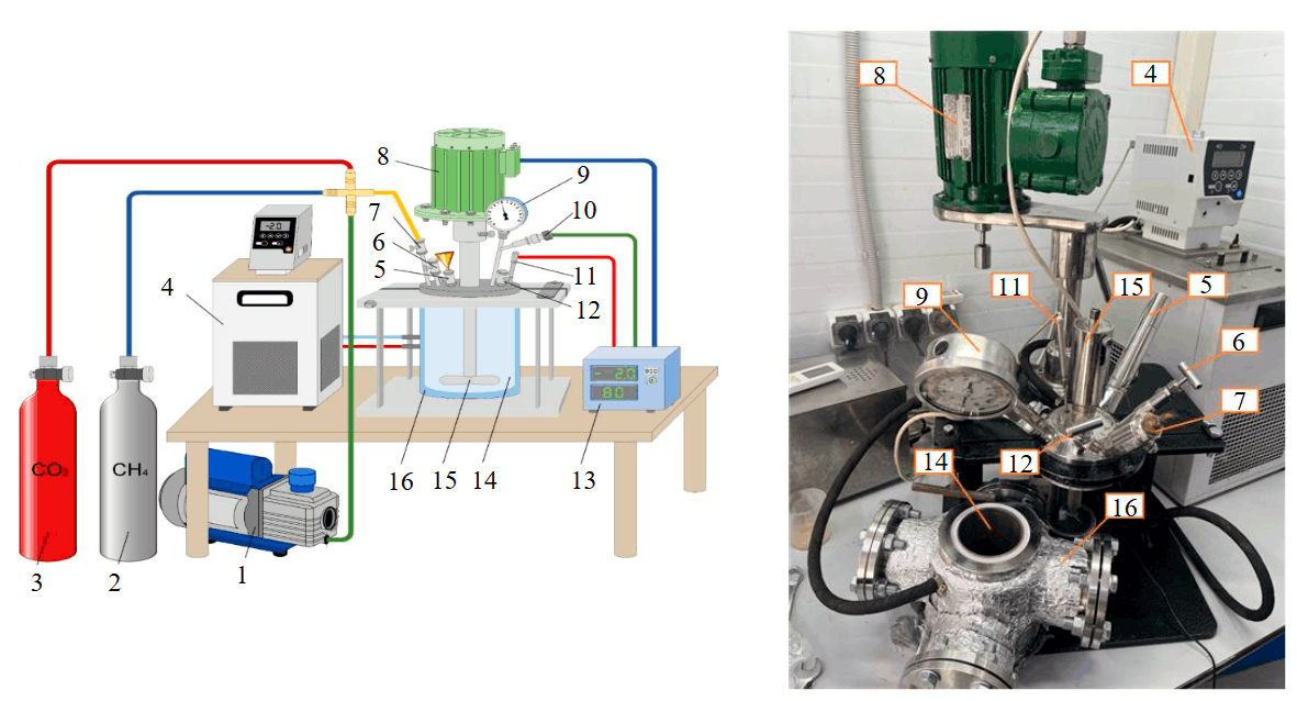
Fig.1. Schematic and photograph of the experimental setup for hydrate synthesis and dissociation
1 – vacuum pump; 2 – CH4 cylinder; 3 – СО2 cylinder; 4 – thermostat; 5 – filling funnel; 6 – pressure safety valve; 7 – gas supply valve; 8 – electric motor; 9 – manometer; 10 – pressure sensor; 11 – thermocouple; 12 – pressure relief valve; 13 – control module; 14 – reactor; 15 – magnetic stirrer; 16 – water jacket
Once the methane hydrate formation was complete, the thermostat was set to –7 °С and the pressure was relieved. The resulting methane hydrate was a loose powder consisting of agglomerates no larger than 5 mm. These agglomerates were weakly bonded particles that showed no adhesion to the reactor walls or to each other. Hydrate formation continued until thermodynamic equilibrium was reached: СН4 – Teq = 0 °C, Peq = 26.4 bar; СО2 – Teq = 0 °C, Peq = 12.3 bar. The detailed procedure for СН4 and СО2 hydrate formation is described in studies [65, 66].
Once the hydrate synthesis was complete, the thermostat was set to –7 °С. When the thermos-couple 11 in the control module 13 indicated a temperature of –5 °С (actual temperature in the reactor), the pressure was relieved by opening the relief valve 12. This step promoted the self-preservation of methane hydrate and prevented its premature dissociation. The remaining methane was then evacuated from the reactor using the vacuum pump 1, and the thermostat was adjusted to –5 °С. Carbon dioxide was introduced from the cylinder 3 into the reactor 14 by opening the gas supply valve 7 until the pressure reached 30 bar. At this point, the СН4-СО2 replacement process began.
During the formation of СО2 hydrate from СН4 hydrate, three gas cap samples were collected from the reactor for compositional analysis. Temperature and pressure readings were continuously recorded by the control module 13 throughout the experiment. The replacement process was con-sidered complete when both the pressure and temperature in the reactor remained constant for 60 min. Highly porous ice was produced as a result of pressure relief and methane hydrate dissociation. Carbon dioxide was then supplied to the reactor, and СО2 hydrate was synthesized with and without the biosurfactant at –3 °C and +3 °C. The mass fraction of gas was approximately 11.04 % in the methane hydrate and 25.1 % in the carbon dioxide hydrate.
Results and discussion
The presence of surfactants accelerated hydrate growth, resulting in a 1.5-fold shorter hydrate formation time (Fig.2). Under real-life static conditions (when heat and mass transfer is not intensified by stirring), surfactants may have a far more powerful effect (at high porosity of reservoirs). Adding surfactants to water led to faster hydrate dissociation (Fig.2, d). Surfactant-driven intensification of hydrate growth and dissociation is accounted for by two factors: a reduced size of hydrate particle aggregates (the reaction area increase) and reduced surface tension of water.
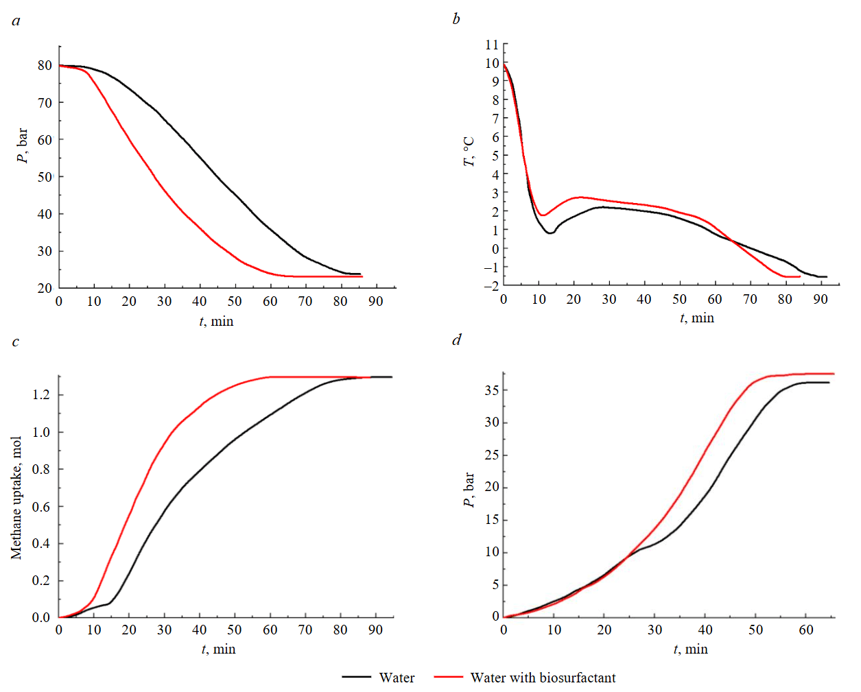
Fig.2. Pressure P (а), temperature T (b) and gas absorption (c) during formation and pressure during dissociation (d) of methane hydrate
When gas hydrate formation was over at a final temperature of –2 °С, a temperature of –3 °С was set on the thermostat, and the pressure was relieved to 0 bar (i.e., to atmospheric pressure). Dissociation started when the pressure was below equilibrium pressure. Methane hydrate dissociation was considered complete when the pressure in the reactor was constant for more than 30 min. After 30 min, the reactor lid was opened for visual inspection of the hydrate dissociation. The absence of hydrate and presence of water once again confirmed the process termination.
Self-preservation marked by an abnormally low dissociation rate is peculiar only to the thick gas hydrate sheet (with zero porosity of the layer) or for large particles [24]. Particles less than 1 mm in diameter hardly undergo self-preservation [24]. Particle aggregates should not be considered as single particles, but as a porous layer consisting of particles. The relatively high dissociation rate of methane hydrate (Fig.2, b) suggests that self-preservation can be neglected, and the size of particles in the aggregates is less than 1 mm. Natural reservoirs have areas of monolithic hydrate with large gas hydrate particles and more porous areas with numerous inclusions of sand, minerals, clay, and ice, forming a sandy silt matrix. In the dissociation of large monolithic areas (with a size of 1-10 mm and larger), it is necessary to take account of both self-preservation and porosity of the ice crust forming in the gas hydrate particle dissociation, as well as the hydrate-bearing system porosity and permeability.
For porous areas abounding with impurities, the porosity of the whole layer should be taken into account. At positive temperatures, only the reservoir porosity is considered. At negative temperatures in the reservoir, it is essential to take account of the porosity of the multiphase reservoir and the porosity of gas hydrate particles themselves, due to the formation of an ice crust on their surface. Due to slow ice melting, gas hydrate is formed from the mixture of ice with water (wet ice) saturated with carbon dioxide.
The present experimental research does not address the scale-up of the findings or extrapolate them to a real reservoir, as the necessary conditions are impossible to reproduce using the experimental setups. One of the main objectives was a comparative analysis of ways to increase the rates of methane hydrate dissociation, while reducing the pressure and forming CO2 hydrate from CH4 hydrate, when the diffusion resistance of the reservoir is insignificant. The setup and reservoir had different dimensions. In future research, it is necessary to take account of the reservoir geometry (geometric scaling) and rate of gas release from the reservoir, which depends both on the reservoir porosity and on the ratio of the transverse to longitudinal size of the reservoir (reservoir length). It is assumed in the experiment that these sizes are of the same order of magnitude, and the diffusion resistance of the porous reservoir (powder layer) is much lower than the resistance of porous ice.
The pressure drop increases the porosity of particles consisting of gas and porous ice. Ice porosity is crucial for the hydrate dissociation rate. Written in the general form, the equation for methane hydrate dissociation is related to the kinetic resistance kr and filtration (diffusion) resistance kd [25]. Without self-preservation of hydrate and at high porosity, the pressure in the pores of the particle and layer Pf becomes equal to the ambient pressure P0. Pf is related to the equilibrium hydrate pressure Peq using the parameter reflecting the effect of pore resistance(β = f(kr, kd) [25, 26]:
It was assumed that at high porosity (with pore density σp = 1010 1/m2 [25]) the condition β ≈ 0 is satisfied. Porosity is understood as the number of pores on the surface of the external ice shell of gas hydrate (1/m2). The pressure in pores becomes equal to the ambient pressure (Pf ≈ P0), and then the dissociation rate is determined only by the kinetics (kinetic resistance) and heat and mass transfer of hydrate with the environment. In this case, β → 0. The equation for methane hydrate dissociation is written as:
where Mh – the current mass of gas hydrate; M0 – the initial mass of gas hydrate; b – methane concentration; R0 – particle radius; j – hydrate dissociation rate; ρh – gas hydrate density.
The parameter β equals kd–1, while kd equals (σp)3(dp)8 [25]. At higher pore density, the condition β → 0 is satisfied. The dissociation rate is related to pore density by a cubic function. The presence of surfactant reduces the particle size R0 and increases porosity. This contributes to the dissociation rate increase according to the equation (2). This equation has a threshold asymptotic value at β → 0.
The methods of carbon dioxide hydrate formation are shown in Fig.3. According to the experimental method described, for all the curves, methane hydrate was first formed at a temperature close to 0 °С. It dissociated at a negative temperature (−3 °С). After methane hydrate dissociated and the pressure was below the equilibrium point of CO2 hydrate (5 bar), carbon dioxide was injected. It filled ice pores without forming gas hydrate (since the growth of a hydrate shell, even a porous one, would create additional diffusion resistance for the diffusion of gas into the porous ice particle). The filling of pores with carbon dioxide accelerated the diffusion during subsequent hydrate growth. Then the temperature and pressure gradually rose to the hydrate formation conditions. Due to slow ice melting, gas hydrate is probably formed from the mixture of ice with water (wet ice) saturated with carbon dioxide. During СО2 hydrate formation, the temperature in the reactor increased by 0.5-1.5 °C due to the exothermic nature of the reaction. The lowest rate of CO2 hydrate formation was recorded when no biosurfactants were used (curve 1, Fig.3). In this case, the average derivative of dP/dt is minimum. The amount of ice not converted to hydrate is maximum (20-40 % for different experiments). At t ≥ 50 min, a quasi-horizontal region of pressure has a minimum value for the three curves.
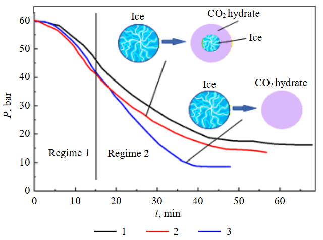
Fig.3. Changes in pressure P during CO2 hydrate formation
1 – water without surfactant, formation at –3 °C; 2 – water with surfactant, formation at –3 °C; 3 – water with surfactant, formation at +3 °C
The gas hydrate formation rate is maximum for the maximum derivative of the pressure as a function of time for the most part of the formation interval (curve 3, Fig.3) The amount of ice and CO2 converted to hydrate is also maximum for curve 3 (minimum pressure for the final plateau). The presence of surfactant (curve 2, Fig.3) leads to a decrease in diameters of ice particle aggregates and to greater defectiveness of ice than the water without surfactant exhibits (curve 1, Fig.3). Gas hydrate aggregates are smaller (with an average size of approximately 0.5-1 mm), when surfactants are added to water. The average size was determined after gas hydrate powder was taken out of the reactor after formation. Higher porosity of gas hydrate in the case of using surfactant was reported in a lot of studies involving microscope observations. Hydrate formation at a negative temperature proceeds at about the same rate as at a positive temperature (curve 3, Fig.3) only for regime 1. Approximately 30 % of ice converts to hydrate (end of regime 1). The amount of gas hydrate formed is calculated by determining how many moles of gas have been converted to hydrate, with the pressure recalculated relative to the total number of moles of gas present at the end of the hydrate formation process. Curve 3 (Fig.3) demonstrates a much faster hydrate formation rate than curve 2. It can be hypothesized that a stronger gas hydrate shell is formed in regime 2. This significantly retards the diffusion of CO2 into the ice particle (curve 2, Fig.3). Positive temperatures lead to the formation of a water film at the reaction front (phase transition boundary (Fig.4). This increases the CO2 diffusion rate and reduces the difference of thermodynamic potentials of the phase transition (in the presence of ice, water, and surfactant (curve 3, Fig.3). Due to slow ice melting, gas hydrate is formed from the mixture of ice with water (wet ice) saturated with carbon dioxide.
Without highly porous ice generation or initial methane removal, the hydrate formation rate is dozens of times lower than when the considered methods are used (Fig.3) For instance, in the study [18] the CH4-CO2 replacement along with simultaneous methane hydrate dissociation, partial methane removal, carbon dioxide injection, and CO2 hydrate formation occurred in 120 h. The amount of methane hydrate formed was 15-20 times lower than that obtained using the formation methods described in this study. A significant increase in the sample mass results in a proportional increase in the total time needed for CH4-CO2 exchange. Direct replacement of CH4 with CO2 produces mixed hydrate of methane and carbon dioxide. Some of methane molecules are occupied by hydrate cells. This impairs the efficiency of this technology. These negative effects can be mitigated by adaptive management of heat and mass transfer processes in the hydrate reservoir.
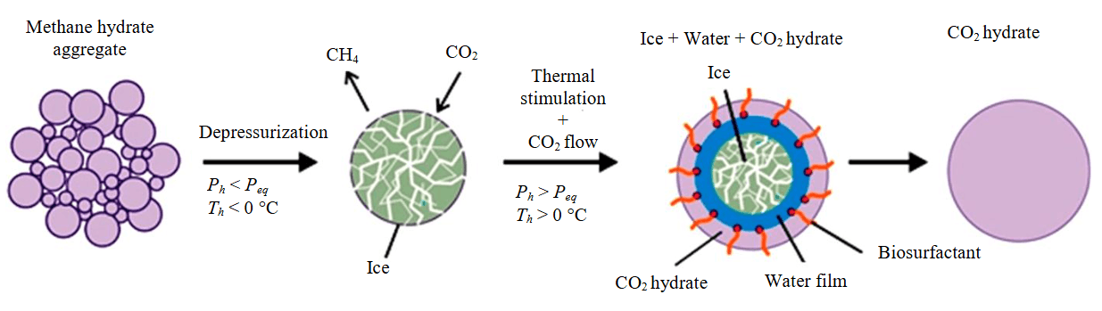
Fig.4. Diagram of СН4-СО2 replacement during formation of highly porous fine-grained ice
Ph – hydrate pressure; Peq – equilibrium hydrate pressure; Th – hydrate temperature
Gas hydrate formation in highly porous ice can be analyzed by analogy with methane hydrate dissociation using the equation (2). High porosity (β ≈ 0) means that there is no diffusion resistance. The formation rate is determined by the kinetics of growth, diameter of particles (their specific surface area), and heat and mass transfer. High formation rates confirm the weak role of diffusion. The СН4-СО2 replacement proceeding with methane in the reservoir results in the formation of mixed hydrate (СН4-СО2). Methane production can be increased by implementing a combination of different techniques. During drilling, conditions for artificial depressurization of the hydrate reservoir are created, resulting in reduced pressure and CH4 hydrate degradation. The methane released can be extracted. The heating of the reservoir by circulating the heat transfer fluid increases the temperature, which reduces the hydrate stability and accelerates methane release. Biosurfactants promote the hydrate structure destruction, accelerating the release of methane from the reservoir. Methane release is broken down into three stages: initial drilling of the reservoir and its depressurization allowing for gradual hydrate destruction; thermal exposure increasing the temperature and creating favorable conditions for hydrate destruction; adding biosurfactant facilitating methane release and minimizing the risk of hydrate re-formation. Thus, methane is completely removed by successively using the specified methods, providing maximum gas extraction before carbon dioxide injection for subsequent replacement. Coupling depressurization and thermal stimulation in the gas hydrate reservoir (curve 3, Fig.3) allows for ice melting and water film formation. This enhances the effect of surfactants and promotes the kinetics. The СН4-СО2 replacement during the formation of highly porous fine-grained ice is schematically shown in Fig.4.
Surfactant present in the water film enhances the hydrate growth kinetics. Adding surfactants reduces the excess surface energy and the difference of thermodynamic potentials Δµduring the phase transition from gas and liquid to CO2 hydrate. Thus, high rates of СН4-СО2 replacement are ensured by the following factors: decreased sizes of particles and aggregates, high porosity of ice particles and layer of particles, and reduced difference of thermodynamic potentials.
The obtained research findings can be used for developing the technologies of natural gas production from hydrate-bearing reservoirs using the depressurization method, supplying biosurfactants and injecting СО2. Once a hydrate-bearing reservoir is drilled and depressurized, methane is released from it. As a result, the hydrate reservoir becomes more porous. This is crucial, as the gas hydrate reservoir initially exhibits low permeability, which prevents the penetration of biosurfactant into it. After drilling and depressurization, biosurfactant is injected into the hydrate-bearing reservoir. This breaks the crystal lattice, which also facilitates methane release. Then carbon dioxide is injected into the reservoir, and natural gas is evacuated at the same time. This process is feasible, as with biosurfactants carbon dioxide hydrate is more likely to form than methane hydrate. A separator is installed at the well outlet to separate СО2 in the extracted methane. The gas produced passes through water in the separator, resulting in the dissolution of СО2 in the water and the formation of purified methane at the outlet. The mathematical equations derived will make it possible to predict methane hydrate dissociation time, which would remove the uncertainty associated with carbon dioxide injection into the reservoir.
Conclusion
Biosurfactants accelerate both the growth and dissociation of methane hydrates. The enhanced growth rate in the presence of biosurfactants is primarily attributed to the reduced size of hydrate particle aggregates and lower water surface tension. The increased dissociation rate results from the higher porosity of ice achieved by reducing the reactor pressure. Biosurfactants also promote faster CO2 hydrate formation. The high СН4-СО2 replacement rate is achieved through the following key factors: reduction in the size of particles and aggregates, attainment of high porosity in both particles and the ice layer, and favorable thermodynamic conditions resulting from decreased water surface tension.
The proposed sequential phase transition method is expected to reduce the total time required for CO2 hydrate synthesis by two to three orders of magnitude compared to direct СН4-СО2 replacement. Furthermore, methane replacement with carbon dioxide in highly porous ice effectively prevents the formation of mixed (methane-carbon dioxide) hydrates.
References
- Jinlong Cui, Zhenfeng Sun, Xiaohui Wang et al. Fundamental mechanisms and phenomena of clathrate hydrate nucleation. Chinese Journal of Chemical Engineering. 2019. Vol. 27. Iss. 9, p. 2014-2025. DOI: 10.1016/j.cjche.2018.12.016
- Nakane R., Shimosato Y., Gima E. et al. Phase equilibrium condition measurements in carbon dioxide hydrate forming system coexisting with seawater. The Journal of Chemical Thermodynamics. 2021. Vol. 152. N 106276. DOI: 10.1016/j.jct.2020.106276
- Minshull T.A., Marín-Moreno H., Betlem P. et al. Hydrate occurrence in Europe: A review of available evidence. Marine and Petroleum Geology. 2020. Vol. 111, p. 735-764. DOI: 10.1016/j.marpetgeo.2019.08.014
- Yan Xie, Rui Li, Xiao-Hui Wang et al. Review on the accumulation behavior of natural gas hydrates in porous sediments. Journal of Natural Gas Science and Engineering. 2020. Vol. 83. N 103520. DOI: 10.1016/j.jngse.2020.103520
- Gambelli A.M. Methane replacement into hydrate reservoirs with carbon dioxide: Main limiting factors and influence of the gaseous phase composition, over hydrates, on the process. Chemical Engineering Journal. 2023. Vol. 478. N 147247. DOI: 10.1016/j.cej.2023.147247
- Na Wei, Jun Pei, Haitao Li et al. Classification of natural gas hydrate resources: Review, application and prospect. Gas Science and Engineering. 2024. Vol. 124. N 205269. DOI: 10.1016/j.jgsce.2024.205269
- Wenfeng Ruan, Cong Hu, Zhenghui Li, Yonggang Jia. Effects of the Last Deglaciation climate warming on hydrate dissociation in the northern South China Sea. Journal of Marine Systems. 2024. Vol. 242. N 103945. DOI: 10.1016/j.jmarsys.2023.103945
- Sinehbaghizadeh S., Saptoro A., Mohammadi A.H. CO2 hydrate properties and applications: A state of the art. Progress in Energy and Combustion Science. 2022. Vol. 93. N 101026. DOI: 10.1016/j.pecs.2022.101026
- Yamamoto K., Nagakubo S. Review of Energy Efficiency of the Gas Production Technologies From Gas Hydrate-Bearing Sediments. Frontiers in Energy Research. 2021. Vol. 9. N 741715. DOI: 10.3389/fenrg.2021.741715
- Chuvilin E.M., Bukhanov B.A., Grebenkin S.I., Zhmaev M.V. Effect of gas hydrates on physical properties of permafrost. Georesursy. 2025. Vol. 27. N 3, p. 101-110 (in Russian). DOI: 10.18599/grs.2025.3.8
- Jinjie Wang, Hon Chung Lau. Thickness of gas hydrate stability zone in permafrost and marine gas hydrate deposits: Analysis and implications. Fuel. 2020. Vol. 282. N 118784. DOI: 10.1016/j.fuel.2020.118784
- Dallimore S.R., Collett T.S. Summary and implications of the Mallik 2002 Gas Hydrate Production Research Well Program. Scientific Results from the Mallik 2002 Gas Hydrate Production Research Well Program, Mackenzie Delta, Northwest Territories, Canada. Natural Resources Canada, 2005. Geological Survey of Canada, Bulletin 585, p. 36. DOI: 10.4095/220714
- Bing Li, Youhong Sun, Wei Guo et al. The mechanism and verification analysis of permafrost-associated gas hydrate formation in the Qilian Mountain, Northwest China. Marine and Petroleum Geology. 2017. Vol. 86, p. 787-797. DOI: 10.1016/j.marpetgeo.2017.05.036
- Collett T.S., Lee M.W., Agena W.F. et al. Permafrost-associated natural gas hydrate occurrences on the Alaska North Slope. Marine and Petroleum Geology. 2011. Vol. 28. Iss. 2, p. 279-294. DOI: 10.1016/j.marpetgeo.2009.12.001
- Yakushev V.S., Chuvilin E.M. Natural gas and gas hydrate accumulations within permafrost in Russia. Cold Regions Science and Technology. 2000. Vol. 31. Iss. 3, p. 189-197. DOI: 10.1016/S0165-232X(00)00012-4
- Gavrilov A., Malakhova V., Pizhankova E., Popova A. Permafrost and Gas Hydrate Stability Zone of the Glacial Part of the East-Siberian Shelf. Geosciences. 2020. Vol. 10. Iss. 12. N 484. DOI: 10.3390/geosciences10120484
- Tian Wang, Lunxiang Zhang, Lingjie Sun et al. Methane recovery and carbon dioxide storage from gas hydrates in fine marine sediments by using CH4/CO2 replacement. Chemical Engineering Journal. 2021. Vol. 425. N 131562. DOI: 10.1016/j.cej.2021.131562
- Xuemin Zhang, Shanling Zhang, Shaoqi Yin et al. Research progress of the kinetics on natural gas hydrate replacement by CO2-containing mixed gas: A review. Journal of Natural Gas Science and Engineering. 2022. Vol. 108. N 104837. DOI: 10.1016/j.jngse.2022.104837
- Kim Y.-G., Kim S., Lee D.-H. et al. Occurrence of active gas hydrate mounds in the southwestern slope of the Chukchi Plateau, Arctic Ocean. Episodes. 2020. Vol. 43. N 2, p. 811-823. DOI: 10.18814/epiiugs/2020/020053
- Shakhova N., Semiletov I., Chuvilin E. Understanding the Permafrost–Hydrate System and Associated Methane Releases in the East Siberian Arctic Shelf. Geosciences. 2019. Vol. 9. Iss. 6. N 251. DOI: 10.3390/geosciences9060251
- Chang Chen, Yu Zhang, Xiaosen Li et al. Experimental investigation into gas production from methane hydrate in sediments with different contents of illite clay by depressurization. Energy. 2024. Vol. 296. N 131181. DOI: 10.1016/j.energy.2024.131181
- Lei Yang, Yulong Liu, Hanquan Zhang et al. The status of exploitation techniques of natural gas hydrate. Chinese Journal of Chemical Engineering. 2019. Vol. 27. Iss. 9, p. 2133-2147. DOI: 10.1016/j.cjche.2019.02.028
- Jing-Chun Feng, Bo Li, Xiao-Sen Li, Yi Wang. Effects of depressurizing rate on methane hydrate dissociation within large-scale experimental simulator. Applied Energy. 2021. Vol. 304. N 117750. DOI: 10.1016/j.apenergy.2021.117750
- Dong Mo, Weiping Shi. Analytical model on natural gas hydrate dissociation with different phase equilibrium curves. International Journal of Heat and Mass Transfer. 2023. Vol. 214. N 124334. DOI: 10.1016/j.ijheatmasstransfer.2023.124334
- Shihui Ma, Jia-nan Zheng, Jie Zhao, Mingjun Yang. Effects of temperature holding on methane hydrate decomposition process by thermal stimulation. The Journal of Chemical Thermodynamics. 2021. Vol. 159. N 106487. DOI: 10.1016/j.jct.2021.106487
- Liang Mu, Ramløv H., Søgaard T.M.M. et al. Inhibition of methane hydrate nucleation and growth by an antifreeze protein. Journal of Petroleum Science and Engineering. 2019. Vol. 183. N 106388. DOI: 10.1016/j.petrol.2019.106388
- Tupsakhare S.S., Castaldi M.J. Efficiency enhancements in methane recovery from natural gas hydrates using injection of CO2/N2 gas mixture simulating in-situ combustion. Applied Energy. 2019. Vol. 236, p. 825-836. DOI: 10.1016/j.apenergy.2018.12.023
- Wonjung Choi, Junghoon Mok, Jonghyuk Lee et al. Effective CH4 production and novel CO2 storage through depressurization-assisted replacement in natural gas hydrate-bearing sediment. Applied Energy. 2022. Vol. 326. N 119971. DOI: 10.1016/j.apenergy.2022.119971
- Pengfei Wang, Ying Teng, Yusheng Zhao, Jinlong Zhu. Experimental Studies on Gas Hydrate-Based CO2 Storage: State-of-the-Art and Future Research Directions. Energy Technology. 2021. Vol. 9. Iss. 7. N 2100004. DOI: 10.1002/ente.202100004
- Misyura S., Strizhak P., Meleshkin A. et al. A Review of Gas Capture and Liquid Separation Technologies by CO2 Gas Hydrate. Energies. 2023. Vol. 16. Iss. 8. N 3318. DOI: 10.3390/en16083318
- Weiguo Liu, Qianqian Li, Yongchen Song et al. Diffusion Theory of Formation of Gas Hydrate from Ice Powder without Melting. Energy Procedia. 2014. Vol. 61, p. 513-522. DOI: 10.1016/j.egypro.2014.11.1161
- Weiguo Liu, Lijun Wang, Mingjun Yang et al. Experimental Study on the Methane Hydrate Formation from Ice Powders. Energy Procedia. 2014. Vol. 61, p. 619-623. DOI: 10.1016/j.egypro.2014.11.1184
- Peng Xiao, Juan-Juan Li, Wan Chen et al. Enhanced formation of methane hydrate from active ice with high gas uptake. Nature Communications. 2023. Vol. 14. N 8068. DOI: 10.1038/s41467-023-43487-6
- Kreven D.V., Vlasov V.A. Diffusion model of gas hydrate formation from ice considering the gas pressure drop. Results in Engineering. 2023. Vol. 20. N 101396. DOI: 10.1016/j.rineng.2023.101396
- Falenty A., Salamatin A.N., Kuhs W.F. Kinetics of CO2-Hydrate Formation from Ice Powders: Data Summary and Modeling Extended to Low Temperatures. The Journal of Physical Chemistry C. 2013. Vol. 117. Iss. 16, p. 8443-8457. DOI: 10.1021/jp310972b
- Farhadian A., Heydari A., Maddah M. et al. Renewable biosurfactants for energy-efficient storage of methane: An experimental and computational investigation. Chemical Engineering Journal. 2022. Vol. 427. N 131723. DOI: 10.1016/j.cej.2021.131723
- Palodkar A.V., Jana A.K. Clathrate hydrate dynamics with synthetic- and bio-surfactant in porous media: Model formulation and validation. Chemical Engineering Science. 2020. Vol. 213. N 115386. DOI: 10.1016/j.ces.2019.115386
- Bavoh C.B., Broni-Bediako E., Marfo S.A. Review of Biosurfactants Gas Hydrate Promoters. Methane. 2023. Vol. 2. Iss. 3, p. 304-318. DOI: 10.3390/methane2030020
- Lanoil B.D., Sassen R., La Duc M.T. et al. Bacteria and Archaea Physically Associated with Gulf of Mexico Gas Hydrates. Applied and Environmental Microbiology. 2001. Vol. 67. Iss. 11. p. 5143-5153. DOI: 10.1128/AEM.67.11.5143-5153.2001
- Arora A., Cameotra S.S., Kumar R. et al. Effects of biosurfactants on gas hydrates. Journal of Petroleum & Environmental Biotechnology. 2014. Vol. 5. Iss. 2. N 170. DOI: 10.4172/2157-7463.1000170
- Kubicki S., Bollinger A., Katzke N. et al. Marine Biosurfactants: Biosynthesis, Structural Diversity and Biotechnological Applications. Marine Drugs. 2019. Vol. 17. Iss. 7. N 48. DOI: 10.3390/md17070408
- Rogers R.E., Kothapalli C., Lee M.S., Woolsey J.R. Catalysis of Gas Hydrates by Biosurfactants in Seawater-Saturated Sand/Clay. The Canadian Journal of Chemical Engineering. 2003. Vol. 81. Iss. 5, p. 973-980. DOI: 10.1002/cjce.5450810508
- Guochang Zhang, Rogers R.E., French W.T., Wenjian Lao. Investigation of microbial influences on seafloor gas-hydrate formations. Marine Chemistry. 2007. Vol. 103. Iss. 3-4, p. 359-369. DOI: 10.1016/j.marchem.2006.10.005
- Arora A., Cameotra S.S., Kumar R. et al. Biosurfactant as a Promoter of Methane Hydrate Formation: Thermodynamic and Kinetic Studies. Scientific Reports. 2016. Vol. 6. N 20893. DOI: 10.1038/srep20893
- Strukov D.A., Kartopolcev S.A., Sagidullin A.K. et al. Study of the kinetics of methane-carbon dioxide exchange in gas hydrates below the ice melting point. Experimental data and computational model. Thermochimica Acta. 2024. Vol. 736. Iss. 179737. DOI: 10.1016/j.tca.2024.179737
- Wen-Na Wei, Bo Li, Quan Gan, Yuan-Le Li. Research progress of natural gas hydrate exploitation with CO2 replacement: A review. Fuel. 2022. Vol. 312. N 122873. DOI: 10.1016/j.fuel.2021.122873
- Yanhong Wang, Xuemei Lang, Shuanshi Fan et al. Review on Enhanced Technology of Natural Gas Hydrate Recovery by Carbon Dioxide Replacement. Energy & Fuels. 2021. Vol. 35. Iss. 5, p. 3659-3674. DOI: 10.1021/acs.energyfuels.0c04138
- Musakaev N.G., Khasanov M.K., Borodin S.L. The mathematical model of the gas hydrate deposit development in permafrost. International Journal of Heat and Mass Transfer. 2018. Vol. 118, p. 455-461. DOI: 10.1016/j.ijheatmasstransfer.2017.10.127
- Schipachev A.M., Dmitrieva A.S. Application of the resonant energy separation effect at natural gas reduction points in order to improve the energy efficiency of the gas distribution system. Journal of Mining Institute. 2021. Vol. 248, p. 253-259. DOI: 10.31897/PMI.2021.2.9
- Gajanayake S.M., Gamage R.P., Xiao-Sen Li, Huppert H. Natural gas hydrates – Insights into a paradigm-shifting energy resource. Energy Reviews. 2023. Vol. 2. Iss. 1. N 100013. DOI: 10.1016/j.enrev.2022.100013
- Mingjun Yang, Jie Zhao, Jia-nan Zheng, Yongchen Song. Hydrate reformation characteristics in natural gas hydrate dissociation process: A review. Applied Energy. 2019. Vol. 256. N 113878. DOI: 10.1016/j.apenergy.2019.113878
- Goel N. In situ methane hydrate dissociation with carbon dioxide sequestration: Current knowledge and issues. Journal of Petroleum Science and Engineering. 2006. Vol. 51. Iss. 3-4, p. 169-184. DOI: 10.1016/j.petrol.2006.01.005
- Sadeh E., Farhadian A., Mohammadi A. et al. Energy-efficient storage of methane and carbon dioxide capture in the form of clathrate hydrates using a novel non-foaming surfactant: An experimental and computational investigation. Energy Conversion and Management. 2023. Vol. 293. N 117475. DOI: 10.1016/j.enconman.2023.117475
- Gautam, Sahoo S. Experimental investigation on different activated carbons as adsorbents for CO2 capture. Thermal Science and Engineering Progress. 2022. Vol. 33. N 101339. DOI: 10.1016/j.tsep.2022.101339
- Yi Lu, Hui Wang, Qingping Li et al. CO2 storage behavior via forming hydrate from N2/CO2 gas mixtures in the presence of initial SI CO2 hydrate seeds. Chemical Engineering Journal. 2022. Vol. 450. Part 2. N 138001. DOI: 10.1016/j.cej.2022.138001
- Bhattacharjee G., Kumar A., Sakpal T., Kumar R. Carbon Dioxide Sequestration: Influence of Porous Media on Hydrate Formation Kinetics. ACS Sustainable Chemistry & Engineering. 2015. Vol. 3. Iss. 6, p. 1205-1214. DOI: 10.1021/acssuschemeng.5b00171
- Du Wang, Xin Ren, Jinkun Zhang et al. Comparative investigation on techno-economics of cascade supercritical CO2 combined cycles for waste heat recovery of typical gas turbines. Thermal Science and Engineering Progress. 2023. Vol. 42. N 101941. DOI: 10.1016/j.tsep.2023.101941
- Yao Liu, Biyu Chen, Yulong Chen et al. Methane Storage in a Hydrated Form as Promoted by Leucines for Possible Application to Natural Gas Transportation and Storage. Energy Technology. 2015. Vol. 3. Iss. 8, p. 815-819. DOI: 10.1002/ente.201500048
- Lunxiang Zhang, Lei Yang, Jiaqi Wang et al. Enhanced CH4 recovery and CO2 storage via thermal stimulation in the CH4/CO2 replacement of methane hydrate. Chemical Engineering Journal. 2017. Vol. 308, p. 40-49. DOI: 10.1016/j.cej.2016.09.047
- Chun-Yu Geng, Hao Wen, Han Zhou. Molecular Simulation of the Potential of Methane Reoccupation during the Replacement of Methane Hydrate by CO2. The Journal of Physical Chemistry A. 2009. Vol. 113. Iss. 18, p. 5463-5469. DOI: 10.1021/jp811474m
- Xin Huang, Wenjiu Cai, Linsen Zhan, Hailong Lu. Study on the reaction of methane hydrate with gaseous CO2 by Raman imaging microscopy. Chemical Engineering Science. 2020. Vol. 222. N 115720. DOI: 10.1016/j.ces.2020.115720
- Azimi A., Ansarpour M., Mofarahi M. Natural gas hydrate–related disasters and case studies. Advances in Natural Gas: Formation, Processing, and Applications. Elsevier, 2024. Vol. 3: Natural Gas Hydrates, p. 191-207. DOI: 10.1016/B978-0-443-19219-7.00004-7
- Misyura S.Y., Donskoy I.G. Dissociation of gas hydrate for a single particle and for a thick layer of particles: The effect of self-preservation on the dissociation kinetics of the gas hydrate layer. Fuel. 2022. Vol. 314. N 122759. DOI: 10.1016/j.fuel.2021.122759
- Misyura S.Y., Donskoy I.G., Manakov A.Y. et al. Studying the influence of key parameters on the methane hydrate dissociation in order to improve the storage efficiency. Journal of Energy Storage. 2021. Vol. 44. Part A. N 103288. DOI: 10.1016/j.est.2021.103288
- Gaidukova O.S., Dorokhov V.V., Misyura S.Y. et al. Dissociation of methane and carbon dioxide hydrates: Synergistic effects. Fuel. 2024. Vol. 359. N 130399. DOI: 10.1016/j.fuel.2023.130399
- Nagibin P.S., Vinogrodskiy K., Shlegel N.E., Strizhak P.A. Using methane hydrate to intensify the combustion of low-rank coal fuels. Energy. 2024. Vol. 304. N 132044. DOI: 10.1016/j.energy.2024.132044