Rational design justification of the tunnel boring shield executive body for the conditions of the mines of Saint Petersburg Metrostroy

Abstract
The article discusses the features of running tunnels in difficult mining and geological conditions of the Saint Petersburg Metrostroy using modern tunnel boring shields of Herrenknecht company with hybrid executive bodies equipped with a incisors and rock cutters. The work of a hybrid executive body is analyzed when driving along a heterogeneous bottomhole massif consisting of Cambrian clay with limestone interlayers. Theoretical and experimental studies of vibroactive cones, a graphical representation of the dependence of the depth of their penetration on the axial force and axial force together with the applied shock load (the dependences of the penetration depth are interpreted as a linear dependence) have been carried out. An increase in the intensity of destruction of a heterogeneous bottomhole massif consisting of Cambrian clay and limestone interlayers using vibroactive rock-cutting tools (spiked roller) was theoretically and experimentally confirmed, while the growth of the penetration rate is determined depending on the number of their parameters. The design is considered, the principle of operation and the method of power calculation of a rotary executive body equipped with vibroactive cutters are described, on the basis of which a nomogram of the dependence of the torque and performance of the tunnel boring shield on the feed rate of the executive body to the bottom is built.
None
Introduction
For convenient and fast movement in urban conditions, underground railway transport is used – the subway. In large and modern cities, there are more than a hundred metro stations. However, in the rapidly developing and building up Saint Petersburg there are less of them – only 72, which is primarily due to the complex engineering and geological conditions of construction.
The tunneling of Saint Petersburg metro workings is carried out in complicated engineering and geological conditions at depths from 15 to 70 m [2, 8, 9]. The bottomhole massif at such depths is distinguished by a variety of rocks. As the depth of construction increases, the composition of the bottomhole massif changes from loam with the inclusion of granite pebbles and boulders to Cambrian clay with interlayers of limestones and sandstones (Fig.1) [4].
Metro construction begins with manual or mechanized boring of vertical shaft pits, followed by the construction of near-shaft yards with their inherent additional workings. Further, the construction of running tunnels, inclined passages and stations is carried out [12]. For these purposes Metrostroy uses a set of machines: SPK-6 shaft-boring machine; tunnel boring mechanized complexes KT1-5.6, KTPM-5.6 [21, 22], Herrenknecht S-782 и S-441 (for the construction of inclined passages) [7, 19] (Fig.2); pipe layers for short special pits [15, 26, 27]. Herrenknecht S-782 and S-441 are the most modern machines [16, 24].
Herrenknecht S-782 is a mechanized tunnel boring complex with active bottom-hole soil loading, designed for driving double-track tunnels with a diameter of 10.5 m in difficult mining and geological conditions [3]. Considering the complexity of the geotechnical conditions for the construction of Saint Petersburg metro, the designers of Herrenknecht preferred a hybrid rotary executive body equipped not only with incisors, but also with disk cutters [11, 13, 23].
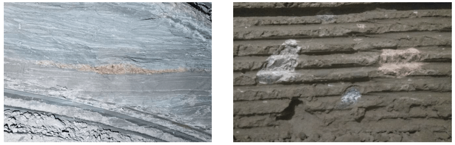
Fig.1. Limestone interlayers in clay, inclusions of granite pebbles and boulders
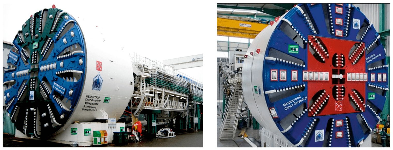
Fig.2. Tunnel-boring shields Herrenknecht S-782 and Herrenknecht S-441
During tunneling along the bottom, consisting of Cambrian clay with solid inclusions with different physical and mechanical properties [14], insufficient efficiency of the rotary executive body of the Herrenknecht S-782 tunneling shield was revealed, which consisted in the low efficiency of destruction of a heterogeneous face, an increase in torque on the executive body [5], rapid failure of rock cutting tools and low rate of penetration. Therefore, the task of creating an executive body capable of destroying both homogeneous and heterogeneous bottomhole massif without reducing the feed rate with reduced energy consumption is especially urgent. To do this, it is necessary to equip the executive body of the tunnel boring shield with vibration-shock cutters. In the future, it is necessary to perform experimental and theoretical calculations of innovations.
Methodology
To increase the intensification of the destruction of the bottomhole mass by disk roller cutters [19, 20, 25] it is proposed to impose a shock load on them, which will increase the penetration depth of the disk of cutters. Knowing the formula for determining the thickness of the cut-off chips by the rotary executive body (3), it can be concluded that an increase in the thickness of the cut-off chips will increase the feed rate of the executive body.
To theoretically determine the dependence of the depth of cutter penetration into the rock on the axial force, the formula is used
where R – disk cutter radius, mm; ƒ – rock strength; α – sharpening angle, degrees.; Рaf – axial force, kN; m – friction coefficient of the cutter metal on the rock; kb – bluntness coefficient of the disk cutter.
To determine the dependence of the depth of penetration of the cutter into the rock on the applied shock load, the formula is used
where z – blades number; d – disk cutter radius, m; σcs – compressive strength of rock, Pa; Рim – impact power, W; nim – impact frequency, s–1.
To determine the dependence of the penetration depth on the axial force with an imposed shock load, let us turn to the additivity rule.
In the course of the calculations, it was revealed that when a shock load was applied to the disk roller cutters, the increase in the value of the depth of penetration of the cutter disk into the Cambrian clay was 27 %, and 40 % into the limestone. Further, this must be verified experimentally: a stand was designed and manufactured for research (Fig.3).
The experimental stand consists of a frame 1 and a movable frame 6, on which a perforator 8 with a bar 5, a roller cutter model 4 and a centering guide 3 is fixed by means of a clamp 7. Next, the movable frame is installed in frame 1 above the rock sample 2. From above, on the movable frame for the purpose of changing the axial force Paf, replaceable bagged weights were installed.
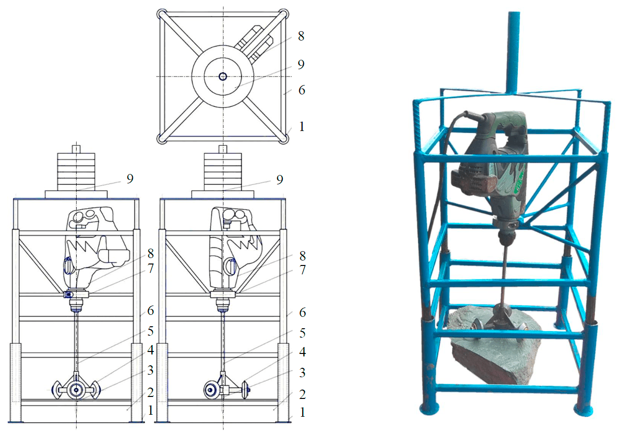
Fig.3. Experemental stand
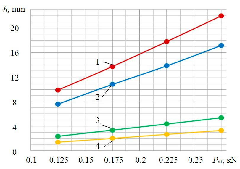
Fig.4. Dependences of the depth of penetration of the disk of cutters into samples of Cambrian clay and limestone on the axial force
and axial force together with the imposition of a shock load 1 – Cambrian clay (Рaf + Аim); 2 – Cambrian clay (Рaf); 3 – limestone (Рaf + Аim); 4 – limestone (Рaf)
The studies were carried out on samples of Cambrian clay and limestone with a natural moisture content of 10 %. To achieve reliable results, the studies were carried out at 10-15 °С – the natural temperature of the destroyed bottomhole mass. Carrying out studies on rock samples with a lower moisture content (dried) would affect the reliability of the results due to increased fracturing and brittleness of the rock. Experimental studies were carried out in the allotted time interval in two operating modes of the perforator: rotational and rotational-impact. Measurement of the depth of penetration of cutter disk was made after each experiment in the series. According
to the results of experimental studies, dependencies were built (Fig.4).
After analyzing the graph, we can conclude that the increase in the penetration depth of the cutter disk into the Cambrian clay sample was 22 %, and the limestone sample – 39 %. At the same time, for a comprehensive assessment of the effect of reservoir pressure on the depth of cutter disk penetration into the rock, it is possible to further conduct experimental studies in the faces of mines.
The discrepancy between the theoretical and experimental values of the depth of penetration of the cutters is explained by the loss of impact energy due to possible deformations in the cutter model. It can be concluded that the model of destruction of samples of Cambrian clay and limestone by vibro-shock cutters describes the process under study well.
Subsequently, the design of a vibroactive cutter was developed, which was installed on the rotary executive body of the tunnel boring shield (Fig.5).
During the work on the destruction of Cambrian clay, disc roller cutters are pressed into the bottomhole mass. In the presence of solid inclusions or interlayers, the disc cutter 6 is pressed together with the pusher 3 in the guide 10 in the direction opposite to the bottom. The spring 17, centered in the annular grooves 1, compressing, allows to reduce the shock dynamics arising from changes in the physical and mechanical properties of the destroyed bottomhole mass. At the moment of compression of the spring 17, the end sensor 13 is turned on and gives a signal to turn on the oscillator 18. The generator 18 is turned on only when the cutter has been squeezed out of the plate 7. Thus, the possibility of the cutter axis hitting the front of the rotor is excluded. Vibro-shock vibrations from the oscillation generator 18 are transmitted to the roller cutter 6 through the pusher 3 and the axis 4. At this moment, the roller cutter 6 performs high-frequency and low-amplitude reciprocating movements, thereby destroying solid layers.
There are ready-made solutions for oscillators with various parameters. It is a pneumatic piston vibrator made in an aluminum casing. The principle of operation is that when air pressure is applied to the inlet, the compressed air pushes the piston, which in turn strikes the base of the housing. Optimal parameters of the oscillator: n = 2500-3000 impacts per min, Aim = 240-280 J.
The power calculation of the rotary executive body is carried out in the following sequence:
- The value of the thickness of the cut-off chips is determined, the value of which is proportional to the feed rate of the executive body to the bottom [30, 32]:
$$ h = {\mathcal{V}_\mathrm{feed}\over n_\mathrm{eb}m}, \qquad(3) $$
where vfeed – feed rate of the executive body to the bottomhole, m/s; neb – executive body rotation speed, s–1; m – the number of incisors in the cutting line (the total number of incisors installed on the rotor is 103 pieces, while 56 pieces are located with four incisors, 38 – two incisors and 9 – one incisor in the cutting line).
- Determines the cutting force on the front edge of the incisor [17]:
$$ P_{z\mathrm{c}}=P_\mathrm{cont}k_\alpha K_b(0,25+0,018th)+0,27\mathrmμ_{move} P_\mathrm{cont} F_\mathrm{av}, \qquad(4) $$
where Рcont – rock contact strength, MPa; kα – coefficient taking into account the effect of the cutting angle; kb – coefficient taking into account the effect of the width of the cutting edge of the incisor; t – spacing of incisors, mm; mmove – the coefficient of friction of the movement of the incisor on the rock; Fav – the average projection of the incisor bluntness area along the back face onto the cutting plane, mm2.
- The torque required for the destruction of the bottomhole mass with a cutting rock incisor is determined by so:
$$ \mathrm{M}_{\mathrm{p}i}=P_{z\mathrm{c}i}n_iR_{\mathrm{av}i}, \qquad(5) $$
where Pzci – force on the cutter in the group of cutters placement, kNm; ni – number of incisors in an incisor group (n1 = 9; n2 = 38; n4 = 56); Ravi – average radius of placement of groups of incisors (for a group of placement of incisors, in the cutting line of which there is one incisor – Rav1= 1.1 m; with two incisors – Rav2= 2.5 m; with four incisors – Rav4= 4.15 m).
In order to obtain the total value of the torque, it is necessary to sum up the values of the torques of the incisors groups:
$$ \mathrm {\sum M_c = M_{c1}+M_{c2} +M_{c4}}.\qquad(6) $$Similarly, the values of the cutting forces and torque are calculated, which are necessary for the destruction of the bottomhole mass with a drill bit and buckets.
- The rolling force of the disk cutters is determined [10, 29]:
$$ P_z=\frac{2,12\cdotp \root3\of{\frac{s\sigma^2_\mathrm{cs}\sigma_\mathrm{ten}}{\gamma\sqrt{RT}}RT\gamma}}{1+\psi}sin\frac{\gamma}{2},\qquad(7) $$
where s – cutting step, mm; σten – tensile strength of rock, MPa; R – cutting disk radius, mm; T – width of the cutting edge of the disc cutter, mm; γ – contact angle between tool and rock, rad.; ψ – coefficient describing the function of the distributed load (ranges from –0.2 to 0.2, decreasing as the width of the cutting-edge increases).
Experimental studies have shown that the imposition of a shock load on a rock cutting tool does not lead to a significant increase in the force on it, therefore the value of the rolling force of vibroactive cutters will correspond to the value of the rolling force of disk (Pzvibro = Pzdisc).
- Determined the torque on the rock cutting tool [1,28, 31]:
$$ \mathrm {M_{rot}}=P_2nR_\mathrm {av},\qquad(8) $$
where n – disc cutters number; Rav – average radius of cutters placement, m.
- The torque applied to the destruction of the rock by rock cutting tools is determined. To do this,
it is necessary to sum up the torques from incisors, buckets, borers, cutters:$$ \mathrm {M_{rot}=M_{inc}+M_{bucket}+M_{borer}+M+{cut}}.\qquad(9) $$ - The performance of the tunnel boring shield is determined [6]:
$$ Q\mathrm {_{theor}}=\pi R_\mathrm{shield}^2\mathcal{V}_\mathrm{feed}3600,\qquad(10) $$
where Rshield – shield radius, m.
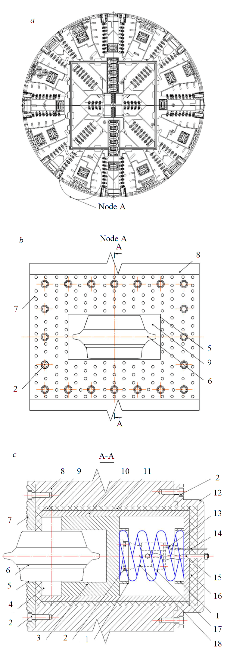
Fig.5. General view of the executive body (a), the design of the vibroactive cutter (b, c)
During the operation of the tunneling shield, the main factors limiting the rate of delivery of the executive body to the bottom are the nominal torque value and the rate of discharge of the mined rock from the bottomhole space. Thus, the executive body of the shield, armed with incisors and cutters, when driving along the bottom, consisting of clay, will have a feed rate of 0.0007 m/s (point A'), which is limited by the factors presented earlier. In this case, the value of the theoretical productivity will be 5388 m3/day (point A''), which corresponds to a penetration rate of 21.4 m/day.
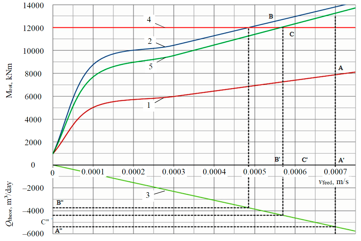
Fig.6. Nomogram of the dependence of the torque and productivity on the feed rate of the executive body 1 – Cambrian clay; 2 – Cambrian clay with a layer of limestone; 3 – productivity; 4 – Mnom; 5 – Cambrian clay with a layer of limestone (destruction by vibroactive cutters and an improved cutting pat-tern)
When the head of the tunneling shield operates on the combined bottom, consisting of clay with limestone interlayers up to 1 m thick, the feed rate will be equal to 0.000485 m/s (point B') and is limited by the nominal torque (point B), which is with 12000 kNm. This is due to the increased values of the forces on the cutters and, as a consequence, the growth of the torque associated with a change in the physical and mechanical properties of the mass being destroyed. At such a feed rate, the value of the theoretical productivity will be 3733 m3/day (point B"), or 16.4 m/day – the rate of penetration.
Having improved the executive body by installing vibroactive cutters, the thickness of the cut-off chips, as well as the feed rate of the cutting head to the bottom, will increase by 1.3 times. In this case, the value of the feed rate will be limited by the nominal torque (point C) and will be 0.00057 m/s (point C') with a theoretical productivity of 4387 m3/day (point C"), or the penetration rate of 19.7 m/day.
Conclusion
To optimize the process of destruction of the mixed bottomhole massif in the mining and geological conditions of the mines of Metrostroy in Saint Petersburg, a patented design of a rotary executive body of a tunnel boring shield equipped with vibroactive cutters has been proposed.
In the course of theoretical and experimental studies, a linear dependence of the increase in the value of the penetration depth of disk cutters into rock samples was revealed when an impact load was applied to them, and for the Cambrian clay the increase was 22 %, for limestone – 39 %.
The power calculation of the rotary executive body and the productivity of the tunnel-boring shield showed an increase in the rate of tunneling with a non-uniform bottomhole mass, consisting of Cambrian clay and limestone interlayers in the mining and geological conditions of the mines of Saint Petersburg Metrostroy by 30 % when installing the developed vibroactive cutters.
In addition to increasing the rate of penetration, the installation of vibroactive cutters will significantly reduce the wear of rock cutting tools. Therefore, in future, it is necessary to investigate and conduct production tests of the reliability and maintainability of the developed design.
- References
- Averin E.A. Foreign experience in using wedge disk rolling cutters for equipping tunneling shields. Gornye nauki i tekhnologii. 2018. N. 4, p. 41-50. DOI: 10.17073/2500-0632-2018-4-41-50 (in Russian).
- Aleksandrova O.Yu. Problems of the development of the underground space of St. Petersburg and geological processes. Journal of Mining Institute. 2008. Vol. 176, p. 209-212 (in Russian).
- Budnikov V.B. Mathematical description of tunnel shield complex dynamics. Izvestiya Tulskogo gosudarstvennogo universiteta. Tekhnicheskie nauki. 2012. Vol. 11. Part 1, p. 194-198 (in Russian).
- Verbilo P.E., Kabanov E.I. Risk assesment during project development of flooded tunnels plugging. Gornyi informatsionno-analiticheskii byulleten.2017. N S5-2, p. 25-33 (in Russian).
- Borisov A. Yu., Khoreshok A.A., Mametyev L.E., Tsekhin A.M. The influence of the shape of the housing of the working body mining combine on the loading disk tool. Gornoe oborudovanie i elektromekhanika. 2016. N 6 (124), p. 30-37 (in Russian).
- Polyakov A.V., Zhabin A.B., Chebotarev P.N., Khachaturian W.H. Selection and calculation of cutting head for earth pressure balance tunnel boring machines. Izvestiya Tulskogo gosudarstvennogo universiteta. Nauki o Zemle. 2019. Iss. 4, p. 139-149 (in Russian).
- Giginyak I.E. Construction of an inclined course of a metro station with the help of the TPMK of the “Herrenknecht” company in St. Petersburg. Metro i tonneli. 2009. N 5, р. 4-5 (in Russian).
- Dashko R.E., Kotyukov P.V., Shidlovskaya A.V. Hydrogeological conditions effect on safety of underground space expansion during transport tunnel construction. Journal of Mining Institute. 2012. Vol. 199, p. 9-16 (in Russian).
- Dashko R.E., Kotyukov P.V. The engineering geological control of underground transport tunnels exploitation reliability in Saint Petersburg. Journal of Mining Institute. 2011. Vol. 190, p. 71-77.
- Zhabin A.B., Polyakov A.V., Averin E.A. Comparison of methods to calculate forces on frontal disc cutters in rock breaking process in Russia and abroad. Gornyi zhurnal. 2018. N 12, p. 65-68. DOI: 10.17580/gzh.2018.12.13 (in Russian).
- Zadkov D.A., Gabov V.V., Nguyen K.L. Features of elementary burst formation during cutting coals and isotropic materials with reference cutting tool of mining machines. Journal of Mining Institute. 2019. Vol. 236, p. 153-161. DOI: 10.31897/PMI.2019.2.153 (in Russian).
- Karasev E.A. Specific behaviour of prefabricated tunnel linings. Journal of Mining Institute. 2010. Vol. 185, p. 180-183 (in Russian).
- Karkashadze G.G., Babich A.V. Study of the process of rock failure of disc cutters. Gornyi informatsionno-analiticheskii byulleten . 2017.N 1, p. 109-116 (in Russian).
- Korshunov V.A., Kartashov Y.M. A new technique for the determination of ultimate strength in extention of rocks. Journal of Mining Institute. 2011. Vol. 190, p. 202-206 (in Russian).
- Lavrenko S.A., Korolev I.A. Analysis of Cambrian clay cutting during Saint-Petersburg subway construction. Gornyi zhurnal. 2018. N 2, p. 53-58. DOI: 10.17580/gzh.2018.02.08(in Russian).
- Gulelmetti V., Grasso P., Makhtaba A., Syu Sh. Mechanized tunneling in urban environments. Design and construction management methodology. St. Petersburg: Izd-vo Politekhnicheskogo universiteta, 2013, р. 602 (in Russian).
- Zhabin A.B., Polyakov A.V., Averin E.A., Linnik Yu.N. Fundamentals of the design of the executive bodies of tunnel boring machines. Gornyi informatsionno-analiticheskii byulleten. 2019. N 6, p. 156-164. DOI: 10.25018/0236-1493-2019-06-0-156-164
(in Russian). - Khoreshok A.A., Mametyev L.E., Tsekhin A.M. et al. The main stages of development and modeling parameters of the disk tool roadheaders and shearers. Gornoe oborudovanie i elektromekhanika. 2015. N 7 (116), p. 9-16 (in Russian).
- Bezrodnyi K.P., Salan A.I., Maslak V.A. et al. Settlement-free technologies in the construction of the Saint Petersburg subway. Journal of Mining Institute. 2012. Vol. 199, p. 190-195 (in Russian).
- Preis E.V., Kuznetsov V.V. Simulation of large volume elements at once or violations coal disc cutters. Gornoe oborudovanie i elektromekhanika. 2015. N 7 (116), p. 37-41 (in Russian).
- Zhabin A.B., Polyakov An.V., Polyakov Al.V. et al. Calculation of a rotory executive body for tunneling complex
KTPM-6.0. Gornoe oborudovanie i elektromekhanika. 2012. N 4, p. 26-32 (in Russian). - Lukin D.G., Yungmeister D.A., Yacheikin A.I., Isaev A.I. Improvement of shield machine KT1-5.6M cutterhead operation. Gornyi zhurnal. 2018. N 12, p. 73-77. DOI: 10.17580/gzh.2018.12.15 (in Russian).
- Zhabin A.B., Polyakov A.V., Averin E.A., Sarychev V.I. State of scientific researches in the field of rock destruction by picks at the turn of the century. Izvestiya Tulskogo gosudarstvennogo universiteta. Nauki o Zemle. 2018. N 1, p. 230-247 (in Russian).
- Gabov V.V., Nguyen Van Xuan, Zadkov D.A. et al. Scheme for the installation of cutters on screw executive bodies with cutting, coupling and group cuts. Gornyi informatsionno-analiticheskii byulleten. 2020. N S4, p. 3-14. DOI: 10.25018/0236-1493-2020-1-4-3-14 (in Russian).
- Khoreshok A.A., Kuznetsov V.V., Borisov A.Yu. Predicting the maximum volume of destroyed material with a disk tool. Gornyi informatsionno-analiticheskii byulleten. 2011. N 9, p. 299-304 (in Russian).
- Shishlyannikov D.I., Trifanov M.G., Trifanov G.D. “Ural-20R” combines loading drives evaluation in two-stage development of the face. Journal of Mining Institute. 2020. Vol. 242, p. 234-241. DOI: 10.31897/PMI.2020.2.234
- Lavrenko S., Klushnik I., Iarmolenko V. Test results for hydraulic drives of sucker-rod pumping units. ARPN Journal of Engineering and Applied Sciences. 2019. Vol. 14. N 16, p. 2881-2885.
- Li F.H., Cai Z.X., Kang Y.A. Theoretical model for estimating the wear of the disc cutter. Applied Mechanics and Materials. 2011. Vol. 90-93, p. 2232-2236. DOI: 10.4028/www.scientific.net/AMM.90-93.2232
- Rostami J. Study of pressure distribution within the crushed zone in the contact area between rock and disc cutters. International Journal of Rock Mechanics and Mining Sciences. 2013. Vol. 57, p. 172-186. DOI: 10.1016/j.ijrmms.2012.07.031
- Shishlyannikov D.I., Zvonarev I.E.Investigation of the destruction process of potash ore with a single cutter using promising cross cutting pattern. Applied Sciences. 2021. Vol. 11. Iss. 1, p. 1-11. DOI: 10.3390/app11010464
- Tumac D., Balci C. Investigations into the cutting characteristics of CCS type disc cutters and the comparison between experimental, theoretical and empirical force estimations. Tunnelling and Underground Underground Space Technology. 2015. Vol. 45, p. 84-98. DOI: 10.1016/j.tust.2014.09.009
- Zhabin А., Polyakov А., Averin Е. Scale factors for conversion of forces on disc cutters for the main domestic and foreign methods. Mining of Mineral Deposits. 2017. Vol. 11. Iss. 3, p. 50-55. DOI: 10.15407/mining11.03.050
References
- Averin E.A. Foreign experience in using wedge disk rolling cutters for equipping tunneling shields. Gornye nauki i tekhnologii. 2018. N. 4, p. 41-50. DOI: 10.17073/2500-0632-2018-4-41-50 (in Russian).
- Aleksandrova O.Yu. Problems of the development of the underground space of St. Petersburg and geological processes. Journal of Mining Institute. 2008. Vol. 176, p. 209-212 (in Russian).
- Budnikov V.B. Mathematical description of tunnel shield complex dynamics. Izvestiya Tulskogo gosudarstvennogo universiteta. Tekhnicheskie nauki. 2012. Vol. 11. Part 1, p. 194-198 (in Russian).
- Verbilo P.E., Kabanov E.I. Risk assesment during project development of flooded tunnels plugging. Gornyi informatsionno-analiticheskii byulleten. 2017. N S5-2, p. 25-33 (in Russian).
- Borisov A. Yu., Khoreshok A.A., Mametyev L.E., Tsekhin A.M. The influence of the shape of the housing of the working body mining combine on the loading disk tool. Gornoe oborudovanie i elektromekhanika. 2016. N 6 (124), p. 30-37 (in Russian).
- Polyakov A.V., Zhabin A.B., Chebotarev P.N., Khachaturian W.H. Selection and calculation of cutting head for earth pressure balance tunnel boring machines. Izvestiya Tulskogo gosudarstvennogo universiteta. Nauki o Zemle. 2019. Iss. 4, p. 139-149 (in Russian).
- Giginyak I.E. Construction of an inclined course of a metro station with the help of the TPMK of the “Herrenknecht” company in St. Petersburg. Metro i tonneli. 2009. N 5, р. 4-5 (in Russian).
- https://elibrary.ru/item.asp?id=24180224
- Dashko R.E., Kotyukov P.V., Shidlovskaya A.V. Hydrogeological conditions effect on safety of underground space expansion during transport tunnel construction. Journal of Mining Institute. 2012. Vol. 199, p. 9-16 (in Russian).
- Dashko R.E., Kotyukov P.V. The engineering geological control of underground transport tunnels exploitation reliability in Saint Petersburg. Journal of Mining Institute. 2011. Vol. 190, p. 71-77.
- Zhabin A.B., Polyakov A.V., Averin E.A. Comparison of methods to calculate forces on frontal disc cutters in rock breaking process in Russia and abroad. Gornyi zhurnal. 2018. N 12, p. 65-68. DOI: 10.17580/gzh.2018.12.13 (in Russian).
- Zadkov D.A., Gabov V.V., Nguyen K.L. Features of elementary burst formation during cutting coals and isotropic materials with reference cutting tool of mining machines. Journal of Mining Institute. 2019. Vol. 236, p. 153-161. DOI: 10.31897/PMI.2019.2.153 (in Russian).
- Karasev E.A. Specific behaviour of prefabricated tunnel linings. Journal of Mining Institute. 2010. Vol. 185, p. 180-183 (in Russian).
- Karkashadze G.G., Babich A.V. Study of the process of rock failure of disc cutters. Gornyi informatsionno-analiticheskii byulleten . 2017. N 1, p. 109-116 (in Russian).
- Korshunov V.A., Kartashov Y.M. A new technique for the determination of ultimate strength in extention of rocks. Journal of Mining Institute. 2011. Vol. 190, p. 202-206 (in Russian).
- Lavrenko S.A., Korolev I.A. Analysis of Cambrian clay cutting during Saint-Petersburg subway construction. Gornyi zhurnal. 2018. N 2, p. 53-58. DOI: 10.17580/gzh.2018.02.08 (in Russian).
- Gulelmetti V., Grasso P., Makhtaba A., Syu Sh. Mechanized tunneling in urban environments. Design and construction management methodology. St. Petersburg: Izd-vo Politekhnicheskogo universiteta, 2013, р. 602 (in Russian).
- Zhabin A.B., Polyakov A.V., Averin E.A., Linnik Yu.N. Fundamentals of the design of the executive bodies of tunnel boring machines. Gornyi informatsionno-analiticheskii byulleten. 2019. N 6, p. 156-164. DOI: 10.25018/0236-1493-2019-06-0-156-164 (in Russian).
- Khoreshok A.A., Mametyev L.E., Tsekhin A.M. et al. The main stages of development and modeling parameters of the disk tool roadheaders and shearers. Gornoe oborudovanie i elektromekhanika. 2015. N 7 (116), p. 9-16 (in Russian).
- Bezrodnyi K.P., Salan A.I., Maslak V.A. et al. Settlement-free technologies in the construction of the Saint Petersburg subway. Journal of Mining Institute. 2012. Vol. 199, p. 190-195 (in Russian).
- Preis E.V., Kuznetsov V.V. Simulation of large volume elements at once or violations coal disc cutters. Gornoe oborudovanie i elektromekhanika. 2015. N 7 (116), p. 37-41 (in Russian).
- Zhabin A.B., Polyakov An.V., Polyakov Al.V. et al. Calculation of a rotory executive body for tunneling complex KTPM-6.0. Gornoe oborudovanie i elektromekhanika. 2012. N 4, p. 26-32 (in Russian).
- Lukin D.G., Yungmeister D.A., Yacheikin A.I., Isaev A.I. Improvement of shield machine KT1-5.6M cutterhead operation. Gornyi zhurnal. 2018. N 12, p. 73-77. DOI: 10.17580/gzh.2018.12.15 (in Russian).
- Zhabin A.B., Polyakov A.V., Averin E.A., Sarychev V.I. State of scientific researches in the field of rock destruction by picks at the turn of the century. Izvestiya Tulskogo gosudarstvennogo universiteta. Nauki o Zemle. 2018. N 1, p. 230-247 (in Russian).
- Gabov V.V., Nguyen Van Xuan, Zadkov D.A. et al. Scheme for the installation of cutters on screw executive bodies with cutting, coupling and group cuts. Gornyi informatsionno-analiticheskii byulleten. 2020. N S4, p. 3-14. DOI: 10.25018/0236-1493-2020-1-4-3-14 (in Russian).
- Khoreshok A.A., Kuznetsov V.V., Borisov A.Yu. Predicting the maximum volume of destroyed material with a disk tool. Gornyi informatsionno-analiticheskii byulleten. 2011. N 9, p. 299-304 (in Russian).
- Shishlyannikov D.I., Trifanov M.G., Trifanov G.D. “Ural-20R” combines loading drives evaluation in two-stage development of the face. Journal of Mining Institute. 2020. Vol. 242, p. 234-241. DOI: 10.31897/PMI.2020.2.234
- Lavrenko S., Klushnik I., Iarmolenko V. Test results for hydraulic drives of sucker-rod pumping units. ARPN Journal of Engineering and Applied Sciences. 2019. Vol. 14. N 16, p. 2881-2885.
- Li F.H., Cai Z.X., Kang Y.A. Theoretical model for estimating the wear of the disc cutter. Applied Mechanics and Materials. 2011. Vol. 90-93, p. 2232-2236. DOI: 10.4028/www.scientific.net/AMM.90-93.2232
- Rostami J. Study of pressure distribution within the crushed zone in the contact area between rock and disc cutters. International Journal of Rock Mechanics and Mining Sciences. 2013. Vol. 57, p. 172-186. DOI: 10.1016/j.ijrmms.2012.07.031
- Shishlyannikov D.I., Zvonarev I.E. Investigation of the destruction process of potash ore with a single cutter using promising cross cutting pattern. Applied Sciences. 2021. Vol. 11. Iss. 1, p. 1-11. DOI: 10.3390/app11010464
- Tumac D., Balci C. Investigations into the cutting characteristics of CCS type disc cutters and the comparison between experimental, theoretical and empirical force estimations. Tunnelling and Underground Underground Space Technology. 2015. Vol. 45, p. 84-98. DOI: 10.1016/j.tust.2014.09.009
- Zhabin А., Polyakov А., Averin Е. Scale factors for conversion of forces on disc cutters for the main domestic and foreign methods. Mining of Mineral Deposits. 2017. Vol. 11. Iss. 3, p. 50-55. DOI: 10.15407/mining11.03.050