Energy efficiency of the linear rack drive for sucker rod pumping units
Abstract
At present, in order to increase oil production and reduce economic costs in the development of marginal fields, the development of a cluster method using compact mobile drives of sucker rod pumping units (SRPU) is relevant. The aim of the work is to analyze the ways to improve the energy efficiency of the SRPU by reducing the loss of mechanical and electrical energy, to select the most energy-efficient compact drive for the development of marginal fields in the cluster method, to carry out the kinematic and strength calculations of the drive of the selected size, to develop an adaptive control system for a group of drives in the cluster development of drillings. According to the results of the performed calculations, the linear rack-and-gear drive has the highest efficiency of the drive mechanism. The kinematic and strength calculations of a linear rack-and-gear drive with a stroke length of 1120 mm and a load of up to 8 tons are presented. It was shown that the usage of a direct torque control system and a kinetic energy storage system for the SRPU drive elements and a rod string is an effective means of reducing energy costs in oil production from marginal fields. The use of the developed system for storing and redistributing the potential energy of the rods between the SRPUs that lift oil made it possible to eliminate fluctuations in the power consumption, reduce the power peak value by three times, the peak value of the current consumed from the electric network by two times, and reduce losses in the input converter and cables by three times.
None
Introduction
The oil and gas industry has remained one of the top priorities in the economic and industrial sector of Russia for a long time [1-3]. To maintain a stable growth in the production of hydrocarbon resources, it is necessary both to develop new fields, and to improve the existing technologies and create the new ones for extracting oil as well. However, it is more difficult to maintain such growth every year, old fields are being depleted and require more and more complex and expensive equipment to support the production process, but the discovery of new fields with easily recoverable reserves is declining [4-6]. Therefore, fields with hard-to-recover reserves (TRIZ) attract much attention. According to current data, the share of hard-to-recover reserves in the total oil reserve in May 2022 exceeded 66 % [7], which indicates their high importance in the country's energy balance. TRIZ can be divided into the following groups: high-viscosity oils [8-10]; low-permeability and low-porosity reservoirs [4, 11, 12]; depleted fields [5, 13, 14]; long-distance fields [3, 15, 16]; low-productive layers [17-19]. The latter are very popular in Russia due to the presence of large oil reserves and a more convenient geographical location [20].
To increase oil production and reduce economic costs, field development is carried out in clusters [21-23]. This cluster development is not a solution to the problem due to the use of sucker rod pumping units (SRPU), in which balanced and unbalanced pumping units (S-K) are used as drives, which are of little use in the development of marginal fields [24]. Let us consider and analyze methods for improving the energy efficiency of the development of marginal fields.
Mechanical drives SRPU currently used in oil production in our days are divided into balanced and unbalanced. In balancing drives (S-K), the reciprocating movement of the suspension point of the rods is carried out by a swinging lever – a balancer connected by a crank and rod mechanism (KShM) to the transmission shaft [25]. In unbalanced drives, the reciprocating movement of the suspension point of the rods is carried out by mechanisms using flexible elements (chains or ropes) [26]. Hydraulic and linear gearless drives SRPU are also known, drives based on linear motors, linear drives based on gear-rack and lead screw-nut systems [27, 28]. It is obvious that the performance coefficient of the mechanism depends on the level of losses in the structural elements of the drive and its kinematic scheme [26, 29, 30].
The sucker rod pumping unit receives mechanical energy from the line of rods, which performs reciprocating motion by means of the pumping unit drive. It converts the electrical energy supplied to the drive motor into mechanical energy. Thus, the energy efficiency of the SRPU directly depends on the amount of electrical and mechanical energy losses in various elements of the drive construction. The main ones include losses in the SRPU drive mechanism and electrical losses in the drive motor and start-up and control equipment.
The electrical energy consumed by the drive is highly dependent on power fluctuations in the drive motor cycle. So, during the S-K operation, significant fluctuations in the power consumption occur, which can change up to seven times in one cycle of the pump. For squirrel-cage induction motors used as a drive motor, power surges lead not only to significant voltage drops in the power system, but also to thermal and mechanical overloads of the motor.
The use of reversible rack and pinion linear and chain drives leads to additional losses in the motor and in the run-up control equipment during its start-up. To reduce these losses in the drive motor control system, it is necessary to use frequency converters and energy-efficient control algorithms. In addition to frequency control of the motor, when several pump drives work together during cluster well development, it is possible to use the kinetic energy of the rod moving down when oil is lifted [27]. Thus, the energy efficiency of the SRPU drive is determined by the losses of mechanical and electrical energy during operation.
The aim of the research is to analyze ways to improve the energy efficiency of sucker rod pumping units by reducing losses of mechanical and electrical energy, to select the most energy-efficient compact drive for the development of marginal fields in a cluster method, to carry out the kinematic and strength calculations of a drive with the selected size, and to develop an adaptive control system for a group of drives in cluster well development.
Methods and materials
The research methodology includes the following steps:
- selection of a compact drive for marginal fields with the highest performance coefficient of the drive mechanism;
- kinematic calculations of the drive for the selected standard size, allowing to determine the parameters of the gear train and the maximum allowable loads and restrictions on the speed of the rack movement (number of double strokes) for the selected motor-reducer;
- strength calculations for the bending of the pinion shaft teeth, allowing to choose the material and method of heat treatment of the pinion shaft and rack and surface hardening of the teeth, withstanding a load on the rod up to 80 kN;
- determination manufacturing sequence of the parts and the drive assembly, allowing to manufacture the developed drive with a load on the rod up to 80 kN;
- development of an adaptive control system (ACS) for a group of drives on a well pad with a down stem energy recovery system that reduces the energy consumption of the actuators by controlling the number of double strokes and rod stroke.
Estimation of mechanical energy losses in drives of various designs is performed by calculating their performance coefficient.
Calculation of the SRPU drive mechanism performance coefficient
A comparison of SRPU drives was made: based on a beam-balanced pumping unit, a vertical chain drive designed by RNTC VNIIneft [25], a linear drive based on a rack-toothed wheel system developed in the present research, a drive based on a screw-nut system, and a hydraulic drive.
We use a known data for a comparative analysis of the mechanical part of the drives performance coefficient. To calculate the performance coefficient of the drive mechanism, we will consider the mechanical power of the drive motor as the input power, and the mechanical power transmitted to the polished rod as the output. The drive performance coefficient is equal to the product of its components performance coefficients.
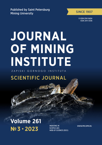
The kinematic scheme of the beam-balanced pumping unit is shown in Fig.1, a [30]. It consists of: balancer head (1); a balancer located on a pair of plain bearings (2); connecting rod-crank (3); connecting rod-crank support (4); V-belt drive (5, 6); three-stage gearbox (7), consisting of three pairs of cylindrical gears on rolling bearings (8, 10, 11); crank mechanism (9), consisting of pairs of sliding connecting rod-balancer.
The performance coefficient of the beam-balanced pumping unit is estimated by the formula
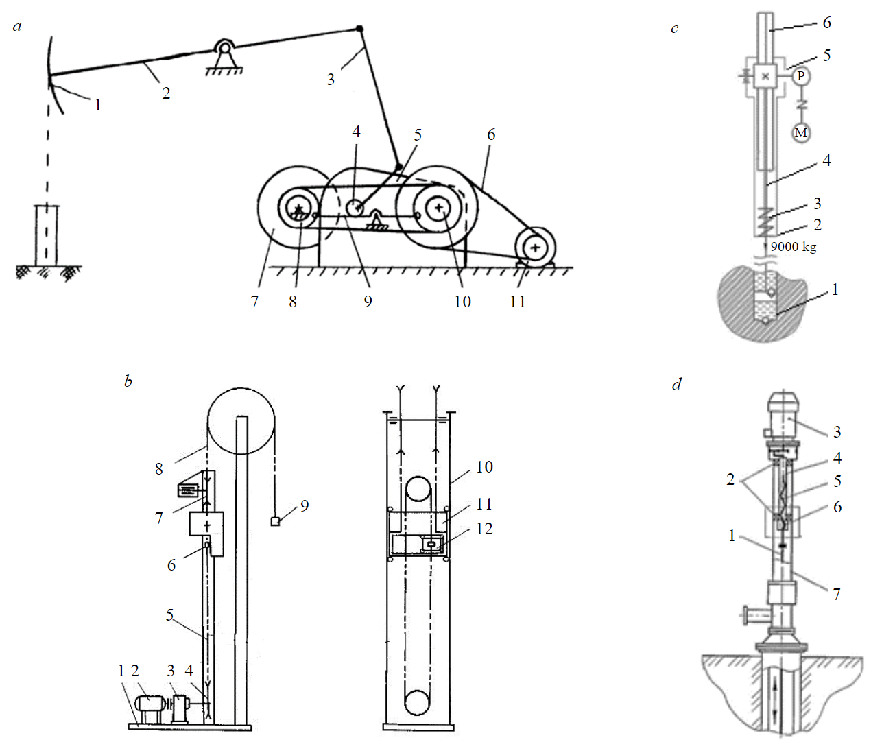
Fig.1. Kinematic scheme of a beam-balanced pumping unit (a), a drive with a movable carriage (b), a developed the linear rack-and-gear (c), a drive with a lead screw without reversing the drive motor (d)
where ηMC – performance coefficient of the mechanical coupling, ηMC = 0.98; ηVbd – performance coefficient of the V-belt drive, ηVbd = 0.96; ηRB – performance coefficient of the rolling bearing, ηRB = 0.992; ηSGD – performance coefficient of the spur gear drive, ηSGD = 0.97; k – number of gear stages, k = 3; ηCM – performance coefficient of the crank mechanism, ηCM = 0.98; ηPB – performance coefficient of the plain bearings, ηPB = 0.985. After substituting the given average values, we obtain:
that is in good agreement with the data value 0.80-0.85.
The kinematic scheme of the SRPU chain drive design [25] is shown in Fig.1, b: 1 – frame; 2 – electric motor; 3 – reducer; 4 – drive pulley; 5 – continuous flexible link (chain); 6 – attachment point; 7 – guide element; 8 – open flexible link (chain or cables); 9 – a column of rods; 10 – rack; 11 – counterweight; 12 – carriage. The drive includes a mechanical coupling, a single-stage gearbox, a chain drive, a friction pair, a guide element – a carriage, and two rolling bearings that support the drive pulley.
The formula for calculating the performance coefficient of a chain drive has the form [25]:
where ηMC – performance coefficient of the mechanical coupling, ηМC = 0.98; ηRB – performance coefficient of the rolling bearing, ηRB = 0.992; ηSGD – performance coefficient of the spur gear drive, ηSGD = 0.97; ηOSD – performance coefficient of the open chain drive, ηOSD = 0.92; ηPB – performance coefficient of the plain bearings, ηPB = 0.985.
After substituting the values, we get:
The kinematic scheme of the developed linear rack-and-gear is shown in Fig.1, c in [31]. The drive contains a KAZ-97 bevel gearbox manufactured by SEW EURODRIVE, a rack and pinion system supported by a rolling bearing, a gearbox bearing (1 – base-support; 2 – damper; 3 – housing; 4 – rack; 5 – mechanism with gearbox and electric motor; 6 – cover-guide).
The formula for calculating the performance coefficient of the linear rack-and-gear is [30]:
где ηBG – the performance coefficient the bevel gear, ηBG = 0.965; ηRB – performance coefficient of the rolling bearing, ηRB = 0.992; ηSGD – performance coefficient of the spur gear drive, ηSGD = = 0.97 [25].
After substituting the values, we get:
The design of the drive based on the lead screw-nut system without reversing the drive motor is shown in Fig.1, d [27]: 1 – rod; 2 – bearing; 3 – motor-reducer; 4 – driven shaft; 5 – lead screw; 6 – nut; 7 – support.
The formula for calculating the transmission performance coefficient of the lead screw – nut system has the form [32]:
where ηPR – performance coefficient of the planetary gearbox, ηPR = 0.96; ηRB – performance coefficient of the rolling bearing, ηRB = 0.992; ηRS – roller screw, ηRS = 0.89 [33].
After substituting the values, we get:
The performance coefficient of the SRPU hydraulic drive depends on the applied hydraulic circuit and the level of leakage. Due to the complexity of the methods used, for a comparative assessment, we use the known values ηHP = 0.91-0.75, depending on the level of leaks [34].
Based on the calculations, we choose a linear rack drive that has the highest efficiency among analogues.
Further, for the selected standard size of a linear rack-and-gear drive with a stroke length of 1120 mm and a load of up to 80 kN, a kinematic calculation was performed to determine the parameters of the gear train and the maximum allowable loads and restrictions on the rack movement speed (number of double strokes) for the selected gear motor.
Kinematic drive calculation
For calculations, the maximum stroke length of the rack (L0 = = 1120 mm), the maximum speed of the rack and the loads acting on the rod (F = 60 and 80 kN) are used. Kinematic calculation allows you to determine the linear speed of the rack, the number of double strokes per minute, select the diameter of the drive gear, the gear ratio of the gear-rack transmission, and select the gear motor.
The circumferential speed of rotation of the gear is equal to the linear speed of the rack [33]:
where D – gear wheel diameter, mm; n – wheel gear frequency, min–1.
We choose the tooth module of the gear wheel m = 8 mm. In order to reduce torque, the number of teeth is taken as low as possible Z = 14.
The gear wheel diameter is calculated by the formula [33]
The gear wheel rotation frequency is determined from the formula (1):
According to the experimental data available for SRPU, the speed of movement of the rod is from 0.25 to 0.5 m/s or from 15 to 30 m/min.
The linear speed of the rod (rack) is determined by the formula [33]
where L0 – rack stroke length; nds – number of double strokes per minute,
For the speed of the rack in the range of 0.25-0.5 m/s, we determine the number of double strokes per minute (Table 1).
Table 1
Calculated parameters of the drive with rack stroke length L0 = 1120 mm
|
V0 |
n, min–1 |
nds, min |
F,кN |
P1,kW |
|
|
m/s |
m/min |
||||
|
0.25 |
15 |
42.7 |
6.7 |
60 |
15 |
|
80 |
20 |
||||
|
0.3 |
18 |
51.2 |
8 |
60 |
18 |
|
80 |
24 |
||||
|
0.5 |
30 |
85.4 |
13.4 |
60 |
30 |
|
80 |
40 |
||||
We determine the power of the drive motor by the formula [33]
where F – acting on the rod force, N; V0 – rod stroke speed (rack), m/s.
For rack stroke speeds in the range of 0.25-0.5 m/s and rod load F = 60-80 kN, the required drive motor power is presented in Table 1. The motor power values at V0= 0.3 m/s and load F = 60 and 80 kN are 18 and 24 kW, respectively.
We determine the torque of the gear motor by the formula [33]
At the load of 60 kN, we determine the torque M = 3360 N/m.
The wheel gear rotation frequency n equals to the speed of the output shaft n2, it is calculated by the formula [33]
where n1 – motor rotation speed; i – reduction gear ratio.
Then for V0 = 0.3 m/s and F = 60-80 kN at the electric motor rotation speed n1 = 1480 min–1, the reduction gear ratio i = 28.9, which should be taken into account when choosing a geared motor.
For this drive size L0 = 1120 mm and F = 60-80 kN, a SEWEURODRIVE KAZ-97 gear motor with n1 = 1480 min–1, P1 = 22 kW, i = 18.96, n2 = 78 min–1 was selected. For this gearbox, the permissible radial load is 19.4 kN. Service factor (service factor) Sf = 1.35. Rated output torque Mn2 = 3210 N/m. Maximum output torque Mn2max = 4300 N/m. Dimensional characteristics of the reducer – hollow shaft with d = 70 mm with a key.
Thus, the use of a motor with a power of 22 kW is possible with restrictions on the speed of the rack in the range of 0.25-0.3 m/min and a maximum allowable load of 73.3 kN. A speed of 0.5 m/s at a given load of 60-80 kN is possible when using a geared motor with a power of 30 kW or more. At a speed of 0.3 m/s and a load of 80 kN, the minimum power is 24 kW, the torque is 4480 N/m. The specified parameters of the motor-gearbox do not allow working with such load.
Then, the calculations are performed for the bending strength of the gear shaft teeth, based on the results of which the material and method of heat treatment and surface hardening of the teeth are selected.
Calculation of drive elements for strength
Calculation of gear wheel teeth for bending strength is carried out according to the formula
where P – circumferential force, N; kF – load distribution ratio; yF – tooth shape factor, depending on the number of teeth, with Z = 14 yF ≈ 3.9; bw – ring gear width, bw = 139.5 mm; m – gear wheel tooth module, m = 8 mm.
The load distribution ratio is calculated by the formula [33]
where kFb – ratio of uneven load distribution along the length of the tooth, with an almost symmetrical arrangement of supports and a ratio of width bw to diameter D (ψbd = 140/112 = 1.2) kFb = 1.14 (Table 2); kFv – dynamic load factor, with 7th degree of accuracy and peripheral speed up to 3 m/s kFv = 1.15 (Table 3); kF = 1.14 ·1.15 = 1.31.
Table 2
The value of load uneven distribution ratio kFb
|
|
The location of the wheels relative to the supports |
|||
|
Symmetrical |
Asymmetrical |
Cantilevered |
||
|
More hard shaft |
Less hard shaft |
|||
|
0.2 |
1.00 |
1.00 |
1.05 |
1.15 |
|
0.4 |
1.00 |
1.04 |
1,10 |
1.22 |
|
0.6 |
1.03 |
1.08 |
1.16 |
1.32 |
|
0.8 |
1.06 |
1.13 |
1.22 |
1.45 |
|
1.0 |
1.10 |
1.18 |
1.29 |
– |
|
1.2 |
1.14 |
1.23 |
1.36 |
– |
Table3
The value of dynamic load factor kFv for spur wheels
|
Degree of accuracy |
Surface teeth hardness, НВ |
Peripheral speed v, m/s |
||
|
Up to 3 |
3-8 |
8-12 |
||
|
6 |
< 350 |
1.00 |
1.20 |
1.30 |
|
> 350 |
1.00 |
1.20 |
1.30 |
|
|
7 |
< 350 |
1.15 |
1.35 |
1.45 |
|
> 350 |
1.15 |
1.25 |
1.36 |
|
|
8 |
< 350 |
1.25 |
1.45 |
– |
|
> 350 |
1.20 |
1.35 |
|
|
|
9 |
< 350 |
1.35 |
– |
– |
|
> 350 |
1.30 |
– |
– |
|
With the base number of cycles, the permissible values of the bending strength are determined by the formula [33]
where αF0limb – stresses determined by the heat treatment mode, MPa; factor [n]Fʹ = 1.75 for steels after normalization, hardening with subsequent drawing and surface hardening, 1.8 – after bulk hardening and 1.55 – after carburizing and quenching; factor [n]Fʹʹ = 1 for stamped, 1.15 for forged and 1.3 for cast parts.
αF0limb values depends on technological parameters of the heat treatment: 1.8 НВ – normalized wheels; 500-550 MPa – bulk hardening, НRCэ = 45-55; 700 MPa – surface hardening, НRCэ = 48-58; 900 МPа – carburizing and quenching, НRCэ = 57-60.
For a stamped wheel made of hardened with subsequent drawing steel of grade 40Cr with surface hardening αF0limb = 700 MPa, for a stamped wheel made of 20Cr steel grade after carburizing αF0limb = 900 MPa. Safety factor [n]F = 1.75 for steel after surface hardening and [n]F = 1.55 for carburized steel.
We calculate the allowable stress by the formula (11):
for steel grade 40Cr after surface hardening [σ]F = 700/1.75 = 400 MPа,
for steel grade 20Cr after carburizing and quenching [σ]F = 900/1.55 = 580 MPа.
The stress in the teeth are calculated according to the formula (9):
Thus, the selected module of hardened and tempered 40Cr steel with surface hardening withstands a load of up to 80 kN.
The parts manufacturing process of the linear rack-and-gear drive with a stroke length of 1120 mm
The necessary information for the components manufacture of the SRPU linear rack-and-gear drive elements is presented in Table 4.
Тable 4
Manufacturing technology and materials for linear rack-and-gear drive parts
|
Part name |
Manufacturing type |
Workpiece/Material |
|
Rack – gear shaft (assembly) |
||
|
Gear shaft |
Milling processing |
Steel 40CrNi |
|
Rack |
Milling processing |
Steel 40Cr |
|
Small lock |
Milling processing |
Plate 20/Steel 3 |
|
Lock |
Milling processing |
Steel 45 |
|
Hob |
Turning processing |
Steel 45 |
|
Spacer |
Turning processing |
Steel 20 |
|
Liner |
Laser cutting |
Sheet 2/Steel 10 |
|
Housing (assembly) |
||
|
Bottom wall |
Milling processing |
AlMg3 |
|
Upper guiding rail |
Milling processing |
Steel 45 |
|
Side guiding rail |
Milling processing |
Steel 45 |
|
Guiding rack |
Locksmith processing |
CuZnPb 59-1 |
|
Guiding bar |
Locksmith processing |
CuZnPb 59-1 |
|
Left wall |
Milling processing |
AlMg3 |
|
Right wall |
Milling processing |
AlMg3 |
|
Upper wall |
Milling processing |
AlMg3 |
|
Ring |
Locksmith processing |
Steel 45 |
|
Substitute (welding) |
||
|
Front wall |
Laser cutting |
Plate 20/Steel10 |
|
Console |
Locksmith processing |
Plate 40/Steel 10 |
|
Console |
Locksmith processing |
Pipe 80×50×3/Steel 10 |
|
Bearings roller |
Turning processing |
Rolled bar 35/Steel 45 |
|
Corner |
Locksmith processing |
Sheet 6/Steel 10 |
|
Wall |
Laser cutting and bending |
Sheet 6/Steel 10 |
|
Lug |
Locksmith processing |
Plate 20/Steel 3 |
|
Column shaft (welding) |
||
|
Wall |
Laser and milling processing |
Plate 25/Steel 10 |
|
External compression spring |
Finished product |
|
|
Internal compression spring |
Finished product |
|
|
Pipe |
Welding |
Pipe 219×5 |
|
Plate (disk) |
Laser cutting |
Plate 25/Steel 3 |
|
Rod |
Turning processing |
Pipe 41×3.5 |
|
Valve |
Turning processing |
Rolled bar 45/Steel 3 |
|
Half cover left |
Turning processing |
CuZnPb 59-1 |
|
Half cover right |
Turning processing |
CuZnPb 59-1 |
|
Cup (welding) |
||
|
Cup disk |
Turning processing |
Plate 25/Steel 3 |
|
Cup pipe |
Turning processing |
Pipe 54×3 |
|
Casing body (welding) |
||
|
Wall |
Laser cutting and bending |
Sheet 2/ Steel 3 |
|
Handle |
Locksmith processing |
Rolled bar 14/Steel 20 |
|
Back wall |
Laser cutting |
Sheet 2/ Steel 3 |
|
Flange (welding) |
||
|
Bar |
Laser cutting |
Sheet 4/ Steel 10 |
|
Bar |
Laser cutting |
Sheet 4/ Steel 10 |
|
Bar |
Laser cutting |
Sheet 4/ Steel 10 |
Drive assembly process
(Fig.2).The lower wall of the housing was installed on the gear motor (Fig.2, a). A bearing was pressed on the gear shaft (Fig.2, b), then it was installed into the gearbox, the side wall was screwed (Fig.2, c). Then, the guiding bar with the liner was installed in the housing (Fig. 2, d).
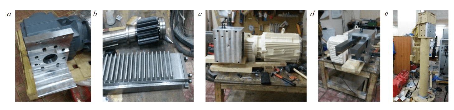
Fig.2. Stages of assembling a linear rack-and-gear drive (SRPU)
After that, the assembly of the column shaft was carried out (Fig.2, e). Springs and a cup were installed in it. Then the gearbox with the engine assembly was installed on the mounting platform, after that the holes in the column flange and the gearbox housing were combined, the substitute was installed on the gearbox housing, after that a gear rack was installed, which was turned over with the teeth down and moved along the guides until it stops, turning the shaft. The casing is installed on the substitute in a vertical position and is used in the complete set of the drive for testing on the well when protecting the mechanism from moisture and dust. When carrying out the research tests, the casing body was not installed to control visually the movements of the rack.
For the assembled drive, an adaptive control system for a group of drives on a well pad was developed with a system for recuperating the energy of the downward moving rod, which makes it possible to reduce the energy consumption of the drives by regulating the number of double strokes and the stroke of the rod.
Optimization of the oil production algorithms in terms of energy efficiency and consumption is based on mathematical modeling methods in the Simulink Power System Blockset simulation system. To create a model of the system, mathematical models of hydraulic and mechanical (system pump – rod string and SRPU drive), electrical (frequency converter, energy storage, and electric motor), electronic (regulator) components of a rod string were used [35]. The technique for developing a mathematical model of a column is presented in [36].
The adaptive ACS (automatic control system) of the drives group developed in this work generates commands for the frequency converter. The frequency converter generates a voltage of the required frequency and amplitude to the asynchronous motor power. The asynchronous electric motor connected to the gearbox through a clutch transmits torque to the rack-and-pinion mechanism, the rack is connected to the polished rod and imparts reciprocating motion to it. The kinetic energy of the downward moving rods is stored in a capacitor bank. The ACS distributes the accumulated energy between the drives when the formation fluid is lifted, provides optimal control in accordance with the well flow rate, controls the pump with optimal filling, provides programmatic hydraulic impact prevention, which improves the service life and reliability of the drive. The drives are connected to each other and to the capacitor bank by means of a DC link.
The developed adaptive scheme of the ACS, which controls the group of drives with energy recovery, and its implementation for two SRPU drives are shown in Fig.3, a. The experimental sample of the ACS has two channels for connecting two SRPU drives and is one common control and power box, which houses frequency converters (FC), a process controller and a DC link capacitor (Fig.3, b). This system also has power and information channels. The pump drives are considered as a part of the group as control objects with their own control systems, and their information channels are connected to a high-level control system through an information converter. In view of the fact that to improve the energy efficiency of oil production, the kinetic energy of the downward moving rod, accumulated in the capacitor bank, is used, the power channels of the SRPU drives are connected to each other and the energy storage device through a DC link, and one of the ACS tasks is to distribute the accumulated energy between two drives.
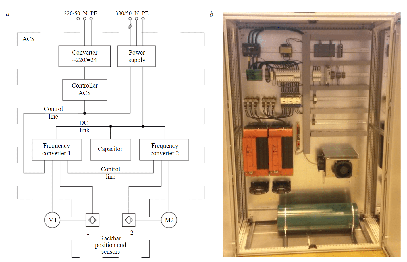
Fig.3. Functional electrical circuit of the ACS experimental sample (а); power supply and control box for the group of two SRPU drives (b)
Discussion of the results
The calculation analysis of the drives performance coefficient showed that the developed linear rack-and-gear drive has the highest efficiency among analogues. The compactness of the drive and the ability to install it directly at the wellhead can reduce operating costs and commissioning time, which also contributes to an increase in the economic efficiency of oil production.
For the drive size and for rod loads of 60-80 kN, a SEWEURODRIVE KAZ-97 was chosen the gear motor with n1 = 1480 min–1, P1 = 22 kW, i = 19, n2 = 78 min–1, Sf = 1.35, Mn2 = 3210 N/m. The use of a 22 kW motor-reducer limits the rack stroke speed within 0.25-0.3 m/min and the allowable load is 73.3 kN. With designed loads of 60-80 kN, the rack stroke speed of 0.5 m/s is acceptable for motors with power of more than 30 kW. At speed of 0.3 m/s and a load of 80 kN, the minimum power is 24 kW, and at speed of 0.5 m/s and a load of 60 kN it is 30 kW.
For the selected motor-reducer with a power of 22 kW, with the rack stroke length unchanged, restrictions on the speed of movement of the rod or loads on the rod are possible by reducing the speed of the gear and the number of double strokes, as well as the speed of the rack. This can be achieved by reducing the frequency of the current supplied to the motor, which is achieved by using a frequency converter in the drive control system. The use of the frequency converter also allows frequency converter when stopping and changing the direction of movement and reducing inertial loads when reversing the direction of movement.
At speed of 0.3 m/s, load of 80 kN, and speed of 0.5 m/s, a load of 60 kN it is required to use a gearbox with larger dimensions than SEWEURODRIVE KAZ-97. A suitable option for these conditions is the Bonfiglioli A803 24.5 P200 BN200L4 geared motor with characteristics P1 = 30 kW, n1 = 1470 min–1, n2 = 60 min–1, Mn2 = 4377 N·m, Sf = 1.5, radial load on the output shaft Rn2 = = 4330 N.
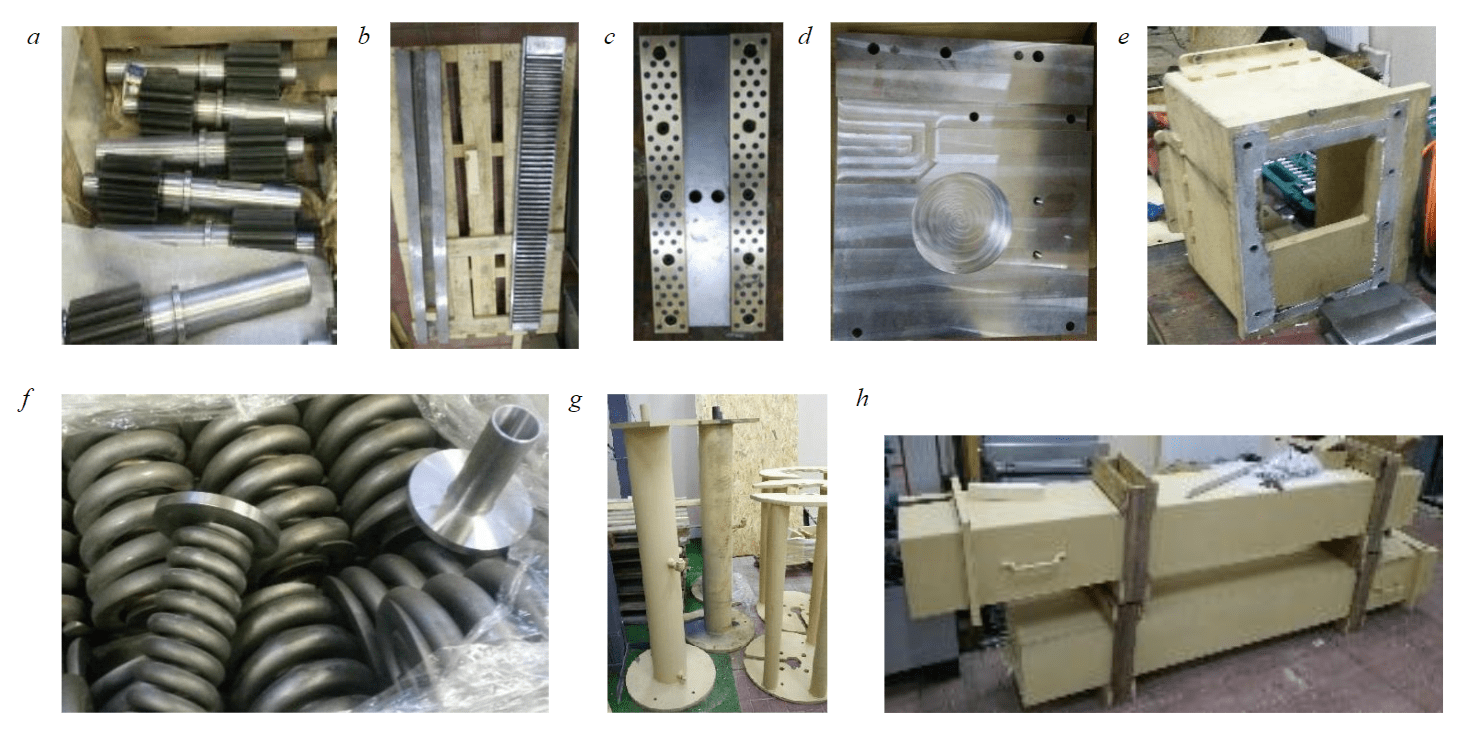
Fig.4. Assembly units of the linear rack-and-gear drive SRPU
Based on the results of the calculation for the bending strength of the teeth, a gear shaft made of tempered steel 40CrNi with surface hardening of the teeth was selected, which can withstand load up to 80 kN. Also, taking into account the calculations, materials and manufacturing technologies for the remaining components and parts of the drive were selected, and technological parameters of heat treatment were selected. Photos of some parts are shown in Fig.4: gear shaft (steel 40CrNi, tempered + the teeth surface hardened with high frequency currents (HFC) (Fig.4, a), gear rack (steel 40Cr, tempered, Fig.4, b), housing parts with liners made of brass CuZnPb 59-1 and walls made of aluminum alloy AlMg3 (Fig.4, c, d). The column shaft, casing body, substitute, and cup are welded constructions made of carbon steels.
Also, mechanical (turning and milling) processing and heat treatment (normalization) of parts (small lock, lock, hob and spacer in accordance with Table 4) for assembling a rack with the gear shaft and laser cutting of liner parts (Fig.4, c) was done. Fine machining of casing body parts (Fig.4, d) was carried out in accordance with Table 4. For the manufacture of the substitute (Table 4) the finishing machining, laser cutting, and welding of parts were performed (Fig.4, e).
Manufactured and heat-treated springs are shown in Fig.4, f. For the manufacture of the column shaft and the cup the laser cutting, turning and milling, and then welding of the parts were performed (Table 4). The column assembly with the cup and springs installed inside is shown in Fig.4, g. For the casing body manufacture the laser cutting, bending, and welding of parts were performed (Table 4), finished casings are shown in Fig.4, h.
Figure 5 shows the assembly of linear rack-and-gear drive with a stroke length of 1200 mm and a rod load of up to 80 kN, mounted on a test bench for testing at idle. The asynchronous electric motor transmitting torque to the rack-and-gear mechanism is connected through an elastic coupling to a gearbox that transmits reciprocating motion to the pump rod. The rack-and-pinion linkage consists of a toothed rack mounted on column and gear shaft that moves in the vertical direction to provide reciprocating motion of the pump rods. The toothed rim of the gear shaft during the electric motor rotation, being engaged with the toothed rack, moves it vertically upwards on the forward stroke, and vertically downwards during the reverse rotation of the motor on the reverse stroke.
The toothed rack stand at the upper end is rigidly connected to the rod column shaft by means of a cleet, which ensures the transmission of force from the drive to the rod string. In the U-shaped toothed rack stand, along the axis of the pump stroke, there is a longitudinal open channel for moving the rod inside the stand.
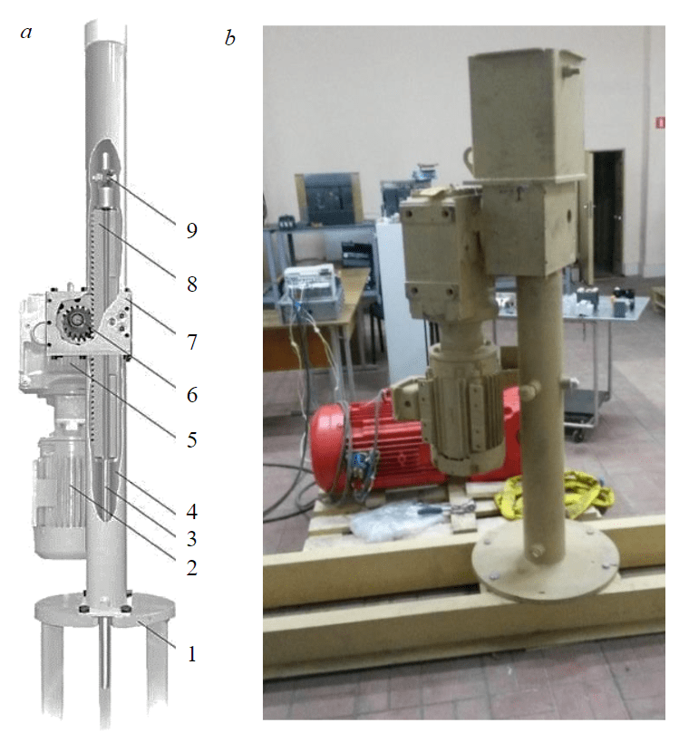
Fig.5. Design (a)and manufactured rack-and-gear drive assembly (b) 1 – basement; 2 – asynchronous electric motor; 3 – polished rod; 4 – oil bath; 5 – reducer; 6 – gear and axle; 7 – mechanism case; 8 – gear rack; 9 – rod holder
Under the bottom edge of the drive stand there is a lubrication oil pan that sinks the bottom of the stand to provide lubrication during each stroke. The lubrication pan is an annular cavity formed by two pipes hermetically connected at the bottom, filled with grease, which is pumped into the upper part of the cavity. The inner tubular wall of the pan is located around the wellhead and fits freely inside the hole of the rack to provide movement, and the outer wall of the tubular pan is located around the rack. The drive also contains a spring located inside the cavity in the pan under the lower edge of the stand for braking the rack when the pump moves down and accelerating the rack during the forward stroke of the pump up.
When the stand moves up the microprocessor control system of the linear rack-and-gear drive ensures the operation of the electric motor in the driving mode, and when it is moving down – in the braking mode (generator mode). The pump drives operating in the well cluster are connected by a DC link, to which a high-capacity capacitor bank is connected to accumulate and store the energy generated in the generator mode during the downward stroke of the rod. The accumulated energy is consumed by the electric motor in the forward stroke of the rod up during operation in the driving (loaded) mode. The microprocessor control system, which selects the pumping intensity for each pump, regulates the consumption of stored energy for lifting oil, which makes it possible to use electricity more economically.
To implement energy-efficient control of a group of drives on a cluster of closely spaced wells with energy recovery, an adaptive automatic control system is proposed that includes an input converter, a controlled current source that provides processes for charging and discharging a high-capacity capacitor (rod energy storage) and issuing commands to start and stop the drives included in the group, work in driving and generator modes. The proposed adaptive ACS makes it possible to implement algorithms for energy-efficient control of groups of SRPU drives, which reduce fluctuations in power consumption and current by choosing the plunger speed, the number of SRPU swings, and the duration of the pause between them in accordance with the flow rate of wells.
The most effective electrical way to increase performance coefficient is to use the developed system for storing and redistributing the potential energy of rods between SRPUs that lift oil. This made it possible to eliminate fluctuations in power consumption, reduce its peak value by three times, the peak value of the current consumed from the network by two times, and reduce losses in the input converter and cables by three times.
The use of an energy recovery system allows us to decrease capital costs by reducing the cross-section of network cables, using an input transformer or a lower power diesel generator set in case of autonomous power supply to a group of drives.
Thus, usage of a direct torque control system and a kinetic energy storage system for SRPU drive elements and a rod column are an effective tool for reducing energy costs in oil production from marginal fields.
Conclusion
The analysis of ways for improving the energy efficiency of sucker rod pumps by mechanical means has been carried out. It is shown that the most effective mechanical way to increase the performance coefficient is to use a linear rack-and-gear drive of the developed design, which makes it possible to increase the set up performance coefficient by 10 % compared to analogues. It is necessary to take into account the fluctuations in power consumption existing in the cycle of operation of the electric motor of the drive, leading to a decrease in the performance coefficient of the electric motor. Kinematic and strength calculations of a linear rack-and-gear drive with a stroke length of 1120 mm and a load of up to 80 kN are performed, the processes of its manufacture, heat treatment of parts and assembly are described. The drive was assembled and tested at idle.
The developed group energy-efficient mobile drives of the SRPU and adaptive automatic control systems are designed to equip the “clusters” of wells in oil fields with modern domestic energy-saving equipment for oil production to replace obsolete and worn-out equipment, as well as for import substitution of the equipment.
With sufficiently large production volumes overall energy efficiency and a reduction in capital and operating costs can bring significant economic benefits, and the payback period for group ACS can be no more than a year due to the possibility of equipping group ACS with any type of SRPU drives. The energy efficiency of oil production will increase, the cost of well construction will decrease, the environmental load on oil production zones will decrease, the overall level of production automation and the technological culture of oil production as a whole will increase.
References
- Кorolev N., Kozyaruk A., Morenov V. Efficiency Increase of Energy Systems in Oil and Gas Industry by Evaluation of Electric Drive Lifecycle. Energies. 2021. Vol. 14. Iss. 19. N 6074. DOI: 10.3390/en14196074
- Zakaev D., Nikolaichuk L., Filatova I. Problems of Oil Refining Industry Development in Russia. International Journal of Engineering Research and Technology. 2020. Vol. 13. N 2, p. 267-270. DOI: 10.37624/IJERT/13.2.2020.267-270
- Samylovskaya E., Makhovikov A., Lutonin A. et al. Digital Technologies in Arctic Oil and Gas Resources Extraction: Global Trends and Russian Experience. Resources. 2022. Vol. 11. Iss. 3. N 29. DOI: 10.3390/resources11030029
- Tananykhin D., Palyanitsina A., Rahman A. Analysis of Production Logging and Well Testing Data to Improve the Development System for Reservoirs with Complex Geological Structure. Procedia Environmental Science, Engineering and Management. 2020. Vol. 7. N 4, p. 629-648.
- Korolev M., Rogachev M., Tananykhin D. Regulation of filtration characteristics of highly watered terrigenous formations using complex chemical compositions based on surfactants. Journal of Applied Engineering Science. 2020. Vol. 18. Iss. 1, p. 147-156. DOI: 10.5937/jaes18-24542
- Mardashov D., Duryagin V., Islamov S. Technology for Improving the Efficiency of Fractured Reservoir Development Using Gel-Forming Compositions. Energies. 2021. Vol. 14. Iss. 24. N 8254. DOI: 10.3390/en14248254
- Prischepa O., Nefedov Y., Nikiforova V., Xu Ruiming. Raw material base of Russia’s unconventional oil and gas reserves (hydrocarbons shale strata). Frontiers in Earth Science. 2022. Vol. 10. N 958315. DOI: 10.3389/feart.2022.958315
- Jie Yu, Hongping Quan, Shihao Chang, Zhiyu Huang. Research on a fluorine-containing asphaltene dispersant and its application in improving the fluidity of heavy oil. Journal of Molecular Liquids. 2023. Vol. 375. N 121318. DOI: 10.1016/j.molliq.2023.121318
- Lei He, Yong Dai, Jingjie Hou et al. MXene based immobilized microorganism for chemical oxygen demand reduction of oilfield wastewater and heavy oil viscosity reduction to enhance recovery. Journal of Environmental Chemical Engineering. 2023. Vol. 11. Iss. 2. N 109376. DOI: 10.1016/j.jece.2023.109376
- Anqi He, Junjian Li, Mengchen Jiang et al. Study of cyclic waterflooding for improving oil recovery in Lukeqin heavy oil reservoir. Geoenergy Science and Engineering. 2023. Vol. 223. N 211467. DOI: 10.1016/j.geoen.2023.211467
- Wan-Li Kang, Bo-Bo Zhou., Issakhov M., Gabdullin M. Advances in enhanced oil recovery technologies for low permeability reservoirs. Petroleum Science. 2022. Vol. 19. Iss. 4, p. 1622-1640. DOI: 10.1016/j.petsci.2022.06.010
- Chunxue Cui, Zhijun Zhou, Ziang He. Enhance oil recovery in low permeability reservoirs: Optimization and evaluation of ultra-high molecular weight HPAM/phenolic weak gel system. Journal of Petroleum Science and Engineering. 2020. Vol. 195. N 107908. DOI: 10.1016/j.petrol.2020.107908
- Pothula G.K., Vij R.K., Bera A. An overview of chemical enhanced oil recovery and its status in India. Petroleum Science. 2023. DOI: 10.1016/j.petsci.2023.01.001
- Bera A., Vij R. K., Shah S. Impact of newly implemented enhanced oil and gas recovery screening policy on current oil production and future energy supply in India. Journal of Petroleum Science and Engineering. 2021. Vol. 207. N 109196. DOI: 10.1016/j.petrol.2021.109196
- Zhijuan Zhao, Yan Li, Yougang Tang, Xinjie Ji. Conceptual design and numerical analysis of a novel platform for marginal oilfields development. Ocean Engineering. 2019. Vol. 187. N 106145. DOI: 10.1016/j.oceaneng.2019.106145
- Dmitrieva D., Romasheva N. Sustainable Development of Oil and Gas Potential of the Arctic and Its Shelf Zone: The Role of Innovations. Journal of Marine Science and Engineering. 2020. Vol. 8. Iss. 12. N 1003. DOI: 10.3390/jmse8121003
- Peng Fei, Luo Dongkun, Yin Chengfang et al. Tight Oil Accumulation Characteristics and Resource Potential Evaluation of the Xiagou Formation in Qingxi Depression, Jiuquan Basin. Energy Procedia. 2019. Vol. 158, p. 5940-5945. DOI: 10.1016/j.egypro.2019.01.528
- Jingwei Cui, Rukai Zhu, Sen Li et al. Development patterns of source rocks in the depression lake basin and its influence on oil accumulation: Case study of the Chang 7 member of the Triassic Yanchang Formation, Ordos Basin, China. Journal of Natural Gas Geoscience. 2019. Vol. 4. Iss. 4, p. 191-204. DOI: 10.1016/j.jnggs.2019.08.002
- Leusheva E., Brovkina N., Morenov V. Investigation of Non-Linear Rheological Characteristics of Barite-Free Drilling Fluids. Fluids. 2021. Vol. 6. Iss. 9. N 327. DOI: 10.3390/fluids6090327
- Mukhametshin V.Sh., Andreev A.V., Akhmetov R.T. Increase of resourse base usage efficiency in hard removable oil fields. Petroleum Engineering. 2015. Vol. 13. N 4, p. 122-125 (in Russian).
- Wen-Jun Huang, De-Li Gao. Analysis of drilling difficulty of extended-reach wells based on drilling limit theory. Petroleum Science. 2022. Vol. 19. Iss. 3, p. 1099-1109. DOI: 10.1016/j.petsci.2021.12.030
- Abramov A. Agile methodology of well pad development. Journal of Petroleum Exploration and Production Technology. 2020. Vol. 10. Iss. 8, p. 3483-3496. DOI: 10.1007/s13202-020-00993-3
- Abramov A. Optimization of well pad design and drilling – well clustering. Petroleum Exploration and Development. 2019. Vol. 46. Iss. 3, p. 614-620. DOI: 10.1016/S1876-3804(19)60041-8
- Urazakov K.R., Molchanova V.А., Tugunov P.М. Method for calculating dynamic loads and energy consumption of a sucker rod installation with an automatic balancing system. Journal of Mining Institute. 2020. Vol. 246, p. 640-649. DOI: 10.31897/PMI.2020.6.6
- Valovskij V.M., Akhunov R.M., Manko M.I., Fedoseenko N.V. Patent N 2150607 RF. Oil-well sucker-rod pump drive. Publ. 10.06.2000. Bul. N 16.
- Dmitriev D.V., Fadeev V.G., Sadykov A.F., Ermakov R.A., Kashapov R.R., Novikov N.V. Patent N 2482332 RF. Beamless pumping unit. Рubl. 20.05.2013. Bul. N 14.
- Beck T.L., Anderson R.G., Peterson R.G., MacDonald M.A. Patent N 8152492 U.S. Linear Rod Pump Apparatus and Method. Publ. 10.04.2012.
- A.Kurkov. Patent N 20200224651 U.S. Linear rack drive for submersible rod pump for oil production. Publ. 16.07.2020.
- Sivenkov A.V., Chirkova O.S., Konchus D., Mikhailov A.V. Development of Flux for Protection of the Surface of Liquid-Metallic Low-Melting-Point Fusible Melt. Key Engineering Materials. 2020. Vol. 854, p. 126-132. DOI: 10.4028/www.scientific.net/KEM.854.126
- Mukhametshin H.N. Application for an invention № 94039340 RF. Beam-balanced pumping unit. Publ. 20.08.1996.
- Petkov P.P., Petkova A.P., Brunman V.E., Volkov A.N., Kochneva O.V., Balabanov K.V. Patent N 167305 RF. Linear drive of the sucker rod pumping unit. Publ. 27.12.2016. Bul. N 36.
- Mehdiyev K.K. Evaluation of the Efficiency of Operation of Barbed Depth Pumps on Marine Deposits in the Conditions of Intensive Sand and Water Management. Socar Proceedings. 2019. N 4, p. 53-60. DOI: 10.5510/OGP20190400411
- Artykaeva E.M. Energy-saving electrical equipment of oil-producing installations with a plunger submersible pump: Avtoref. dis. kand. tekhn. nauk. Cheboksary: Chuvashskii gosudarstvennyi universitet im. I.N.Ulyanova, 2012, p. 21 (in Russian).
- Ivanovskii V.N. Energy of oil production: main directions of energy consumption optimization. Inzhenernaya praktika. 2011. N 6, p. 18-26.
- Lysenko V.D., Graifer V.I. Development of marginal oil fields. Мoscow: Nedra-Biznestsentr, 2001, p. 562 (in Russian).
- Brunman V.E., Vataev A.S., Volkov A.N. et al. Optimizing Pump-Drive Operation to Improve the Energy-Efficiency of Oil Extraction. Russian Engineering Research. 2017. Vol. 37. N 6, p. 479-484. DOI: 10.3103/S1068798X17060089