
The wireless charging system for mining electric locomotives
Abstract
The electric vehicles development has a high potential for energy saving: an energy-saving traffic control can reduce energy resource consumption, and integration with the power grid provides the ability of daily load pattern adjustment. These features are also relevant for underground mining. The critical element of vehicle-to-grid integration is the charging infrastructure, where wireless charging is promising to develop. The implementation of such systems in underground mining is associated with energy efficiency issues and explosion safety. The article discusses the development and research of a wireless charging system for mining electric locomotive A-5.5-600-U5. The analytic hierarchy process is used for justification of the circuitry and design solution by a comparison of different technical solutions based on energy efficiency and safety criteria. A complex computer model of the wireless charging system has been developed that gives the transients in the electrical circuit of a wireless charging system and the high-frequency field density distribution near the transmitting and receiving coils in a 3D setting. An approach to ignition risk evaluation based on the analysis of high-frequency field density in the charging area between the coils of the wireless charging system is proposed. The approach using a complex computer model is applied to the developed system. The study showed that the wireless charging system for mining electric locomotives operating in the gaseous-and-dusty mine is technically feasible and there are designs in which it is explosion safe.
The study was supported by the state assignment of Ministry of Science and Higher Education of the Russian Federation N 075-03-2021-138/3
Introduction
Energy saving and reduction of anthropogenic load on the environment is a global trend in the development of science and technology [1]. This research area includes the development of electric transport that has significant potential for energy saving. For instance, in China, where the fleet of electric vehicles accounts for more than 50% of the world's total [2], replacing internal combustion engines with electric vehicles can reduce fossil fuel consumption by 50-60% [3], which is estimated at 40.99 million tons of reference fuel savings by 2025 [4].
A prominent position in this area is occupied by the concept of integrating electric vehicles into the power grid known as V2G (vehicle-to-grid), which allows to reduce the peak demand for electricity and adjust the power consumption profile [5, 6]. The V2G concept consists of many components that provide energy saving, for example, electric vehicle traffic control systems [7], car battery monitoring systems [8], complex charging infrastructure, etc. [9]. Charging infrastructure is a key link between electric vehicles and the power grid and can be implemented using wired and wireless technologies [10].
Compared to wired ones, in addition to affecting energy efficiency wireless chargers, in addition to affecting energy efficiency, also contribute to increasing the autonomy of electric vehicles, since they do not require human participation in the charging of their batteries [11]. These advantages allow us to consider wireless charging systems for industrial electric vehicles operating in the conditions of increased danger to personnel. A similar industry is underground mining, for which unmanned technologies are actively developing. The study [12] describes the experience of introducing unmanned technologies at a Chinese underground mine, where diesel underground mining trucks were used to transport minerals, although at this time there is a trend in underground mining to switch from diesel transport to electric battery analogs [13]. Wireless charging is a promising solution for these tasks.
In Russia, at the underground mining enterprises, a common type of battery electric transport is electric locomotive haulage. Wireless charging for mining electric locomotives can reduce operating costs and the duration of the charging procedure since this technology phases out the prescribed safety requirements need to disconnect the battery and transfer it to the surface for charging in a specially equipped room [14]. The joining of the charging procedure with the technological operations of loading and unloading ensures a consistently high level of mining electric locomotive battery charge. As a result, wireless charging facilitates the automatic control systems operation for traction electric drives, supporting the required traction force with high accuracy, which can vary significantly depending on the track profile, the friction coefficient with the rails, and other factors [15].
An important detail of wireless chargers for the batteries of mining electric locomotives is their operating conditions since a significant part of underground mines in Russia is hazardous because of the explosive gaseous-and-dusty atmosphere. The studies [16, 17] assess factors affecting the increased risk of overheating at the wireless charger elements. The development of such a device for mining electric locomotives should include an assessment of explosion safety. The objective of this study is to scientifically substantiate the technical solution for the wireless charger for mining electric locomotives, which simultaneously provides high energy efficiency and explosion safety.
Methods
The wireless charging principle and its main components
The wireless charging (Fig.1, a) is based on the principle of inductive coupling and magnetic resonance coupling between a stationary transmitting coil and an onboard receiving coil installed on a mining electric locomotive (Fig.1, b) [18, 19]. The transmitting and receiving coils in combination with compensation capacitors are the resonant circuit compensation topology. The resonant circuit is supplied by a high-frequency inverter. The high-frequency magnetic field induces the electric field in receiving coil, and the receiving voltage is transmitted through a DC power converter to the battery. When the wireless charging system operates in resonant mode, wireless power transfer is highly efficient. In the power range from 5 to 100 kW, wireless chargers have a distance between the coils from 50 to 200 mm and an efficiency above 90% [20]. The energy efficiency of wireless chargers is mostly determined by their circuitry, and their explosion safety mainly depends on design solutions.
On the mining electric locomotive, all the elements of the receiving circuit, excluding the receiving coil, are placed in the battery container, and the elements of the transmitter is placed in a special cabinet. This allows for explosion protection of the “flameproof enclosure” type for all elements of the system, except for coils, for which such placement will act as a screen preventing wireless power transfer. [21]. The coils can be insulated or encapsulated with a compound for explosion protection. However, the charging area between them remains located in the explosive atmosphere, and therefore, the impact on the explosion safety of the electromagnetic field is subject to analysis.
Justification of the circuitry and design solution
Analysis of specific circuitry for the wireless charger under consideration can be performed using the analytic hierarchy process [22]. This method supposes to make paired comparisons for each of the possible circuit solutions with respect to all decision criteria, then determine the local priorities of the decisions that show the weight of solutions with respect to each decision criterion, and finally determine the global priorities that indicate the final circuitry.
The following decision criteria were considered: surface temperature K1; electromagnetic radiation energy K2; transferred power K3; efficiency K4 [23]. The two-level hierarchy that describes the main components of the wireless charging system was considered as possible circuit solutions (Table 1).
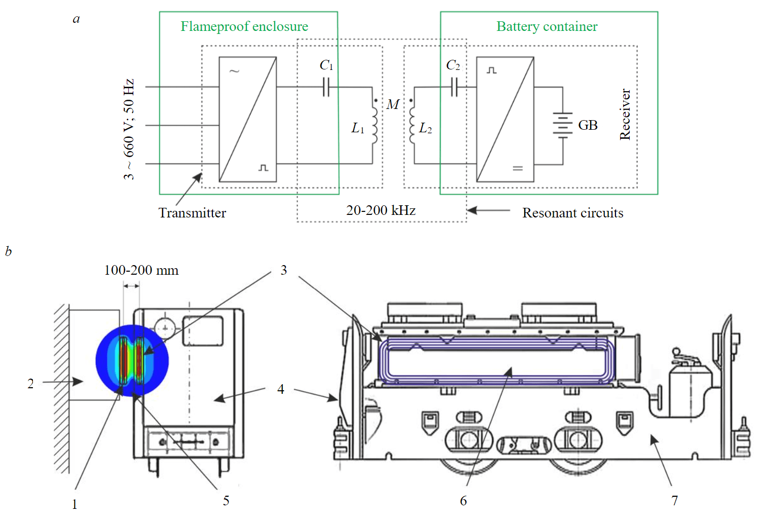
Fig.1. Wireless charging system for mining electric locomotive “A-5.5-600-U5”: a – block diagram of the wireless charger; b – possible design 1 – transmitting coil; 2 – transmitter enclosure; 3 – receiving coil; 4 – mining electric locomotive; 5 – charging area; 6 – battery container; 7 – frame
Table 1
Hierarchy of solutions
|
First level |
Second level |
||
|
Designation |
Component of the wireless charging system |
Designation |
Circuit solutions |
|
R1 |
High-frequency inverter |
R1.1 |
Matrix converter |
|
R1.2 |
Current-source inverter |
||
|
R1.3 |
Voltage-source inverter |
||
|
R2 |
DC power converter |
R2.1 |
Diode-bridge rectifier |
|
R2.2 |
Active rectifier |
||
|
R2.3 |
Synchronous rectifier |
||
|
R3 |
Compensation topology |
R3.1 |
Series |
|
R3.2 |
Parallel |
||
|
R3.3 |
Hybrid |
||
|
R4 |
Coil type |
R4.1 |
Circular |
|
R4.2 |
Rectangular |
||
|
R4.3 |
Polarized |
||
For high-frequency inverters R1, there is a high variability of circuitry [24, 25]. They are divided into single-stage and dual-stage power converters. The first ones are matrix converters R1.1 and, as there is no intermediate DC link, they have smaller dimensions and higher total efficiency, but the second-order harmonic appears in the receiving circuit, and, consequently, in the battery charging current. Dual-stage converters, despite some loss in weight and overall dimensions, are much more common, since they are used in a wide range of electrical applications, are well debugged and, in addition, have a high potential for optimizing components and parameters, which can level out the difference in efficiency.
In the dual-stage converters, a current-source inverter R1.2 and a voltage-source inverter R1.3 can be employed. The current-source inverters are usually used for the resonant circuits with parallel compensation topology to mitigate current loading and overvoltages, as well as improve the harmonic content of the transmitting current. Compared to other inverter types, they have a lower current stress on all elements, which leads to lower losses in semiconductor switches. This effect is achieved by using a powerful inductor with large dimensions, so such inverters are inferior voltage-source inverters in terms of weight and overall dimensions.
The DC power converter R2 provides the battery charging current and can be a diode-bridge rectifier R2.1 or an active rectifier R2.2, or a synchronous rectifier 2.3. The diode-bridge rectifier is the most common due to its simplicity and minimal dimensions, however, in a wide load range due to its nonlinearity, it provokes a significant decrease in the coupling coefficient [26]. Diodes in the active rectifier are replaced by transistors, and due to the adjustable phase shift, this rectifier provides impedance matching but requires a relatively complex control system [27, 28]. An alternative to the active rectifier that also provides impedance matching is the synchronous rectifier, consisting of a diode bridge and a boost converter [29]. The active rectifier and the synchronous rectifier cannot operate without a closed-loop control system.
The compensation topology R3 of the resonant circuit differs in the placement of additional inductors and capacitors relative to the transmitting and receiving coils [30, 31]. The basic compensation topologies are series R3.1 and parallel R3.2. Series topology is usually used in conjunction with voltage sources. It has a higher power transfer coefficient and less sensitivity to misalignment between the transmitting and receiving coils [32]. Parallel topology is typically used with current sources and requires an additional series inductor, which makes the system more complex. This topology provides more impedance and is easier to control.
In addition to series and parallel, there are also hybrid topologies R3.3 that can have a parallel compensating capacitor in the transmitting circuit and a series one in the receiving circuit or the use of several compensating inductors and capacitors simultaneously in different connection options. They are used to reduce the misalignment sensitivity [33], to provide switching the battery charging mode from current charging to voltage charging [34], to reduce sensitivity to load changes [35], and in other specific tasks.
The coil type R4 for transmitting and receiving coils is fundamentally divided into non-polarized coils (circular R4.1 and rectangular R4.2), and polarized coils R4.3 (solenoid, flat bipolar coil, “double D”, etc.) [36, 37]. Circular ones provide the highest coupling coefficient and efficiency for a comparable active mass and coil area. Rectangular coils are somewhat inferior to circular, but they are better than polarized coils with respect to leakage flux in both vertical and lateral directions. Polarized ones are more resistant to misalignment of the coils compared to circular and rectangular coils.
Since it is difficult to quantify the described hierarchy of solutions, to compose paired comparison matrixes (PCM) the seventeen-digit Saaty scale* was used. In addition to the above characteristics of the particular circuit solutions, the design limitations were also taken into account. For example, if the compared solutions differ in size, given the volume limit of the flameproof enclosure it becomes necessary to reduce the power for the larger alternative. The PCMs for the first-level solutions R1-R4 relating to criterion K1 are composed, and the local priorities were found.
Let us consider in detail the PCM for the high-frequency inverter R1 relating to the surface temperature K1. Since the second-level solution R1.1 has smaller dimensions and higher efficiency, the heating losses are less, consequently, the surface temperature is lower than for R1.2 and R1.3. Solutions R1.2 and R1.3 were taken as equivalent. Thus,
Arguing similarly, the PCMs for R2-R4 relating to K1 were obtained:
All PCMs are highly aligned. The consistency indices kCIK1R1–kCIK1R4 and the consistency ratios kCRK1R1–kCRK1R4 for the given PCMs are:
which indicates the correctness of the assessment made.
The general solution R comprises a combination of one second-level solution from each of the first-level solutions R1-R4. Taking that the paired comparison is the ratio of the weights for the considered solutions relating to a particular criterion, and the weight of the combinational solution is determined by the product of the weights of its constituents, the PCM for the general solution R is defined as the Kronecker product of the PCMs for R1, R2, R3, and R4:
For clarity, let us expand the Kronecker product for the last two factors, which demonstrates the increase in the dimension of matrices:
and therefore СK1,R is an 81×81 matrix.
It should be taken that not all the second-level solutions are compatible. For example, it is inefficient to combine the current-source inverter R1.2 with the series compensation topology R3.1. This means that the hierarchy is not complete, and therefore the assessment of unrealizable combinations and their reciprocals should be replaced by zero. Further, from the obtained PCM, the local priorities vector was calculated
where n = 81.
Similarly, the PCMs СK2,R-СK4,R for general solutions R relating to each criterion K2-K4 were sequentially obtained. Further, based on these PCMs, the local priorities vectors VK2,R-VK4,R were calculated. By combining VK1,R-VK4,R, a general local priorities vector VR was obtained from which the global priorities vector was determined:
where VK was taken equal to [23]
The global priority is the solution where the value of GR(i) is maximum. The obtained global priorities vector has the maximum at the solution with GR(56) = 0.102.
The electrical circuit for this solution is shown in Fig.2. Let us determine the parameters of the circuit elements for the mining electric locomotive “A-5.5-600-U5” that is equipped with a lithium-ion battery “LIAB-70 TRV-BK”. This battery has a nominal voltage of 130 V and a maximum charging current of 270 A. To ensure the system reliability, the nominal charging current was assumed to be 260 A, because short-term in-rush currents are possible. Thus, the equivalent load resistance Rload is equal to 0.5 Ohm.
The parameters of the transmitting and receiving coils were determined based on a given design (according to P.L.Kalantarov and L.A.Tsejtlin). The coils have the same design, which means coil inductances are equal L1 = L2 = L and their internal resistances are equal R1 = R2 = R too. The receiving coil dimensions are 3000×700 mm as the coil is limited by the external surface of the battery container at the electric locomotive. The coil-to-coil distance was assumed to be 100 mm, which sufficiently guarantees a gap between the transmitter when the electric locomotive is moving, on the one hand, but on the other hand, it provides a high enough coupling coefficient. Then the inductances of the transmitting and receiving coils are determined as follows:
where μ0 is the vacuum magnetic permeability; w is the number of turns; b and c are the length and width of the coil outer boundary; r is the width of the winding pitch, which was taken equal to 15 mm. Mutual inductance M is calculated as
where x is the coil-to-coil distance.
Internal resistances are determined as
where S is the cross-section of the winding wire; ρm is its resistivity. The high-voltage high-frequency wire “LELOR-E” with a nominal cross-section of 50 mm2 and a maximum diameter of 15 mm was chosen as the winding wire.
The parameters of the coils and the load at a given resonant frequency determine the capacitance of the compensation topology capacitors. Owing to the resonant circuit symmetry, the capacitances of the transmitting and receiving circuit capacitors are also considered equal, i.e. C1 = C2 = C. It is difficult to determine an analytical expression for C, since the equation describing the resonant frequency fr for the wireless charger shown in Fig.2 has a high dimension. Therefore, the capacitance C was determined by numerical methods using a specially written computer program. The resonant frequency was selected according to the recommendations of the SAE J2954 standard, and fr = 90 kHz.
The design values of the wireless charger electrical parameters are given in Table 2 for a different number of turns. The efficiency design value for the wireless charging system was obtained as the possible maximum over the entire operating frequency range. It does not consider switching and conductive losses in semiconductor switches as well as dielectric losses in capacitors. The efficiency was used only to compare the different designs for one device. The data obtained show that the highest efficiency of the wireless charger is provided for w = 1, and such a design is the simplest. Therefore, the transmitting and receiving coils with the number of turns of 1 were accepted for further consideration. The resulting circuitry and design solution is the basis to analyze the impact on the explosion safety of the electromagnetic field in the charging area of the wireless charger in an explosive gas-and-dust atmosphere.
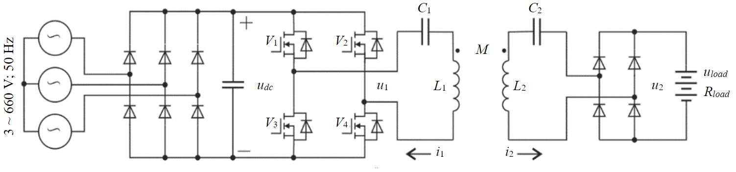
Fig.2. The electrical circuit of the wireless charger
Table 2
The design values of the wireless charger electrical parameters
|
w, u. |
L, μH |
M, μH |
R, Ohm |
C, μF |
η, p.u. |
i2/u1, A/V |
|
1 |
16.6 |
2.7 |
0.003 |
0.162 |
0.994 |
from 0.606 to 2 |
|
2 |
43.7 |
10.5 |
0.006 |
0.058 |
0.988 |
from 0.15 to 1.96 |
|
3 |
78.7 |
23.2 |
0.009 |
0.031 |
0.983 |
from 0.07 to 1.93 |
Determining the conditions for the safe operation
Given the flameproof enclosures for all the components of the wireless charger except the transmitting and receiving coils, the only potential ignition source is the charging area between the coils. Simulation of temperature distribution shows that under normal operation, the high-frequency alternating magnetic field is not a heat source, and the heating of the explosive atmosphere in the charging area occurs mainly due to the laws of heat-and-mass transfer from ohmic losses in winding wires [38, 39]. But the situation fundamentally changes if there is a foreign metal object between the coils as in this object the eddy currents are induced. Since the specific heat capacity of metals is generally low, the heating losses from the eddy currents can significantly increase the surface temperature.
To evaluate the ignition risk from the foreign metal object heating, it was assumed that in the metal object with the limited volume, the heating power from eddy currents cannot exceed the power of the inducing magnetic field. Given that the high-frequency alternating magnetic field at each point of the charging area changes sinusoidally with an angular frequency ω, and the magnetic induction distributes over the metal object volume V is uniform, the power of the magnetic field converting into heating power is determined as follows
where µ is the magnetic permeability; Bmaxis the magnetic induction amplitude.
The temperature to which the foreign metal object will be heated is determined by thermal equilibrium. Assuming that the thermal field potential is uniformly distributed over the metal object volume, and the heat is transferred due to natural convection, the temperature exceedance over the ambient temperature is determined as (according to S.S.Kutateladze, V.M.Borishanskiy)
where α is thermal diffusivity, depending on the shape and size of the heated metal object, as well as the product of the Prandtl number Pr and the Grashof numberGr.
The temperature exceedance τ was determined based on GOST 31610.0–2019 standard. It precepts that for equipment of group I, i.e. for equipment in explosive atmospheres of underground mines, the maximum surface, on which coal dust is unlikely to be deposited in the form of a layer, the temperature should be no higher than 450°C, and the ambient temperature is taken equal to +40°C.
Analyzing (1) and (2) together, we determine the limiting value of the magnetic induction amplitude as:
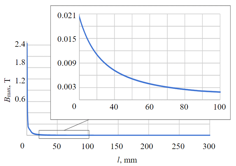
Fig.3. The limiting value of the magnetic induction amplitude
where A1, A2, A3 are coefficients depending on air temperature; l is the length of the cube edge.
If the magnetic induction is lower than Bmax, the maximum possible surface temperature of the foreign metal object heated by the eddy currents does not exceed 450°C with a guarantee.
The dependence of Bmax on l for the conditions under consideration is shown in Fig.3. Considering that the distance x was assumed to be 100 mm, the length of the cube edge of the foreign metal object cannot exceed this value. Consequently, the magnetic induction amplitude of the wireless charger at any point in the charging area should not exceed 1.929 mT. It is possible to determine whether this condition is met for the wireless charging system under consideration using computer simulation.
Complex computer model
Computer simulation of the wireless charger under consideration can determine the magnetic induction of the magnetic field at the charging area in a 3D formulation, taking into account the physical properties of the transmitting and receiving coils' materials and the environment. Using a finite element model in combination with a dynamic model of the wireless charger electrical circuit describes the transients in the system, including changes in the electromagnetic radiation energy. Such a complex computer model was implemented employing the MatLab Simulink and Altair Flux.
The MatLab Simulink model of the wireless charger has the following assumptions: the rectifier in the dual-stage voltage-source inverter is ideal, and the DC link voltage is constant; semiconductor switches of the inverter and the rectifier are idealized and do not describe their switching losses and conductive losses; the compensation topology capacitors are idealized and do not describe their dielectric losses. The model is made using the SimPowerSystems library which ensures a high level of its adequacy since the elements of this library have been widely tested (Fig.4).
The Altair Flux model of the transmitting and receiving coils and the charging area is based on a 3D drawing consisting of two elements shaped as curved cylinders with a cross-section of 50 mm2 which are rectangular in plan with dimensions of 3000×700 mm, placed at the distance of 100 mm between the cylinders axes with no misalignment. In the simulation, a dynamic mesh was used with automatic selection of finite elements size, providing an error of no more than 1·10-6 T at each calculation step.
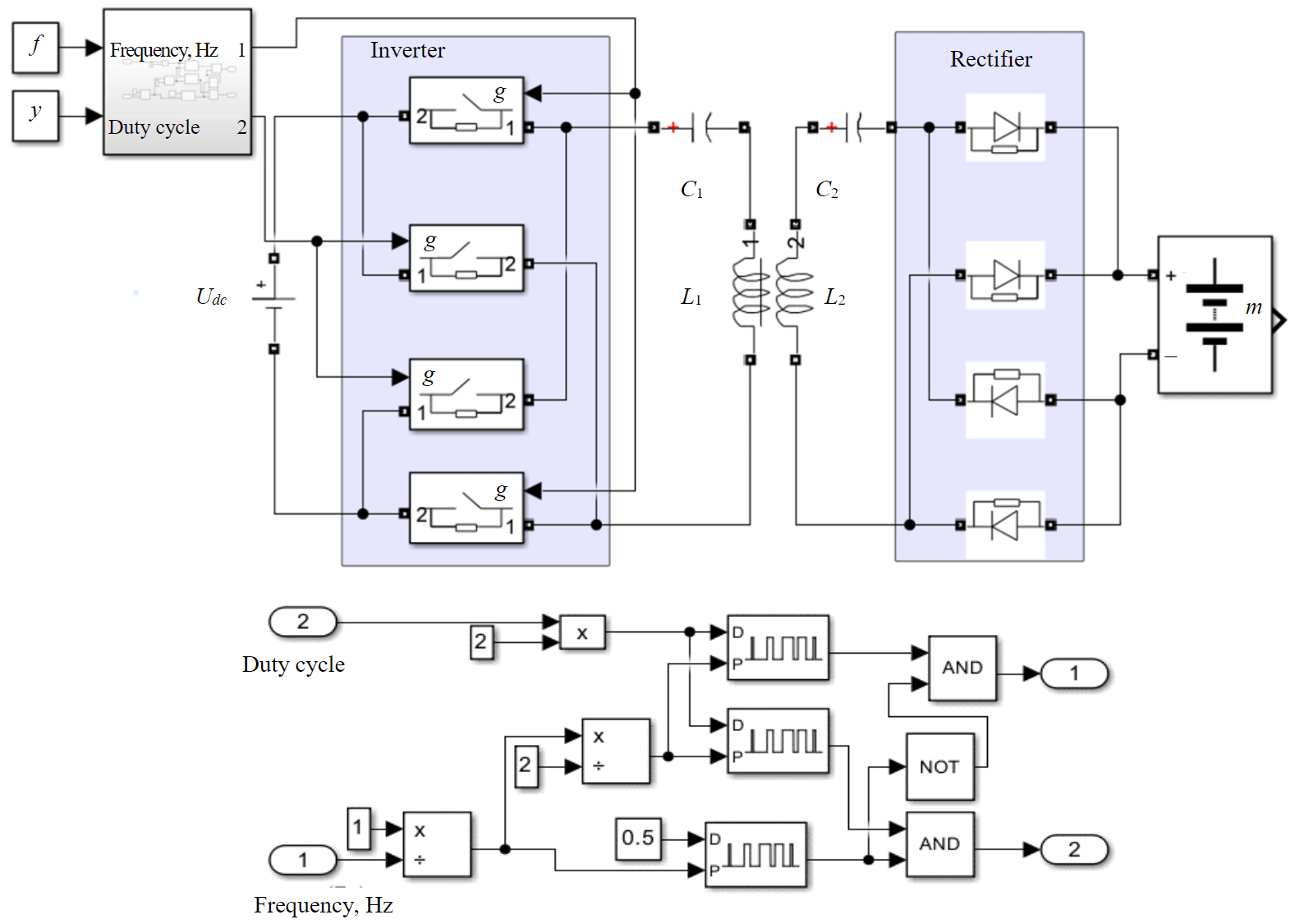
Fig.4. The MatLab Simulink model of the wireless charger
Results and discussion
Prototype test
To demonstrate the feasibility of the wireless charger with the described design and to confirm the adequacy of the computer model used, the electric locomotive prototype was made on a scale of 1:10, equipped with the wireless charging system having the following parameters: L1 = L2 = 100 μH; M = 10 μH; R1 = R2 = 0.01 Ohm; C1 = C2 = 33 nF; Rload = 6 Ohm (Fig.5). The high-frequency inverter is built on IRFP90N20DPBF transistors with the nominal voltage of 200 V and the nominal current of 94 A, and the DC power converter is based on Schottky diodes of VS 80CPQ150-N3 with the nominal current of 40 A and the nominal voltage of 150 V. The Delta Elektronika SM330-AR-22 DC power supply with a power of 3300 W was used as a power source. A Fluke TiS20 thermal imager and a DS1074Z-S oscilloscope were used as measuring equipment for the prototype test.
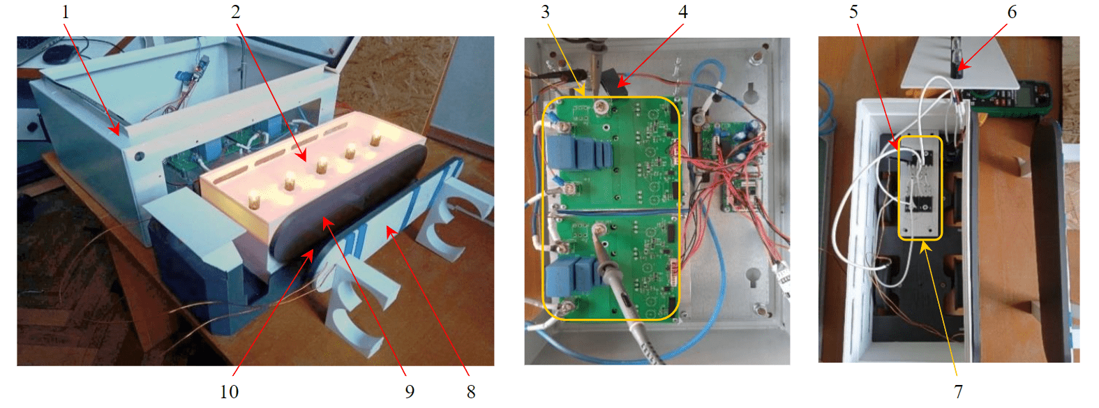
Fig.5. The electric locomotive prototype equipped with the wireless charging system 1 – transmitter; 2 – electric locomotive prototype; 3 – high-frequency inverter; 4 – transmitting circuit capacitor; 5 – receiving circuit capacitor; 6 – load; 7 – DC power converter; 8 – transmitting coil; 9 – receiving coil; 10 – charging area
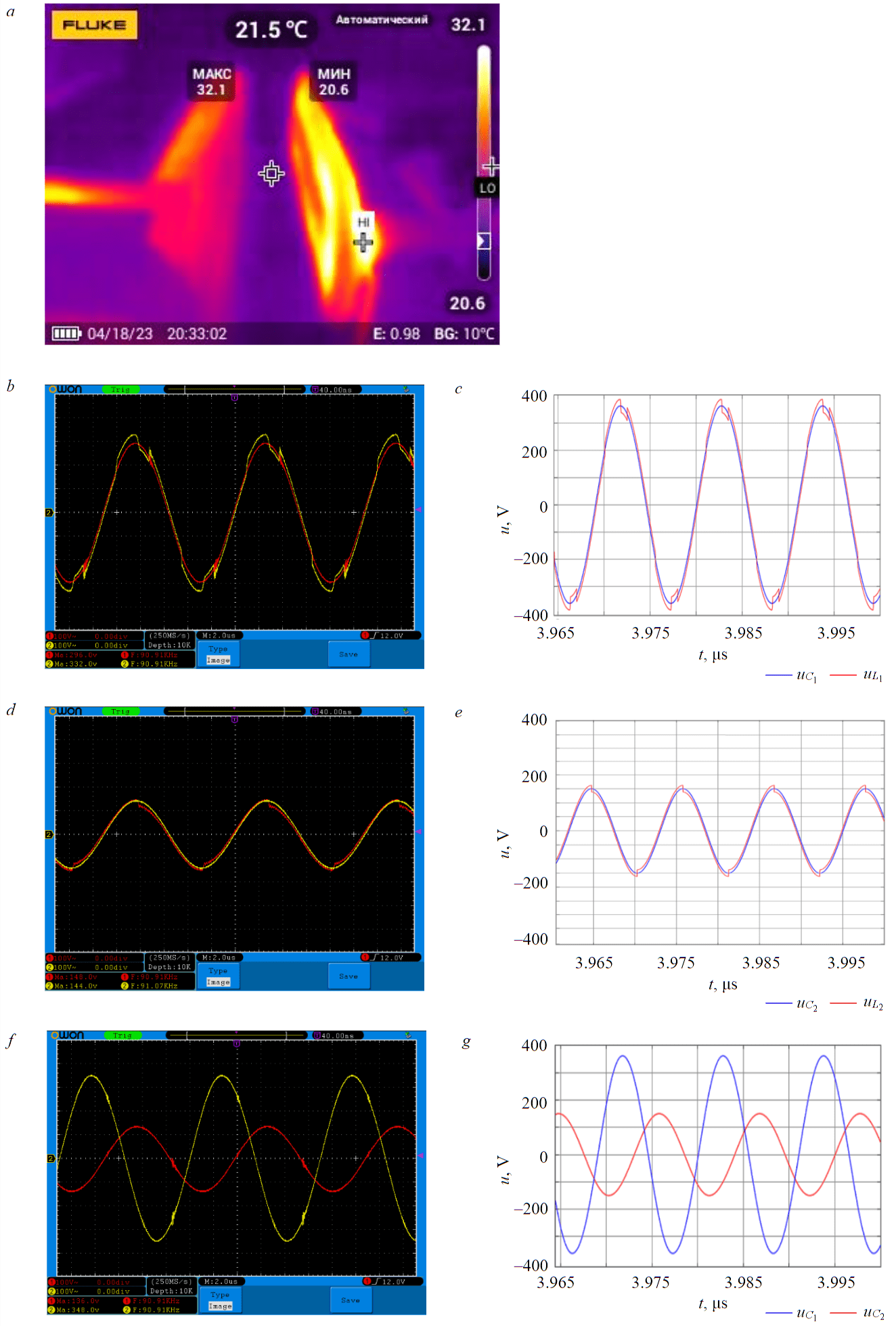
Fig.6. The prototype test results: a – thermogram; b –experiment uL1, uC1; c –simulation uL1, uC1; d – experiment uL2, uC2; e – simulation uL2, uC2; f – experiment uC1, uC2; g – simulation uC1, uC2
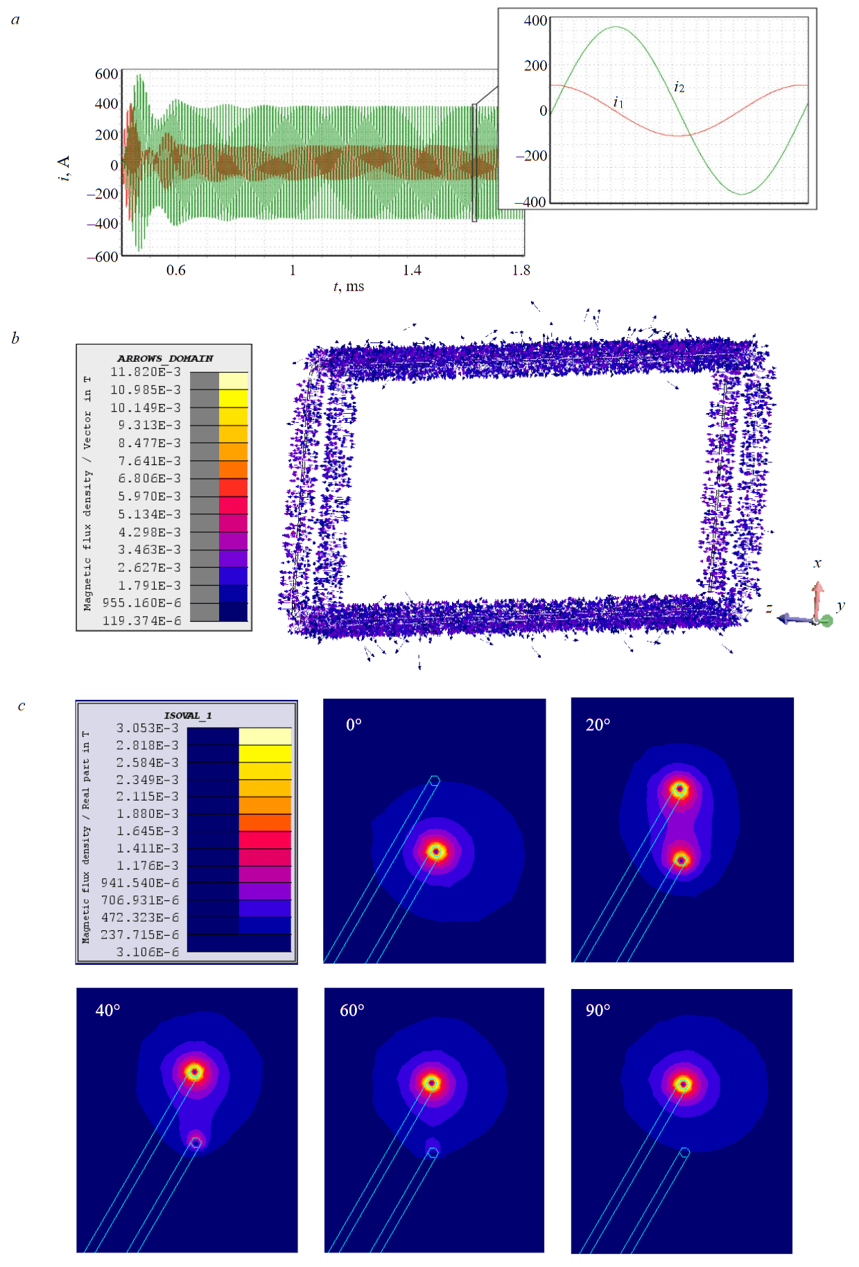
Fig.7. Simulation results: a – transients of i1 and i2; b – the field of the magnetic induction distribution vectors for a phase value of 20°; c – distribution of magnetic induction in the winding wire vicinity for phase values of 0°, 20°, 40°, 60° and 90°
The prototype test was carried out at a power supply voltage of 24 V, an operating frequency of 91 kHz, and a duty cycle of 0.28. During the tests, voltages uL1, uC1, and uL2, uC2 were measured on the coils and the capacitors of the transmitting and receiving circuits respectively. The same parameters for the same conditions were simulated using MatLab Simulink. The obtained results are shown in Fig.6.
The thermogram demonstrates the operation of the wireless charging system, and it is an indirect tool showing the magnetic field distribution between the coils (Fig.6, a). The heating source at the charging area is the heating losses in the coils' wire caused by flowing currents as the central region of the coils has a significantly lower temperature.
The oscillograms show the measured voltages, where the division values are 100 V on the voltage scale and 2 μs on the time scale (Fig.6, b, d, f). The corresponding voltages obtained by simulation are shown in Fig.6, c, e, g. Comparison of the simulation and experiment results indicates that, except for micro transients, when semiconductor switches activate, there is a quantitative and qualitative correspondence of the considered voltages in both the amplitude and the phase. The maximum discrepancy between the simulation and experiment results is 3.28% which indicates a high adequacy of the computer model (see Fig.4). This result justifies using the above-described complex computer model to analyze the explosion safety of the wireless charging system for the mining electric locomotive “A-5.5-600-U5”
Simulation results
The complex computer model gives the high-frequency field density distribution in the charging area of the wireless charging system for mining electric locomotive “A-5.5-600-U5”. The simulation was carried out in two stages. In the first stage, the transients were simulated, including the current of the transmitting and receiving coils that were subsequently used in the second stage as the input data for the magnetic field simulation.
When working with the model in MatLab Simulink, the operating frequency and duty cycle were set at the input of the system. It should be noted that when the wireless charger parameters were calculated the resonant frequency was set at 90 kHz. Hence, the receiving current i2 has the maximum at this frequency, where in case the resonant circuit input voltage u1 is constant, the current transfer coefficient i2/u1=2 A/V. The efficiency of wireless power transfer at this frequency is 0.988, while the theoretical maximum is 0.994. Therefore, it is advisable to set the operating frequency differing from the resonant one to find a balance between striving for maximum efficiency and providing the required charging current.
In the case under consideration, the charging current is 260 A, so the current amplitude of i2 is 368 A. The theoretical minimum of the current transfer coefficient i2/u1 = 0.606 A/V, hence the voltage amplitude of u1 should be no lower than 607 V. As the effective phase to neutral voltage of three-phase mains is 660 V, the DC link voltage is 891 V, and the required charging current can be provided at any operating frequency. Based on this, the operating frequency was set at 97.1 kHz where the efficiency has the maximum. The duty cycle that provides the resonant circuit input voltage of 607 V is 0.68.
The currents i1 and i2 obtained from the MatLab Simulink model for the described conditions are shown in Fig.7, a. The amplitudes of these currents, as well as the phase shift between them, were used as the input data for the Altair Flux model that determines the magnetic induction distribution vectors in the charging area during the period of current change. The simulation results of the magnetic field distribution in the charging area are shown in Fig.7, b, c. They show that the induction of the high-frequency magnetic field outside the winding wire vicinity of the transmitting and receiving coils is negligible and is equal to zero in the center of the 3000×700 rectangle. This indicates fairly high electromagnetic compatibility and safety for people according to the criteria of SanPiN 1.2.3685-21 sanitary norms.
Analyzing the magnetic field in the winding wire vicinity, it was found that the maximum magnetic induction amplitude outside the winding wire is 3.548 mT, whereas as early as the distance of 18 mm, the magnetic induction amplitude does not exceed 1.929 mT. Since it was initially supposed to use encapsulation as the coils' protection, with an insulation layer of 20 mm thick, the ignition risk could be neglected for any metal object between the transmitting and receiving coils. As an additional measure, the charging current reduction can be used. It proportionally slows down the charging process of the mining electric locomotive battery but increases the system reliability against explosion.
Conclusion
The study showed that the wireless charging system for mining electric locomotives operating in the gaseous-and-dusty mine is technically feasible and there are such designs and operation modes in which it is explosion safe. The obtained circuitry and design solutions provide the basis for developing the detailed engineering drawings and a set of technological documentation necessary for the manufacture of a prototype wireless charging system and its subsequent submission to the certification authority for proof-of-compliance tests according to the requirements of the Customs Union technical regulation TR CU 012/2011.
The implementation of the considered wireless charging system for mining electric locomotives and other similar mine transports can increase mining efficiency by reducing operating costs that are caused by the need to turn off the batteries and charge them outside the hazardous area. In the case of the implementation of integrating the wireless chargers with the power grid on large mine transport systems, the wireless chargers can be used to adjust the load, ensuring an increase in the energy efficiency of the entire enterprise.
Further study of the wireless charging system under consideration includes modernization of its dynamic model so that switching losses and conduction losses in semiconductor switches as well as dielectric losses in the compensation topology capacitors are taken into account. It allows us to evaluate not just the efficiency of wireless power transfer but the efficiency of the entire wireless charger. It is advisable to analyze the high-frequency field density distribution near the transmitting and receiving coils in the conditions of their misalignment, such as coil-to-coil distance deviations, as well as horizontal and angular misalignment. Additionally, as a development of the system, it is possible to optimize its parameters, as well as to introduce a closed control system.
* Saaty T. Decision making. Analytic hierarchy process. Moscow: Radio and communication, 1993. 320 p.
References
- Weilong Wang, Xiaodong Yang, Jianhong Cao et al. Energy internet, digital economy, and green economic growth: Evidence from China. Innovation and Green Development. 2022. Vol. 1. Iss. 2. N 100011. DOI: 1016/j.igd.2022.100011
- Jie Xiong, Shuyan Zhao, Yan Meng et al. How latecomers catch up to build an energy-saving industry: The case of the Chinese electric vehicle industry 1995-2018. Energy Policy. 2022. Vol. 161. N 112725. DOI: 1016/j.enpol.2021.112725
- Zhifeng Que, Shixue Wang, Weiyi Li. Potential of energy saving and emission reduction of battery electric vehicles with two type of drivetrains in China. Energy Procedia. 2015. Vol. 75, p. 2892-2897. DOI: 1016/j.egypro.2015.07.584
- Hong-Mei Deng, Yun-Peng Zhang, Jing Li et al. Research on energy saving potential and countermeasures in China’s transport sector. Energy Reports. 2022. Vol. 8. S. 6, p. 300-311. DOI: 1016/j.egyr.2022.03.098
- Bibak B., Tekiner-Mogulkoc H. Influences of vehicle to grid (V2G) on power grid: An analysis by considering associated stochastic parameters explicitly. Sustainable Energy, Grids and Networks. 2021. Vol. 26. N 100429. DOI: 10.1016/j.segan.2020.100429
- Gough R., Dickerson C., Rowley P., Walsh C. Vehicle-to-grid feasibility: A techno-economic analysis of EV-based energy storage. Applied Energy. 2017. Vol. 192, p. 12-23. DOI: 10.1016/j.apenergy.2017.01.102
- Laiqing Xie, Yugong Luo, Donghao Zhang et al. Intelligent energy-saving control strategy for electric vehicle based on preceding vehicle movement. Mechanical Systems and Signal Processing. 2019. Vol. 130, p. 484-501. DOI: 10.1016/j.ymssp.2019.05.027
- Augello A., Gallo P., Sanseverino E.R. et al. Certifying battery usage for V2G and second life with a blockchain-based framework. Computer Networks. 2023. Vol. 222. N 109558. DOI: 10.1016/j.comnet.2023.109558
- Mastoi M.S., Shenxian Zhuang, Munir H.M. et al. An in-depth analysis of electric vehicle charging station infrastructure, policy implications, and future trends. Energy Reports. 2022. Vol. 8, p. 11504-11529. DOI: 10.1016/j.egyr.2022.09.011
- Mohammed S.A.Q., Jin-Woo Jung. A Comprehensive State-of-the-Art Review of Wired/Wireless Charging Technologies for Battery Electric Vehicles: Classification/Common Topologies/Future Research Issues. IEEE Access. 2021. Vol. 9, p. 19572-19585. DOI: 10.1109/ACCESS.2021.3055027
- Cirimele V., Diana M., Freschi F., Mitolo M. Inductive power transfer for automotive applications: state-of-the-art and future trends. IEEE Transactions on Industry Applications. 2018. Vol. 54. N 5, p. 4069-4079. DOI: 10.1109/TIA.2018.2836098
- Jian-guo Li, Kai Zhan. Intelligent Mining Technology for an Underground Metal Mine Based on Unmanned Equipment. Engineering. 2018. Vol. 4. Iss. 3, p. 381-391. DOI: 10.1016/j.eng.2018.05.013
- Jäderblom N. From Diesel to Battery Power in Underground Mines. A Pilot Study of Diesel Free LHDs: Master of Science Thesis in Industrial Design Engineering. Luleå: Luleå University of Technology, 2017, p. 75.
- Semykina I., Zavyalov V., Dubkov E., Veliliaev A.-H. On the possibility of wireless battery charging in a gaseous-and-dusty mine. E3S Web of Conferences. 2021. Vol. 303. N 01032. DOI: 10.1051/e3sconf/202130301032
- Borisov S.V., Koltunova E.A., Kladiev S.N. Traction asynchronous electric drive of mine electric locomotivesimulation model structure improvement. Journal of Mining Institute. Vol.247, p. 114-121. DOI: 10.31897/PMI.2021.1.12
- Songyan Niu, Hang Yu, Shuangxia Niu, Linni Jian. Power loss analysis and thermal assessment on wireless electric vehicle charging technology: The over-temperature risk of ground assembly needs attention. Applied Energy. 2020. Vol. 275. N 115344. DOI: 10.1016/j.apenergy.2020.115344
- Lijuan Xiang, Ze Zhu, Jindong Tian, Yong Tian. Foreign Object Detection in a Wireless Power Transfer System Using Symmetrical Coil Sets. IEEE Access. 2019. Vol. 7, p. 44622-44631. DOI: 10.1109/ACCESS.2019.2908866
- Ahmad A., Alam M.S., Chabaan R. A Comprehensive Review of Wireless Charging Technologies for Electric Vehicles. IEEE Transactions on Transportation Electrification. 2018. Vol. 4. N 1, p. 38-63. DOI: 10.1109/TTE.2017.2771619
- Abou Houran M., Xu Yang, Wenjie Chen. Magnetically Coupled Resonance WPT: Review of Compensation Topologies, Resonator Structures with Misalignment, and EMI Diagnostics. Electronics. 2018. Vol. 7. Iss. 11. N 296. DOI: 10.3390/electronics7110296
- Foote A., Onar O.C. A review of high-power wireless power transfer. IEEE Transportation Electrification Conference and Expo (ITEC), 22-24 June 2017, Chicago, USA. IEEE, 2017, p. 234-240. DOI: 10.1109/ITEC.2017.7993277
- Semykina I.Yu., Zavyalov V.M., Krylov V.N. Research of the Laboratory Prototype for the Battery Charging System Based on Wireless Power Transfer. 21th International Conference of Young Specialists on Micro/Nanotechnologies and Electron Devices (EDM), 29 June – 3 July 2020, Chemal, Russia. IEEE, 2020, p. 324-330. DOI: 10.1109/EDM49804.2020.9153521
- Qizhi Liu. Identifying and correcting the defects of the Saaty analytic hierarchy/network process: A comparative study of the Saaty analytic hierarchy/network process and the Markov chain-based analytic network process. Operations Research Perspectives. 2022. Vol. 9. N 100244. DOI: 10.1016/j.orp.2022.100244
- Semykina I.Yu., Dubkov E.A., Zav'yalov V.M. Substantiation of criteria for technical solutions evaluating for wireless charging systems for mining electric vehicles. Sbornik trudov VIII Mezhdunarodnoi nauchno-prakticheskoi konferentsii “Perspektivy innovatsionnogo razvitiya ugolnykh regionov Rossii”, 13-14 aprelya 2022 g., Prokopevsk, Rossiya. Prokopevsk: filial KuzGTU v g.Prokopevske, 2022. С. 88-93.
- Huynh P.S., Ronanki D., Vincent D., Williamson S.S. Overview and Comparative Assessment of Single-Phase Power Converter Topologies of Inductive Wireless Charging Systems. Energies. 2020. Vol. 13. Iss. 9. N 2150. DOI: 10.3390/en13092150
- Kripalakshmi T., Deepa T. A Comprehensive Review of High-frequency Transmission Inverters for Magnetic Resonance Inductive Wireless Charging Applications in Electric Vehicles. IETE Journal of Research. 2021, p. 1-11. DOI: 10.1080/03772063.2021.1905089
- Bing Cheng, Liangzong He, Le Li et al. Improved wireless power transfer system utilizing a rectifier with nonlinear resistance compression characteristic. Applied Energy. 2023. Vol. 331. N 120365. DOI: 10.1016/j.apenergy.2022.120365
- Zhong W.X., Hui S.Y.R. Maximum Energy Efficiency Tracking for Wireless Power Transfer Systems. IEEE Transactions on Power Electronics. 2015. Vol. 30. N 7, p. 4025-4034. DOI: 10.1109/TPEL.2014.2351496
- Di Capua G., Femia N., Lisi G. Impact of losses and mismatches on power and efficiency of Wireless Power Transfer Systems with controlled secondary-side rectifier. Integration. 2016. Vol. 55, p. 384-392. DOI: 10.1016/j.vlsi.2016.04.005
- Hongchang Li, Jie Li, Kangping Wang et al. A Maximum Efficiency Point Tracking Control Scheme for Wireless Power Transfer Systems Using Magnetic Resonant Coupling. IEEE Transactions on Power Electronics. 2015. Vol. 30. N 7, p. 3998-4008. DOI: 10.1109/TPEL.2014.2349534
- Shuyu Cao, Htet Ye Yint Naing, Naayagi R.T. et al. Wireless Charging Resonant Converter Topology Study Based On Analytical Design Computation. 3rd International Conference on Energy, Power and Environment: Towards Clean Energy Technologies, 5-7 March 2021, Shillong, Meghalaya, India. IEEE, 2021, p. 1-6. DOI: 10.1109/ICEPE50861.2021.9404462
- Mude K.N., Aditya K. A Comprehensive Review and Analysis of Two-Element Resonant Compensation Topologies for Wireless Inductive Power Transfer Systems. Chinese Journal of Electrical Engineering. 2019. Vol. 5. N 2, p. 14-31. DOI: 10.23919/CJEE.2019.000008
- Jayalath S., Khan A. Design, Challenges, and Trends of Inductive Power Transfer Couplers for Electric Vehicles: A Review. IEEE Journal of Emerging and Selected Topics in Power Electronics. 2021. Vol. 9. N 5, p. 6196-6218. DOI: 10.1109/JESTPE.2020.3042625
- Jianwei Mai, Yijie Wang, Yousu Yao, Dianguo Xu. Analysis and Design of High-Misalignment-Tolerant Compensation Topologies With Constant-Current or Constant-Voltage Output for IPT Systems. IEEE Transactions on Power Electronics. 2021. Vol. 36. N 3, p. 2685-2695. DOI: 10.1109/TPEL.2020.3014687
- Xiaohui Qu, Hongdou Han, Siu-Chung Wong et al. Hybrid IPT Topologies With Constant Current or Constant Voltage Output for Battery Charging Applications. IEEE Transactions on Power Electronics. 2015. Vol. 30. N 11, p. 6329-6337. DOI: 10.1109/TPEL.2015.2396471
- Siqi Li, Weihan Li, Junjun Deng et al. A Double-Sided LCC Compensation Network and Its Tuning Method for Wireless Power Transfer. IEEE Transactions on Vehicular Technology. 2015. Vol. 64. N 6, p. 2261-2273. DOI: 10.1109/TVT.2014.2347006
- Marques E.G., Mendes A.M.S. Optimization of transmitter magnetic structures for roadway applications. IEEE Applied Power Electronics Conference and Exposition (APEC), 26-30 March 2017, Tampa, USA. IEEE, 2017, p. 959-965. DOI: 10.1109/APEC.2017.7930812
- Bandyopadhyay S., Venugopal P., Jianning Dong, Bauer P. Comparison of Magnetic Couplers for IPT-Based EV Charging Using Multi-Objective Optimization. IEEE Transactions on Vehicular Technology. 2019. Vol. 68. N 6, p. 5416-5429. DOI: 10.1109/TVT.2019.2909566
- Chunbo Zhu, Chaoye Fu, De'an Wang et al. Thermal Simulation and Optimization Study for Magnetic Coupler of Static Electric Vehicle Wireless Power Transfer Systems. 22nd International Conference on Electrical Machines and Systems (ICEMS), 11-14 August 2019, Harbin, China. IEEE, 2019, p. 1-4. DOI: 10.1109/ICEMS.2019.8921715
- Chunming Wen, Qing Xu, Minbo Chen et al. Thermal Analysis of Coupled Resonant Coils for an Electric Vehicle Wireless Charging System. World Electric Vehicle Journal. 2022. Vol. Iss.8. N 133. DOI: 10.3390/wevj13080133