
A complex model of a drilling rig rotor with adjustable electric drive
- 1 — Ph.D., Dr.Sci. Professor National University of Oil and Gas “Gubkin University” ▪ Orcid
- 2 — Ph.D. Head of Department National University of Oil and Gas “Gubkin University” ▪ Orcid
- 3 — Student National University of Oil and Gas “Gubkin University” ▪ Orcid

Abstract
A modified mathematical model of an asynchronous electric drive of the rotor – a drill string – a bit – a rock is considered and implemented, which develops and generalizes the results of previously performed studies. The model includes the following subsystems: a model of an asynchronous drive with vector control; a model of formation of the resistance moment at the bottom of the bit, taking into account the peculiarities of the interaction between the bit and the rock; a model of a multi-mass mechanical part that takes into account the deformation of the drill string; subsystem for the drilling rig energy-technological parameters formation. The integrated model makes it possible to calculate and evaluate the selected drilling modes, taking into account their electro-mechanical, energy and technological efficiency and the dynamics of drilling processes. The performed computer simulation of drilling modes confirmed the possibility of a stick-slip effect accompanied by high-frequency vibrations during bit stops, which may change the direction of rotation of the bit, its accelerated wear and unscrewing of the drilling tool. Long bit stops lead to a significant decrease in the average bit rotation speed, which can explain the decrease in the ROP and increase in energy consumption when drilling in the zone of unstable bit rotation. The model can be used as a base for further improvement of rotary drilling control systems.
None
Introduction
The drilling rig rotor with electric drive is distinguished by a complex mechanical part (Fig.1). The rotation of the motor rotor through the transmission device is transmitted to the rotor of the drilling rig and through the drill pipes column (DPC) – to the bit. By drilling rig rotor moment, applied to the top of the string, and the bit moment of resistance, applied to the bottom of the string, drill pipes are deformed and twisted at a certain angle, the value of which depends on the length, diameter and elastic properties of the string and can reach tens of revolutions. During the drilling process, the twist angle can remain practically unchanged, while the bit rotates uniformly. When the angle of twist changes during the drilling process, an uneven, unstable rotation of the bit occurs (stick-slip effect) with long stops, immersions in the rock and bit breaks, as well as the appearance of torsional and longitudinal self-oscillations of the drilling tool [1]. This mode occurs when working with PDC bits of the cutting-attrition type especially often (more than 50 % of the drilling time). Unstable bit rotation modes can prevail during well drilling [2, 3], reducing the energy efficiency of drilling and accelerating the drilling tools wear [4, 5]. This work is dedicated to creation a complex model of a drilling rig with an asynchronous electric drive of the rotor – a drill string – a bit – rock, simulating the main processes of electric rotary drilling, with a set of characteristics for analyzing the electromechanical, energy and technological efficiency of drilling modes. The results of the work develop the earlier studies results [6-8].
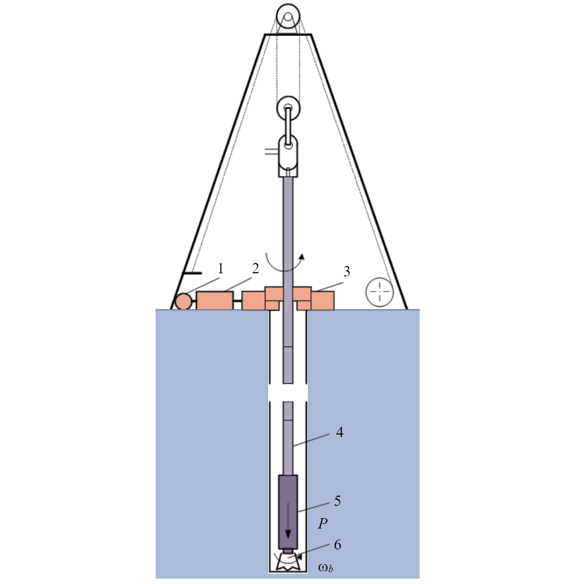
Fig.1. Drilling rig scheme 1 – rotor drive; 2 – transmission devices; 3 – drilling rig rotor; 4 – drill pipe string; 5 – column bottom layout; 6 – drilling bit
Methodology
Modeling of the asynchronous the drilling rig electric drive was carried out in the Matlab Simulink environment. The block diagram of the base model is shown in Fig.2. The model includes the following main subsystems: IM-Subsystem – a model of an asynchronous motor with a vector control system based on PI flux linkage, speed and current controllers; Meh-Subsystem – a model of the mechanical part of the electric drive, including a motor rotor, a drilling rig rotor, transmission mechanisms and a drill string; dual-mass model of the rotor drive mechanical part is shown in Fig.3; Tb0-Subsystem, Tb1-Subsystem, Tb-Subsystem – subsystems of the drag moment model on the bit; ETP-Subsystem – a subsystem for the formation of energy-technological drilling parameters.
The main nominal parameters of the AFD series rotor drive asynchronous motor are as follows: power 1000 kW; voltage 660 V; current 1075 A; torque 9620 N·m; speed 993 rpm.
“Motor modeling was carried out in coordinates (x, y), the rotation speed of which is equal to the rotation speed of the stator field (ωк = ω1), with the base voltage vector (uSx = U1; uSy = 0)” [7].The mathematical model of the engine is represented by the following system of equations in operator form:
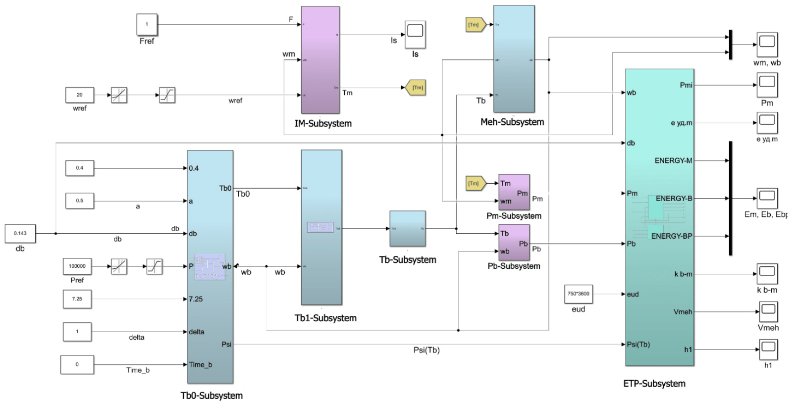
Fig.2. Structural diagram of the drilling rig rotor with asynchronous drive
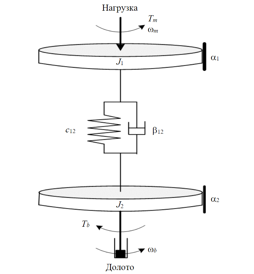
Fig.3. Dual-mass model of rotor drive mechanical part
where ω1 = 104.7 s–1 is the synchronous speed; p = 3 is the pole pairs number; ωm – motor shaft speed; ψRx, ψRy – rotor flux linkage along the axes x, y; ψSx, ψSy – stator flux linkage along the axes x, y; iRx, iRy – rotor currents along the axes x, y; iSx, iSy – stator currents along the axes x, y; Tm – motor moment; s – operator; RR, RS – rotor and stator active resistances; Lm, LR, LS – rotor and stator mutual and self-inductance; TR = LR/RR – rotor time constant; – stator time constant; r = RS + + ; kr = Lm/LR; = LS – – /LR.
The parameters included in the equations of system (1) are as follows: RR = 0.00267 Ω; r = 0.939 Ω; kr = = 0.939; = 0.00034 H; = 0.068 s; ТR = 1.064 s.
Determination of motor parameters – active resistances, inductances and time constants, as well as para-meters of PI controllers – was carried out according to the following methods [8-10]. In the parallel form of writing the transfer function expression, the parameters of the flux linkage PI controller were Рψ = 410, Iψ = 14. The PI controllers parameters of speed and current, tuned to the technical optimum were: Рω = 166, Iω = 16.5 (for speed controller) and PI = 3, II = 10 (for current controller).
The mechanical part of the electric drive is implemented in the form of multi-mass (from two to four masses) equivalent systems in the Meh-Subsystem block. The initial data for modeling corres-pond to a drilling rig of the BU-5000/320 type. The length of the drill pipe string is assumed to be 3000 m, the pipe diameter dt = 0.127 (wall thickness 0.09 m), the layout of the bottom of the DPC is made of UBT pipes 203×80 (90 m), the bit diameter dt = 0.295 m (PDC bit 295.3FD257M-A27). The mathematical model of a dual-mass mechanical system in operator form is represented by the follo-wing system of equations:
where ωb(t) – bit rotation speed, rad/s; Tr1 – moment of resistance of the first mass, N·m; Tb – moment of resistance applied to the second mass (torque on the bit), N·m; Tr1 – first mass resistance moment, determined by the product of the external viscous friction a coefficient on engine speed ωm.
Estimated moments of inertia of the two-mass system elements: J1 = 66.5, J2 = 12.5 kg·m2; stiffness factor с12 = 22.8 N·m/rad; viscous friction coefficient β12 = 0.06 N·m·s/rad; external viscous friction coefficient α = 0.5 N·m·s/rad.
The formulation of operator equations for a three- and four-mass system also does not cause difficulties. Estimated three-mass system elements moments of inertia are: J1 = 55, J2 = 17, J3 = 7 kg·m2; stiffness coefficients с12 = 25, с23 = 263 N·m/rad; viscous friction coefficients: β12 = = β23 = 0.03 N·m·s/rad. Estimated four-mass system elements moments of inertia are: J1 = 55, J2 = 8.5, J3 = 8.5 kg·m2; stiffness coefficients с12 = 50, с23 = 50, с34 = 263 N·m/rad; viscous friction coefficients β12 = β23 = β34 = 0.02 N·m·s/rad. All parametψers of the mechanical system are given to the motor rotation speed.
The determination of the moment Tb is implemented in three blocks: Tb0-Subsystem; Tb1-Subsystem and Tb-Subsystem. Modeling of the bit resistance moment is carried out in the Tb0-Subsystem block according to the following expression [1]:
where α – empirical coefficient; P – axial load on the bit, N; ωb(t) – bit rotation speed, rad/s; δ0 = 1 – correction, rad/s; ψ(tb) – a function that takes into account the change in torque during drilling as the bit wears out over time tb, h.
The parameters were determined taking into account the resistance of rocks to destruction during well drilling [11, 12].
According to the source [1], ψ(tb) function can be represented by the following relationship:
The maximum axial load on the bit during modeling can reach P = 200 kN; the value of the empirical coefficient for soft rocks а = 1, for hard rock а = 0.5; maximum bit rotation speed ωb = 21 rad/s (200 rpm).
The transition from the static moment of resistance Tb0(t) to the moment Tb(t), which takes into account frictional changes in the moment when passing through zero, is carried out in the Tb1-Subsystem block (according to the Stribeck model [13, 14]):
where r = 1signωb; |ωb| > 0.001; r = 1.1signωb; |ωb| £ 0.001.
In subsystem Tb-Subsystem the presence in the drill string of not only torsional, but also longitudinal vibrations, which change the axial load on the bit during drilling, is taken into account; modeling of such oscillations was carried out according to the harmonic law [15]. The formula for determining the resulting drag moment on the bit is [8]
where h – coefficient that takes a value from 0 to 1; v – angular frequency of longitudinal oscillations corresponding to values from 0.5 to 3 Hz; ξ(t) – white noise function to take into account longitudinal random oscillations with an amplitude value of 3 kN·m.
Calculation of the instantaneous (at time t) power Pm(t) on the motor shaft and power on the bit Pb(t) is carried out based on the values of the moments Tm(t), Tb(t) and velocities ωm(t), ωb(t) in Pm-Subsystem and Pb-Subsystem blocks:
Pm(t) = Tm(t)ωm(t); Pb(t) = Tи(t)ωи(t).
In the ETP-Subsystem block, the energy and technological parameters of the drilling rig are calculated. The total energy consumption of the electric drive and the energy on the bit during drilling time T are determined by the following expressions:
The ratio of energy costs on the bit and on the engine determines the energy efficiency factor of the drive
Energy and technological characteristics are linked through indicators of the specific energy intensity of various rocks – Mechanical specific energy (MSE) [16, 17]. According to energy logging data, which may be included in modern geological and technological studies, the values of specific energy consumption for the rock destruction (Table 1), depending on the energy intensity class of the rock, can vary from several units to several thousand kW·h/m3 [18]. Specific еsp (MSE) and general Еb(t) energy intensity on the bit allow you to determine the mechanical speed of drilling Rate of penetration (ROP)
where Fb – bit area, m2; average power on the bit (integral estimate over time T), kW.
Table 1
Drilling power consumption indicators [18]
|
Rock class |
Energy intensity |
Specific energy consumptionеsp, kW·h/m3 |
|
IIIIII |
Minimal |
Up to 15.615.6-31.231.2-62.5 |
|
IVV |
Low |
62.5-125125-250 |
|
VIVII |
Avarage |
250-500500-1000 |
|
VIIIIX |
High |
1000-20002000-4000 |
|
Х |
Maximal |
Over 4000 |
The value of the mechanical drilling speed allows you to determine another characteristic indicator of rotary drilling – a deepening per one revolution of the bit
where k = π/1800 – dimension factor.
In drilling, the reciprocal of h1 is also used, called the Rate of penetration index (RPI).
Along with the specific energy consumption on the bit, necessary for the destruction of the rock, it is proposed to introduce an indicator of the total specific cost of the rotor electric drive
where average value of the electric drive power (integral estimate for the time T), kW.
The energy of the electric drive includes the energy on the bit, as well as the energy spent on idle rotation of the DPC, and energy losses due to friction, including the friction of the string against the borehole walls. Therefore, the total specific energy consumption for drilling significantly exceeds the specific energy consumption for rock destruction . In this case, the parameter еsp.m easier to determine in practice during drilling.
Thus, a modified complex model is proposed: an asynchronous electric drive of the rotor – a drill string – a bit – a rock. The model is a nonlinear feedback system, which makes it possible for self-oscillations to appear in the system [19, 20]. The main input parameters of the model are WOB Pref (Weight on bit – WOB) and rotation speed nref , rpm (Revolution per minute – RPM) [21-24], and output – electromechanical parameters of the drive (speeds, torques, currents, powers), as well as energy and technological characteristics of the drilling rig [18, 25-28]. Parameter (WOB×RPM) combination determines the drilling modes, and the output parameters allow you to evaluate the selected drilling modes from the standpoint of their electromechanical, energy and technological efficiency and taking into account the dynamics of drilling processes [29-31].
Results disscution
Some simulation results for the indicated drilling rig, initial data and drilling modes are presented in Table 2.
Table 2
Results of simulation of electric driven rotary drilling modes
|
Mode number |
Parameters |
||||||
|
WOB×RPM,kN·rpm |
Pm, kW |
Pb, kW |
Kb – m |
vmeh, m/h |
h1, mm/rev |
еsp.m, kW·h/m3 |
|
|
1 |
20×20 |
30.2 |
2.3 |
0.078 |
0.07 |
0.10 |
6237 |
|
2 |
40×30 |
59.8 |
5.5 |
0.096 |
0.17 |
0.14 |
5073 |
|
3 |
80×50 |
143.1 |
15.3 |
0.108 |
0.45 |
0.21 |
4491 |
|
4 |
120×70 |
255.1 |
29.8 |
0.117 |
1.25 |
0.27 |
4116 |
|
5 |
160×90 |
374.4 |
45.8 |
0.123 |
1.33 |
0.30 |
3933 |
|
6 |
200×110 |
523.2 |
65.3 |
0.125 |
1.90 |
0.34 |
3857 |
|
7 |
20×70 |
103.3 |
12.7 |
0.123 |
0.38 |
0.08 |
3919 |
|
8 |
60×90 |
198.1 |
26.3 |
0.133 |
0.77 |
0.14 |
3625 |
|
9 |
100×110 |
313.6 |
42.9 |
0.137 |
1.26 |
0.18 |
3525 |
|
10 |
120×130 |
450.4 |
62.4 |
0.139 |
1.83 |
0.23 |
3474 |
|
11 |
180×150 |
603.0 |
84.8 |
0.141 |
2.49 |
0.27 |
3426 |
|
12 |
20×120 |
202.4 |
21.6 |
0.107 |
0.63 |
0.08 |
4521 |
|
13 |
40×130 |
265.3 |
30.4 |
0.115 |
0.89 |
0.10 |
4199 |
|
14 |
80×150 |
396.0 |
50.1 |
0.127 |
1.47 |
0.15 |
3805 |
|
15 |
120×170 |
547.0 |
72.6 |
0.133 |
2.13 |
0.19 |
3621 |
|
16 |
120×30 |
82.0 |
5.1 |
0.062 |
0.14 |
0.21 |
7816 |
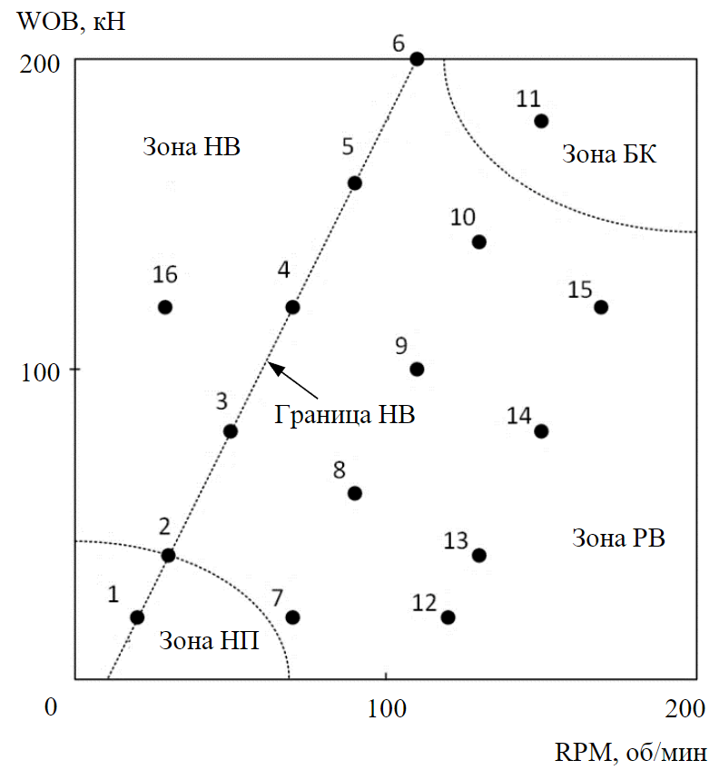
Fig.4. Rotary drilling modes NUR – non-uniform rotation of the bit; UR – uniform rotation of the bit; IP – insufficient parameters; LT – lateral torsion
One of the main tasks in drilling operations is the analysis of drilling modes in the coordinates (WOB×RPM) [32-35]. The first six modes refer to modes of unstable bit rotation and, as shown in Fig.4, in the coordinates (WOB×RPM) separating the zone of bit uniform rotation from the zone of non-uniform rotation with long stops. In the considered modes, a low level of mechanical drilling speed is noted, which is explained by the large diameter of the bit and the rather high energy intensity of class VII rock (accepted 750 kW·h/m3). For a bit with a diameter of 0.128 m, when drilling rocks of II-III energy intensity classes, the mechanical drilling speed reaches several tens of meters per hour. The given values of the bit depth are quite large, in the literature, you can find lower values of the depth limit, but the calculation is carried out per the rotation of the engine rotor, rather than the bit, the ratio of which is determined by the gear ratio.
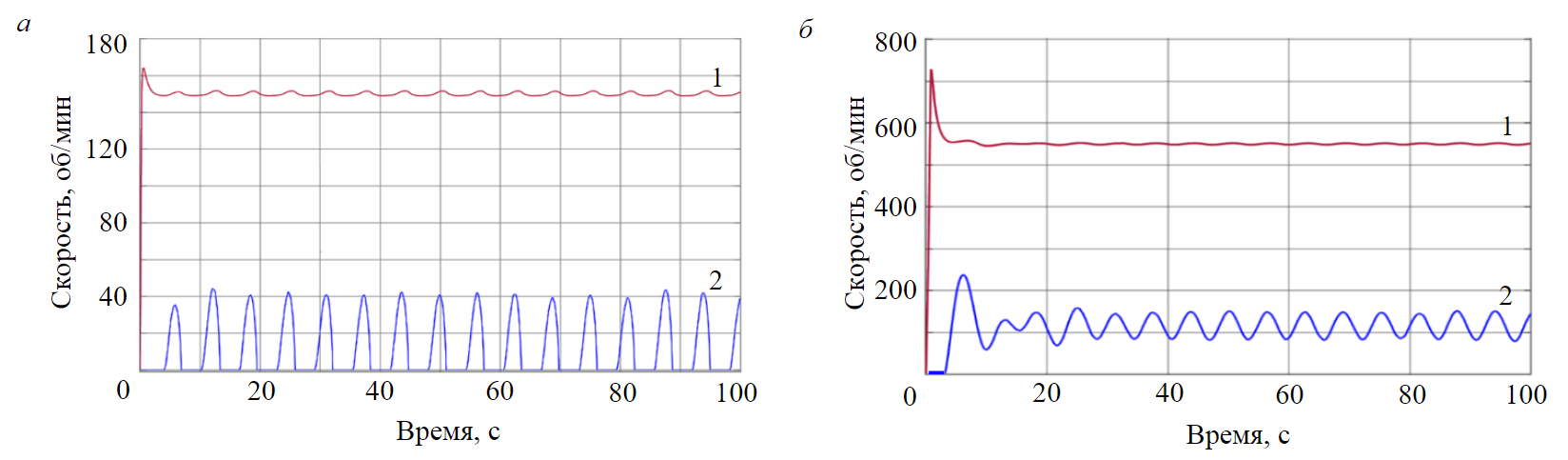
Fig.5. Rotor (1) and bit (2) speed curves in mode 16 of non-uniform bit rotation with long stops (a) and in mode 9 of uniform rotation (b)
Based on the analysis of the modes (1-15), it can be concluded that according to the energy-technological characteristics it is difficult to single out the modes of non-uniform rotation (NUR) of the bit if they are close to the zone of uniform rotation (UR). So, according to all characteristics, modes 4 (on the border of zones) and 9 (inside the UR zone) are close. The further the NUR mode is from the UR zone, for example, mode 16, the easier it is to establish a clear decrease in ROP and an increase in energy costs. The bit and the drilling rig rotor speed curves for mode 16 are shown in Fig.5, a. For comparison, Figure 5, b shows bit and rotor speed graphs for the mode of bit uniform rotation at point 9, in which bit speed fluctuations are much smaller and there are no bit stops. It should be noted that in both cases, the drive motor was started without load, with the clutch between the motor and the drilling rig rotor disconnected, and with a smooth increase in the set speed. Long bit stops lead to a significant decrease in the average bit speed, which can explain the decrease in the ROP and increase in energy consumption when drilling in the NUR zone. In the process of drilling, wear of the bit occurs, which, according to equation (2), affects the moment of resistance of the bit, while the boundary of the zone of uneven rotation of the bit moves to the right, increasing the NUR zone area of the bit. On the other hand, the size of the zone of uneven rotation is also affected by the diameter of the bit, when it decreases, the boundary of the zone of uneven rotation of the bit shifts to the left, reducing the NUR zone area of the bit.
Along with the zones of uniform and non-uniform rotation of the bit, Figure 4 shows a zone of insufficient drilling parameters (insufficient parameters) [20], where drilling is inefficient due to low ROP. The UR zone can also be divided, in its upper part (mode 11) the mechanical drilling speed is maximum, but in this case, accelerated wear of the bit occurs and a mode of impacts of the string against the borehole wall occurs – lateral vibrations (backward whirl) [21].
In the unstable non-uniform rotation modes of the bit, as can be seen from Fig.5, a, there are stops of the bit lasting several seconds. In modes 1-6, at the border of non-universal rotation, the stops are minimal and increase as the operating point moves deeper into the NUR zone, reaching ten se-conds. When the figure is scaled up, it can be seen that at the stopping intervals, the process of changing the speed decays [9]. As shown in Fig.6, a, the speed “freezes” from small positive and negative initial values, tending to zero. There are high-frequency oscillations (up to 3000 Hz) – torsional vibration, which reduces the resource of the bit. The conversion of high-frequency velocity oscillations into accelerations made it possible to obtain a vibration curve in the units of measurement adopted in drilling – shocks. The calculated graph of the bit vibration, presented in Fig.6, b, confirms in practice the possibility of dangerous vibrations, reaching several tens of shocks [25, 34].
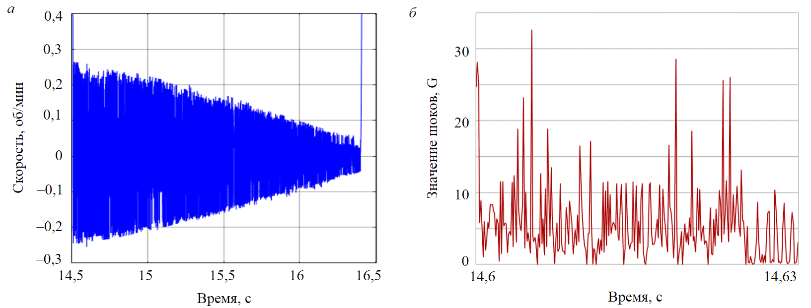
Fig.6. High-frequency oscillations (a) and vibration (b) of the bit when stopped and in stick-slip mode
It has been established that in the fading intervals, the bit is affected by positive and negative moments exceeding 80 kN·m, which correspond to the forces acting on the cutters (teeth) of the bit up to 15-20 kN, which is consistent with the critical force at which chipping of a reinforcing plate of the tooth can occur [26, 27]. In addition, the achieved value of the moment acting on the bit exceeds the recommended unscrewing force of the threaded connection of the bit. For a threaded connection up to 185.7 mm, it is 21.7 kN·m, which is much less than the moment values achieved on the bit. This confirms the possibility of accelerated wear and loss (unscrewing) of the bit and the inexpediency of the bit operation in stick-slip modes [27, 32]. Particularly rapid wear of the bit at high-frequency torsional vibrations is due to a change in the direction of bit rotation, in which the reaction force of the rock is directed not towards the bit teeth, but tangentially to them, causing chipping of the reinforcing plates of teeth and pulling out the teeth from the bit body sockets [33, 34]. Taking into account the design of PDC bits, it is more reasonable to model the frictional changes in the moment on the bit Tb(t) when the speed passes through zero using a model that differs from model (3) by an upward shift along the y-axis. A possible variant of such a model is presented in the work [35]. The calculations have shown that such a shift leads to an increase in the risk of a stick-slip effect.
Conclusion
A modification of the complex model of asynchronous electric drive of the rotor – drill string – bit – rock is proposed, which makes it possible to calculate and evaluate the selected drilling modes, taking into account their electromechanical, energy and technological efficiency [36-38] and dynamics of drilling processes [29, 30, 39]. Simulation results are consistent with rotary drilling practice [40-42]. The performed computer simulation of drilling modes confirmed the possibility of the stick-slip effect occurrence, accompanied by high-frequency vibrations during bit stops, during which it is possible to change the direction of rotation of the bit, its accelerated wear and unscrewing of the drilling tool. The model can be used as a base for further improvement of the control of the rotary [43-45] and other [46-48] drilling methods.
References
- Yunin E.K. Self-oscillations in deep drilling. Moscow: Librokom, 2013, p. 264 (in Russian).
- Guangjian Dong, Ping Chen. A Review of the Evaluation, Control, and Application Technologies for Drill String Vibrations and Shocks in Oil and Gas Well. Shock and Vibration. 2016. N 7418635, p. 34. DOI: 10.1155/2016/7418635
- Saldivar Márquez M.B., Boussaada I., Mounier H., Niculescu S.-I. Analysis and Control of Oilwell Drilling Vibrations. A Time-Delay Systems Approach. Springer International Publishing Switzerland, 2015, p. 282. DOI: 10.1007/978-3-319-15747-4
- Yang Liu, Wei Lin, Chávez J.P., De Sa R. Torsional stick-slip vibrations and multistability in drill-strings. Applied Mathematical Modelling. 2019. Vol. 76, p. 545-557. DOI: 10.1016/j.apm.2019.06.012
- Liping Tang, Xiaohua Zhu, Xudong Qian, Changshuai Shi. Effects of weight on bit on torsional stick-slip vibration of oil well drill string. Journal of Mechanical Science and Technology. 2017. Vol. 31. N 10, p. 4589-4597. DOI: 10.1007/s12206-017-0905-7
- Ershov M.S., Balitsky V.P., Melik-Shakhnazarova I.A. Rotary table DC drive operation under conditions of unstable rotation of drill bit. Mining Informational and Analytical Bulletin. 2020. N 11, p. 166-179 (in Russian). DOI: 10.25018/0236-1493-2020-11-0-166-179
- Ershov M.S., Komkov A.N., Feoktistov E.A. Operation of DC and AC drives of rotary table in unstable rotation mode of drill bit. Mining Informational and Analytical Bulletin. 2021. N 6, p. 153-167 (in Russian). DOI: 10.25018/0236_1493_2021_6_0_153
- Ershov M.S., Feoktistov E.A. Impact of unstable drilling on energy efficiency of drill rotor drive. Mining Informational and Analytical Bulletin. 2022. N 1, p. 148-161 (in Russian). DOI: 10.25018/0236_1493_2022_1_0_148
- Dardan Klimenta, Antti Hannukainen, Antero Arkkio. Estimating the parameters of induction motors in different operating regimes from a set of data containing the rotor cage temperature. Electrical Engineering. 2018. N 100, p. 139-150. DOI: 10.1007/s00202-016-0497-8
- Vaziri V., Oladunjoye I.O., Kapitaniak M. et al. Parametric analysis of a sliding-mode controller to suppress drill-string stick-slip vibration. Meccanica. 2020. N 55, p. 2475-2492. DOI: 10.1007/s11012-020-01264-5
- Dvoynikov M.V. Research on Technical and Technological Parameters of Inclined Drilling. Journal of Mining Institute. 2017. Vol. 223, p. 86-92. DOI: 10.18454/PMI.2017.1.86
- Dolgiy I.E., Nikolaev N.I. Resistance of rocks to crushing during well drilling. Journal of Mining Institute. 2016. Vol. 221, р. 655-660. DOI: 10.18454/PMI.2016.5.655
- Saldivar B., Mondié S., Ávila Vilchis J.C. The control of drilling vibrations: A coupled PDE-ODE modeling approach. International Journal of Applied Mathematics and Computer Science. 2016. Vol. 26. N 2, p. 335-349. DOI: 10.1515/amcs-2016-0024
- Pogorelov D.Yu., Lysikov N.N. Bit-rock interaction forces in computer-aided simulation of drillstring dynamics. Oil and Gas Business. 2019. N 3, p. 211-236 (in Russian).
- Koronatov V.A. Fundamentals of the mathematically rigorous theory of deep drilling. Systems. Methods. Technologies. 2020. N 2 (46), p. 23-29 (in Russian). DOI: 10.18324/2077-5415-2020-2-23-29
- Kunshin A., Dvoynikov M., Timashev E., Starikov V. Development of Monitoring and Forecasting Technology Energy Efficiency of Well Drilling Using Mechanical Specific Energy. Energies. 2022. Vol. 15 (19). DOI: 10.3390/en15197408
- Kadochnikov V.G., Dvoynikov M.V. Development of Technology for Hydromechanical Breakdown of Mud Plugs and Improvement of Well Cleaning by Controlled Buckling of the Drill String. Applied Sciences. 2022. Vol. 12 (13). DOI: 10.3390/app12136460
- Lukyanov E.E., Kudasheva S.V. Guidelines for the interpretation of mud logging data. Novosibirsk: Istoricheskoe nasledie Sibiri, 2016, p. 512 (in Russian).
- Vromen T.G.M., Dai C.H., Van de Wouw N. et al. Mitigation of torsional vibrations in drilling systems: a robust control approach. IEEE Transactions on Control Systems Technology. 2019. Vol. 27. Iss. 1. N 8094252, p. 249-265. DOI: 10.1109/TCST.2017.2762645
- Tengesdal N.K., Hovda S., Holden C. A Discussion on the Decoupling Assumption of Axial and Torsional Dynamics in Bit-rock Models. Journal of Petroleum Science and Engineering. 2021. Vol. 202. N 108070. DOI: 10.1016/j.petrol.2020.108070
- Amorim Jr. D.S., Santos O.L.A., Azevedo R.C. New industry standards to increase the reliability of drilling operations. Holos. 2019. Vol. 6, p. 1-14. DOI: 10.15628/Holos.2019.9009
- Neskoromnykh V.V., Popova M.S., Golovchenko A.E. et al. Method of drilling process control and experimental studies of resistance forces during bits drilling with PDC cutters. Journal of Mining Institute. 2020. Vol. 245, p. 539-546. DOI:10.31897/PMI.2020.5.5
- Neskoromnykh V.V., Chikhotkin A.V. Analysis of rock destruction mechanics by PDC cutters with regard to dynamic cutting–shearing processes and resistance. Mining Informational and Analytical Bulletin. 2020. N 4, p. 127-136 (in Russian). DOI: 10.25018/0236-1493-2020-4-0-127-136
- Neskoromnykh V.V., Popova M.S., Zotov Z.G., Liu Baochang. Algorithm of diamond drilling system control. Bulletin of the Tomsk Polytechnic University. Geo Аssets Engineering. 2022. Vol. 333. N 2, р. 81-89 (in Russian). DOI: 10.18799/24131830/2022/2/3562
- Abdul Rani A.M., Khairiyah I., Ab Adzis A.H. et al. Investigation on the effect of changing rotary speed and weight bit on PCD cutter wear. Journal of Petroleum Exploration and Production Technology. 2020. Vol. 10, p. 1063-1068. DOI: 10.1007/s13202-019-00795-2
- Tretyak A.А., Litkevich Yu.F., Borisov K.A. Influence of torsional and longitudinal vibrations on drilling speed and formation of breakdowns of cutting elements of PDC reinforced drill bits. Bulletin of the Tomsk Polytechnic University. Geo Аssets Engineering. 2019. Vol. 330. N 12, p. 135-141 (in Russian). DOI: 10.18799/24131830/2019/12/2410
- Borisov K.A., Tretyak A.A., Sidorova E.V. Impact of vibrations on strength properties of drill bits reinforced by PDC. Prospect and protection of mineral resources. 2019. N 12, p. 33-37 (in Russian).
- Tretyak A.Ya., Sidorova E.V., Litkevich Yu.F. et al. Drilling bit PDC plates lifetime control. Bulletin of the Tomsk Polytechnic University. Geo Аssets Engineering. 2021. Vol. 332. N 8, p. 28-35 (in Russian). DOI: 10.18799/24131830/2021/8/3302
- Litvinenko V.S., Dvoynikov M.V. Methodology for determining the parameters of drilling mode for directional straight sections of well using screw downhole motors. Journal of Mining Institute. 2020. Vol. 241, p. 105-112. DOI: 10.31897/PMI.2020.1.105
- Neskoromnykh V.V., Popova M.S. Development of a drilling process control technique based on a comprehensive analysis of the criteria. Journal of Mining Institute. 2019. Vol. 240, p. 701-710. DOI: 10.31897/PMI.2019.6.701
- Kozyaruk А.Е. Development experience and development prospect of electromechanical technological complexes of movement and positioning of technic shelf development equipment. Journal of Mining Institute. 2016. Vol. 221, p. 701-705. DOI: 10.18454/PMI.2016.5.701
- Zhiqiang Huang, Yachao Ma, Qin Li, Dou Xie. Geometry and force modeling, and mechanical properties study of polycrystalline diamond compact bit under wearing condition based on numerical analysis. Advances in Mechanical Engineering. 2017. Vol. 9 (6), p. 1-15. DOI: 10.1177/1687814017702080
- Guohui Zhang, Xiwen Zhang, Rong Chen et al. Pediction method of rock stratum anti-diamond characteristics of carbonate rocks used in Qinghai YingXi block. 2018 3rd International Conference on Advances in Energy and Environment Research (ICAEER 2018), September 2018, Guilin, China. E3S Web of Conferences. 2018. Vol. 53 (12). N 03002, p. 1-5. DOI: 10.1051/e3sconf/20185303002
- Zalyaev M.F. The exploration of vibration while drilling wells on termokarstovoe gas deposit. Oil and Gas Business. 2015. N 4. Vol. 13, p. 36-40 (in Russian).
- Leonov G.A., Kiseleva M.A. Stability of electromechanical models of drilling systems under discontinuous loads. Doklady Physics. 2012. Vol. 57. N 5, p. 206-209 (in Russian).
- Dvoynikov M.V., Nutskova M.V., Blinov P.A. Developments Made in the Field of Drilling Fluids by Saint Petersburg Mining University. International Journal of Engineering, Transactions A: Basics. 2020. Vol. 33. Iss. 4, p. 702-711. DOI: 10.5829/IJE.2020.33.04A.22
- Litvinenko V.S., Dvoynikov M.V. Monitoring and control of the drilling string and bottomhole motor work dynamics. Topical Issues of Rational use of Natural Resources. 2019. Vol. 2, p. 804-809. DOI: 10.1201/9781003014638-42
- Guanggjian Dong, Ping Chen. A Review of the Evaluation, Control, and Application Technologies for Drill String Vibrations and Shoks in Oil and Gas Well. Shock and Vibration. 2016. N 7418635, p. 34. DOI: 10.1155/2016/7418635
- Ritto T.G., Ghandchi-Tehrani M. Active control of stick-slip torsional vibrations in drill-strings. Journal of Vibration and Control. 2018. Vol. 25. Iss.1, p. 1-9. DOI: 10.1177/1077546318774240
- Pérez-Aracil J., Camacho-Gómez C., Pereira E. et al. Eliminating Stick-Slip Vibrations in Drill-Strings with a Dual-Loop Control Strategy Optimised by the CRO-SL Algorithm. Mathematics. 2021. Vol. 9. N 1526. DOI: 10.3390/math9131526
- Pavković D., Šprljan P., Cipek M., Krznar M. Cross-axis control system design for borehole drilling based on damping optimum criterion and utilization of proportional-integral controllers. Optimization and Engineering. 2021. Vol. 22, p. 51-81. DOI: 10.1007/s11081-020-09566-z
- Wei Lin, Paez Chavez J., Yang Liu et al. Stick-slip suppression and speed tuning for a drill-string system via proportional-derivative control. Applied Mathematical Modelling. 2020. Vol. 82, p. 487-502. DOI: 10.1016/j.apm.2020.01.055
- Vaziri V., Kapitaniak M., Wiercigroch M. Suppression of drill-string stick–slip vibration by sliding mode control: Numerical and experimental studies. European Journal of Applied Mathematics. 2018. Vol. 29. Iss. 5, p. 805-825. DOI: 10.1017/S0956792518000232
- Litvinenko V.S., Dvoinikov M.V. Justification of the Technological Parameters Choice for Well Drilling by Rotary Steerable Systems. Journal of Mining Institute. 2019. Vol. 235, p. 24-29. DOI: 10.31897/PMI.2019.1.24
- MacLean J.D.J., Vaziri V., Aphalec S.S., Wiercigrochd M. Feedback control method to suppress stick-slip in drill-strings featuring delay and actuation constraints. The European Physical Journal Special Topics. 2021. Vol. 230, p. 3627-3642. DOI: 10.1140/epjs/s11734-021-00228-4
- Simonyants S.L, Al Taee M. Stimulation of the Drilling Process with the Top Driven Screw Downhole Motor. Journal of Mining Institute. 2019. Vol. 238, p. 438-442. DOI: 10.31897/PMI.2019.4.438
- Dvoynikov M.V., Sidorkin D.I., Kunshin A.A., Kovalev D.A. Development of hydraulic turbodrills for deep well drilling. Applied Sciences (Switzerland). 2021. Vol. 11. Iss. 16. DOI: 10.3390/app11167517
- Dvoynikov M., Kunshin A., Blinov P., Morozov V. Development of Mathematical Model for Controlling Drilling Parameters with Screw Downhole Motor. International Journal of Engineering, Transactions A: Basics. 2020. Vol. 33. Iss.7, p. 1423-1430. DOI: 10.5829/IJE.2020.33.07A.30
- Podoliak A.V., Blinov P.A. The technology of directional drilling in ice via drills on carrying cable. International Journal of Applied Engineering Research. 2016. Vol. 11 (9), p. 6411-6417.