
Improving the efficiency of autonomous electrical complex with renewable energy sources by means of adaptive regulation of its operating modes
- 1 — Ph.D., Dr.Sci. Dean Saint Petersburg Mining University ▪ Orcid ▪ Elibrary ▪ Scopus
- 2 — Ph.D. Associate Professor Saint Petersburg Mining University ▪ Orcid ▪ Elibrary ▪ Scopus ▪ ResearcherID
- 3 — Postgraduate Student Saint Petersburg Mining University ▪ Orcid ▪ Elibrary ▪ Scopus ▪ ResearcherID
Abstract
Renewable energy sources are gradually becoming useful in mining industry. They are actively used in remote, sparsely populated areas to power shift settlements, geological and meteorological stations, pipeline equipment, mobile cell towers, helicopter pads lighting, etc. In comparison with diesel generators, systems with renewable sources do not require fuel transportation, have short payback periods and flexible configuration for different categories of electrical loads. The main obstacles to their spread are instability of generation and high cost of produced electricity. One of the possible ways to solve these problems is to develop new technologies, increase power density of generators and energy storage systems. The other way represents energy saving and rational use of affordable resources. The new solutions for implementation of the second method are proposed in this work. The object of the study is autonomous DC electrical complex with photovoltaic and wind power sources. In such systems the generated power from renewable sources is transferred to consumers via intermediate DC bus, the voltage level of which affects the power losses in the process of power transmission. The vast majority of complexes have a problem that their DC bus voltage is constant, while the optimum voltage level with lowest losses varies depending on the generated and consumed power. Therefore, electrical complexes potentially lose a part of the transmitted energy. To avoid this, a special algorithm was added to automatically adjust DC bus voltage to optimum level according to changes in working conditions. An additional contribution to efficiency improvement can be made by dynamic change of operating frequency in power converters depending on their load. The evaluation based on results of computer simulation showed that in a complex with rated power 10 kW active power losses during its lifetime can be reduced by 2-5 %.
None
Introduction
The global electrical industry is rapidly changing. Because of development of technologies, changes are not only quantitative, but also qualitative, irreversibly changing the principles of modern electrical systems. The key principles of such systems are decentralization, digitalization, and intellectualization of the processes of generation, distribution, and consumption of electrical energy.
New trends also have an impact on mining industry. The tasks of optimizing technological chains and increasing labor productivity come to the fore [1-3]. Thus the problem of providing electricity to remote and sparsely populated areas rich in deposits of natural resources is quite acute. The high cost of electricity there slows down the speed of development, forcing consumers to look for new power sources, as well as to form their own, more efficient small local power grids (microgrids) [4, 5].
Russia has a sustainable centralized power supply system, thus the use of autonomous microgrids with their own generation sources is justified only in the northern and northeastern regions [6-8]. In the past their inclusion in centralized power supply system was considered inefficient and too expensive. As a result, power supply in these territories was carried out from diesel generators with low efficiency and high cost of electricity generation, which reaches 80-120 rub./kW·h [9].
The use of renewable energy sources (RES) with a lifetime of 20-25 years can reduce the cost to 25-35 rub./kW·h [10]. The cost depends not only on money expenses, but also on the efficiency of energy conversion and transmission to the consumer. The purpose of this study is to propose a new approach to increase energy efficiency of autonomous microgrids with renewable energy sources. The relevance of the work is connected with the importance of the topic of energy saving for mining industry consumers placed in remote northern territories, which receive support of the Russian go-vernment.
Methods. The lifetime of microgrids with RES is more than 20 years. Money expenses include capital costs at the start of the project, annual maintenance costs, and disposal costs at the end of the project. The cost of electricity (COE) is equal to the ratio of total monetary expenses to the total consumed electricity. At the same time, the consumed electricity Wc is not equal to the generated Wgen due to the losses in the power system:
где η – efficiency of electrical energy transfer. The higher η, the lower the COE, in modern microgrids η = 0,8-0,85 [11].
For mining industry the use of renewable energy is most justified for powering small loads (1-10 kW) that are tens and hundreds of kilometers away from the main power transmission lines [12-14]. Such consumers are small shift settlements, geological and meteorological stations, mobile cell towers, pipeline equipment, engines of small pumps, corrosion protection systems, helicopter pads lighting systems, security or communication objects, leak detection equipment, etc.
Microgrids with RES may have variety of architectures and control principles. The system can be based on direct or alternating current [15], centralized or decentralized control principles [16], may work autonomously or exchange energy with another microgrids [17, 18]. The simplest autonomous microgrid with RES is shown in Fig.1, a. Coordination of RES and loads is carried out through intermediate DC bus with UDC voltage level. The battery (BAT) is directly connected to the bus. The battery charge is carried out with energy received from solar panels and wind turbines and converted by pulsed DC/DC and AC/DC converters. All converters work independently of each other.
However, when the battery is directly connected to DC bus, it leads to its faster obsolescence [19]. Pulse currents of random magnitude and shape from plenty of generators and power loads connected to DC bus shorten the battery life. Depending on the degree of battery obsolescence and its charge level, the bus voltage can vary greatly, which causes problems with stability of the system. Real practice shows that most of the failures of autonomous microgrids consist precisely in the failure of batteries [20]. At the same time, the cost of battery replacing can be up to 60 % of the cost of the entire system.
To extend the battery lifetime, it is connected to DC bus not directly, but through a bidirectional DC/DC converter that controls battery charge and discharge processes [21]. This converter maintains the stability of DC bus voltage level and controls the battery current. The use of centralized control (Fig.1, b) ensures coherent operation of all converters. The stable operation of the complex has a balance in generated Pgen and consumed Pload power, which, taking into account losses Ploss, can be written as:
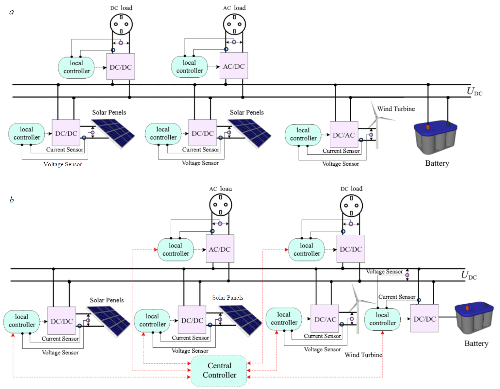
Fig.1. Microgrid with RES: battery is connected to DC bus directly (а), via bidirectional DC/DC converter (b)
All voltage converters connected with renewable energy sources operate in maximum power point tracking (MPPT) [22-24]. In this mode, their input resistance is regulated in such a way as to receive maximum power from RES [25, 26]. For example, operating point of a solar panel with a photovoltaic (PV) PPV output power (Fig.2, a) will be set to position A, and when the generated power changes, it will be automatically moved to position B (Fig.2, b).
Boost circuits are most often used as DC/DC converters with MPPT mode [27]. An increase of voltage is necessary since the output voltage of RES is usually small, especially during poor generation. The output voltage-ampere characteristic (VAC) of boost converter operating in MPPT mode is a hyperbola (Fig.2, c), the power at all points of which is the same (Fig.2, d). The maximum output current is limited at short-circuit current ISC of solar panel. The maximum output voltage is limited at level Ulim by inner overvoltage protection circuit. The output current of MPPT converter depends on the voltage level of DC bus UDC and inversely proportional to it
Considering by analogy the work of the other converters in microgrid, it is possible to identify general patterns. The principle of operation of bidirectional DC/DC battery charge-discharge converter is described in [28, 29], of inverter in [30, 31]. When microgrid operates, each converter has its own operating point. Since they are all connected to a common DC bus, the position of the points will be affected by the voltage level UDC.
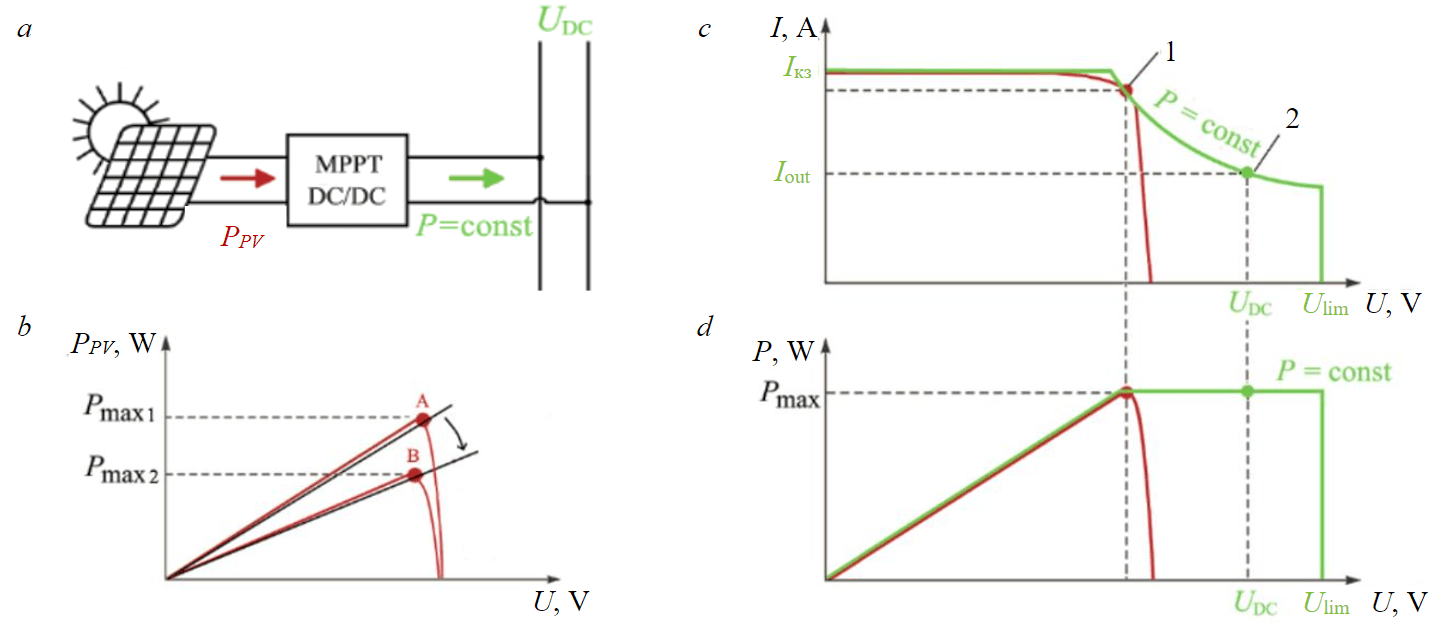
Fig.2. Operation of solar panel with boost DC/DC converter: а – scheme; b – MPPT mode; c – output VAC of the panel and converter; d – power characteristics of the panel and converter 1 – operating point of solar panel; 2 – of converter
The lower limit of permissible UDC values should be higher than the maximum output voltage generated by RES. The upper limit is limited by economic criterion – with an increase of UDC voltage, the electronic components of converters become more expensive. Works [32-34] are devoted to the choice of DC bus voltage. For household grids with rated power of up to 10 kW, the most common levels are 12, 24, and 48 V [35], for grids of greater power 380 and 400 V [36].
For the vast majority of microgrids DC bus voltage level is constant. When microgrid operates, voltage deviation is allowed within no more than ±10 % of the nominal value. At the same time, it was shown in [26, 37] that the optimum voltage, which will be characterized by the lowest losses during power transmission, varies depending on the volume of generation and consumption. As a result, microgrids with constant voltage level inevitably lose a part of the transmitted power.
The authors of [26, 37] have not shown how to implement automatic adjustment of DC bus voltage to the optimum, so this issue requires further exploration. As we already know, the efficiency of voltage converters in microgrid depends on the voltage level of DC bus UDC. Having a mathema-tical model of power losses in each converter, this dependence can be calculated. The power loss model for boost DC/DC converters was obtained in [38], for buck converters in [39], for inverter in [40, 41], for bidirectional battery charge-discharge converter in [42, 43].
The active power losses in pulse converters, if all necessary parameters of the circuit are known and the operating frequency of conversion is determined, can be reduced to a function of three variables
where Uin, Uout – input and output converter voltage; Iout – output converter current. For DC-converters, these variables characterize direct current. For AC-converters, these variables are rms values of phase currents and voltages.
Since all converters in microgrid are connected to DC bus, one of these three variables represents UDC voltage. The flow of reactive power in microgrid, thanks to the use of DC bus and pulse voltage converters, is actually reduced to zero. Therefore, calculations of reactive power are not considered in this research. The efficiency of all converters will be related to active power losses Ploss by formula
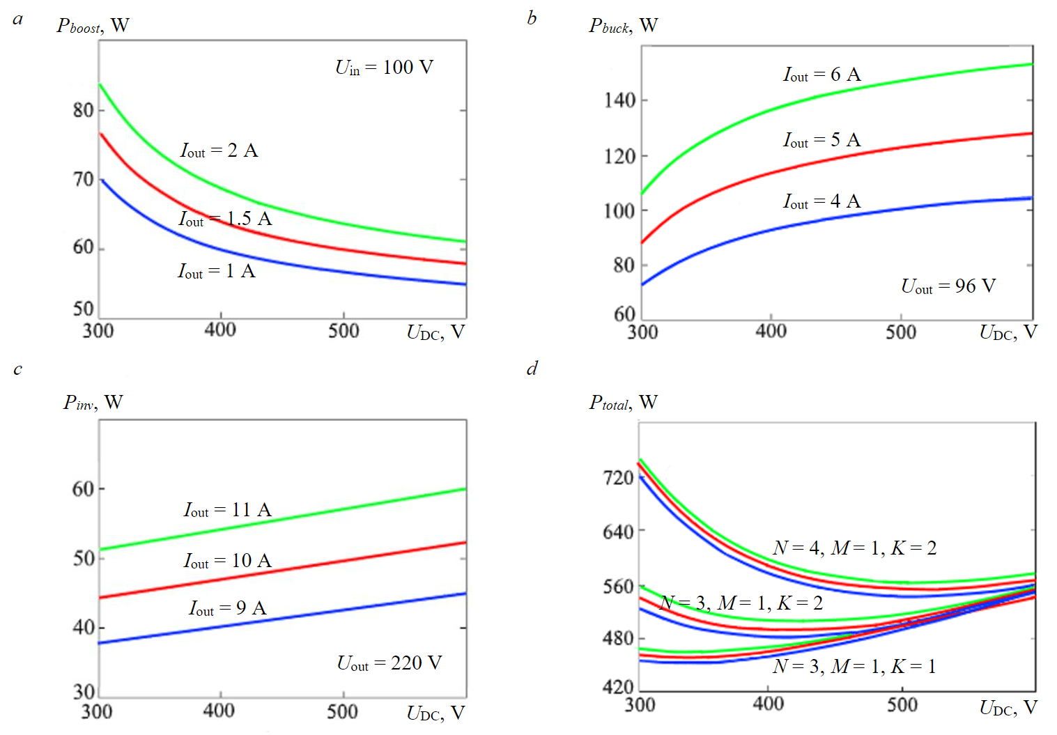
Fig.3. Graphs of the dependence of active power losses on DC bus voltage: a – for boost converter; b – for battery charge-discharge converter; c – for inverter; d – total losses in microgrid
On the basis of mathematical models of losses according to the formula (4), the dependences of Ploss on UDC bus voltage for boost converter, for battery charge-discharge converter, and for inverter were plotted (Fig.3, a-c). For plotting a microgrid with the total generated power of 4 kW was consi-dered. The output voltage of RES was set to 100 V DC, the battery voltage was 96 V, the output voltage of inverter was 220 V, and the DC bus voltage range was 310-600 V. The graphs of losses were plotted with three different loads on every converter, i.e. by setting three different values of their output current Iout. Total power losses of the entire system will be equal to the sum of the losses of the converters:
where N – number of operating boost converters; M – number of battery charge-discharge converter; K – number of inverters.
By summing up the loss graphs of all converters according to formula (6), the Ptotal(UDC) loss dependence graph of the entire complex was determined. Ptotal loss graphs (UDC) were plotted with different values of N, M, and K (Fig.3, d).
It can be seen from Fig.3, d that the point of minimum losses with different structure of microgrid and different converters load will be different. By adjusting the UDC voltage level of DC bus according to the minimum of losses during the microgrid operation, it is possible to increase the total energy efficiency.
In addition, power losses of the system can be reduced not only by varying the DC bus voltage, but also by changing the operating frequency of pulse converters depending on their load. Active power of the converter load
where E is the energy converted in one working cycle, J; fs is the operating frequency of the conversion, Hz.
The operating frequency affects the dynamic losses in switching semiconductor elements. The higher it is, the higher the losses. If load power changes, then at E = const. according to the formula (7), the operating frequency can also be changed. Thus, if the load decreases, the efficiency of the converter can be improved by reducing its operating frequency.
The proposed algorithm for adaptive adjustment of operating modes of microgrid, which increases its energy efficiency, is based on the assessment of active power losses in converters using their mathematical models.
To carry out calculations, a computing unit (CU) has been added to the complex, in which power loss models of all converters are stored (Fig.4, a). In addition, the array of possible values of DC bus voltage UDC is stored in CU memory, from which the best value is determined as a result of calculations.
Communication channels are established between local controllers (LC) of voltage converters and CU. Local controllers, using current and voltage sensors, measure the variables which are necessary for calculating power losses according to formulas (4) and (6). According to the measured value of current, the load on the converter is estimated by local controller and, according to formula (7), the operating frequency of the conversion is adjusted.
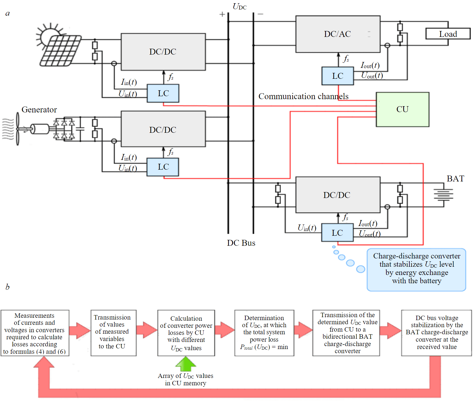
Fig.4. Microgrid with the search of the optimal mode of operation: а – scheme; b – algorithm for finding the optimal DC bus voltage level
Further, the measured values of variables are transmitted via communication channels to CU, which calculates converters power losses with different UDC bus voltage variants and selects the variant at which the total calculated losses Ptotal(UDC) of the system would be minimal. The found value is transmitted from CU to the LC of the battery charge-discharge converter, which stabilizes the UDC bus voltage at the received value. The block diagram of the algorithm is shown in Fig.4, b. To test the proposed idea, a simulation computer model of an autonomous microgrid with rated power of 10 kW in MatLab Simulink software package was created.
Simulational models of solar panel and battery were taken from [44]. The model of the wind generator is based on [45], where the operation of wind turbine with diode rectifier was considered. The authors have shown that if a filter capacitance is connected after the rectifier, then the voltage at the output of the rectifier at the maximum generated power point is associated with this power by the expression
где KV – constructive coefficient of proportionality, KV = 0.69 [45]; ρ – air density, ρ = 1.225 kg/m3; R – length of wind turbine blades; Cp – wind turbine power coefficient, depending on tip speed ratio λ and pitch angle θ, lying in range 0-0.6; Ud– voltage drop in diode rectifier.
At the same time, maximum power value taken from wind turbine depends on the wind speed v
The simulation computer model of the complex is shown in Fig.5. It comprises three arrays of solar panels and one wind turbine, which produces an already rectified DC voltage. Power loads are
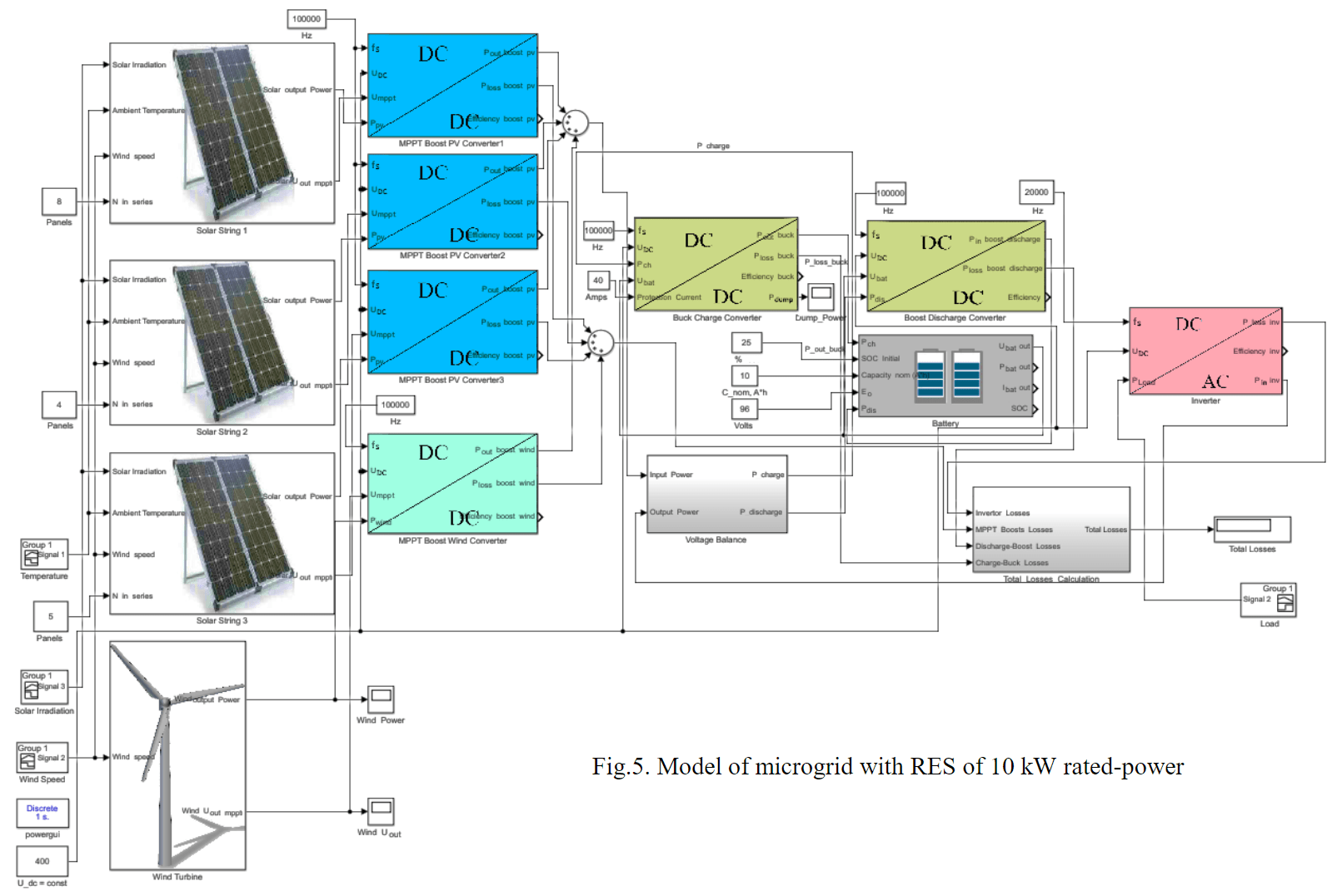
Fig.5. Model of microgrid with RES of 10 kW rated-power
simulated by Load unit powered by DC/AC voltage converter. The power taken from renewable sources is converted by pulsed DC/DC converters. The output power of these converters is summed up, as a result the total generated power is determined. After that, in Voltage Balance block, the power consumed by the loads is subtracted from the total generated power. If the difference turns out to be positive, it goes to the battery charge. If negative, it is replenished by discharging of battery. The bidirectional battery charge-discharge converter is represented by two DC/DC blocks: Buck Charge Converter – carrying out the charge, and Boost Charge Converter – carrying out the discharge. The parameters of RES and battery models are given in Table 1, the models of pulse voltage converters – in Table 2.
Table 1
Parameters of RES and battery
|
Solar panel |
Wind turbine |
Battery |
|
Nominal power 250 W |
Nominal power 7500 W |
Open circuit voltage 96 V |
|
Open circuit voltage 37.98 V |
Open circuit voltage 240 V |
Capacity 10 А∙h |
|
Short current 9.04 А |
Tip speed ratio λ = 7 |
Input resistance 0.0048 Ohm |
|
Voltage at maximum power point 30.63 V |
Length of wind turbine 1.6 m |
Permissible state of charge 20-100 % |
|
Current at maximum power point 8.79 А |
Permissible wind speed 3-14 m/s |
Initial charge 25 % |
Table 2
Parameters of pulsed converter models
|
Parameters |
DC/DC of solar panel |
DC/DC of wind turbine |
DC/DC of charge-discharge battery |
DC/AC |
|
Operating mode |
MPPT |
MPPT |
Stabilization of UDC |
Stabilization of voltage for loads |
|
Scheme |
Boost converter [22] |
Boost converter [43] |
Buck-boost converter [28] |
Full-bridge converter [30] |
|
Transistors |
||||
|
Type |
MOSFET |
MOSFET |
MOSFET |
IGBT |
|
Operating frequency |
100 kHz |
100 kHz |
100 kHz |
20 kHz |
|
Open channel resistance/voltage drop in open state |
0.002 Ohm |
0.002 Ohm |
0.002 Ohm |
1.8 V |
|
Average time of turn-on/turn-off |
30 ns |
30 ns |
30 ns |
42 ns |
|
Output capacity |
100 pF |
100 pF |
100 pF |
200 pF |
|
Gate threshold voltage |
12 V |
12 V |
12 V |
12 V |
|
Diodes |
||||
|
Voltage drop |
0.3 V |
0.3 V |
0.3 V |
1 V |
|
Dynamic resistance |
0.9 Ohm |
0.9 Ohm |
0.9 Ohm |
0.7 Ohm |
|
Reverse recovery time |
45 ns |
45 ns |
45 ns |
60 ns |
|
Inductor |
||||
|
Inductance |
70 uH |
50 uH |
50 uH |
30 uH |
|
Resistive load |
0.3 Ohm |
0.2 Ohm |
0.15 Ohm |
0.8 Ohm |
|
Electrolytic capacitors |
||||
|
ESR |
0.02 Ohm |
0.02 Ohm |
0.02 Ohm |
0.02 Ohm |
The input of the solar panel model receives the data about hourly intensity of solar radiation (Fig.6, a) and ambient temperature (Fig.6, b) throughout the year. The input of the wind turbine model receives the data about hourly wind speed (Fig.6, c). All of them are hourly average meanings taken from NASA meteorological database. Meteorological data from the north of Zabaikalskiy krai for 2022 were used for modeling.
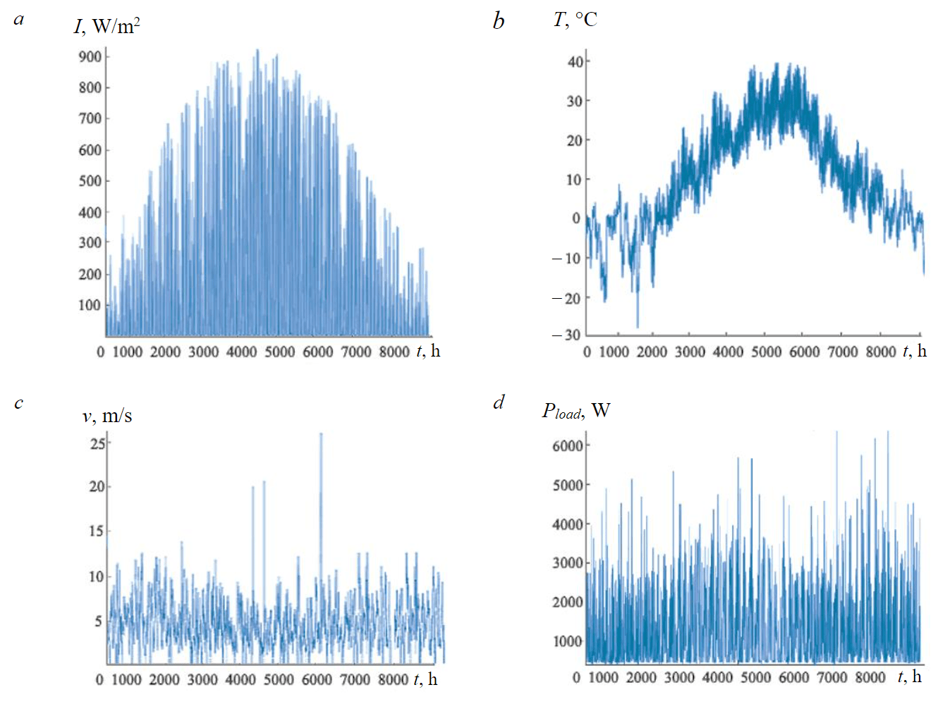
Fig.6. Data for modeling of microgrid: a – solar radiation intensity; b – ambient temperature; c – wind speed; d – hourly load consumption profile
Power taken from solar panels gets to DC/DC converters MPPT Boost PV Converter, which power losses model is based on formulas from [38]. The input data for the model represents operating frequency of conversion fs, DC bus voltage UDC, generated by solar panels voltage UMPPT and power PPV. The output data represents calculated power losses Ploss boost PV, output power Pout boost PV and efficiency of conversion Efficiency boost PV.
Power taken from wind turbine supplies DC/DC converter MPPT Boost Wind Сonverter, which power losses model is also based on [38]. The input data for this model represents generated by wind turbine power Pwind and voltage UMPPT, operating frequency fs and DC bus voltage UDC. The output data represents losses Ploss boost wind, output power Pout boost wind, and efficiency of conversion Efficiency boost wind.
The DC/AC converter power losses model is based on [40, 41]. The input of the model receives the data about operating frequency of conversion fs, hourly power consumption of the load Pload (Fig.6, d), voltage level of DC bus UDC. As a load a small shift settlement consisting of several residential structures was considered, where the main consumers are electrical appliances and lighting. The data about power consumption was taken from the LoadProfileGenerator*[1]database. The output data for the DC/AC converter model represents power losses Ploss inv, efficiency of conversion Efficiency and consumed from the DC bus power Pin inv.
The DC bus model is represented by Voltage Balance block. This block compares total generated power Input output and total consumptive power Output Power. If their difference turns out to be greater than zero, then this excess power Pch is directed to the battery charge, if less, then the lack of this power Pdis will be taken from the battery discharge.
Bidirectional DC/DC charge-discharge converter is represented by Buck Charge Converter and Boost Discharge Converter blocks. The model of converter in charge mode Buck Charge Converter is based on the works [39, 42]. This converter has a current protection circuit limiting the maximum charge current Protection Current. The input data for the model represents charge power Pch, DC bus voltage UDC, battery voltage Ubat, and operating frequency fs. The output data represents power losses Ploss buck, output power Pout buck, efficiency of conversion Efficiency buck, and excess power dissipated on ballast resistors Pdump.
The model of converter losses in battery discharge mode Boost Discharge Converter is based on [43]. The input data represents operating frequency fs, DC bus voltage UDC, battery voltage Ubat, and power Pdis injecting to DC bus. The output data represents power Pbat dis taken from the battery, power losses Ploss boost dis, and efficiency of conversion Efficiency.
The calculation of total microgrid power losses is carried out in Total Losses Calculation block. The input of the unit receives information about power losses of all converters, then these losses are summed up.
Results. During the process of computer simulation our microgrid operation was reproduced throughout the year including 8760 hours. The simulation results are shown in Fig.7. In order to represent the waveforms on enlarged scale, the time interval only from 2000 to 2600 hours is shown. The RES output waveforms (Fig.7, a) is represented by two graphs: generated power of solar panels PPV, generated power of wind turbine PWT. Pload is a waveform of load active power, state of charge (SOC) is a battery charging level.
The voltage UPV and current IPV waveforms generated by one array of solar panels are shown in Fig.7, b. The voltage UWT and current IWT waveforms of one wind turbine are shown in Fig.7, c. Battery voltage and charge-discharge current are shown in Fig.7, d. Efficiency of explored microgrid was assessed by measuring its total power losses Ptotal. Initially, these power losses were measured in case of constant DC bus voltage 400 V and constant operating frequency of converters: 100 kHz for DC/DC converters and 20 kHz for DC/AC converters. After that, power losses were adjusted to a minimum (for implementing Ptotal = min) by means of regulation of operating frequency fs of the convertors (Fig.7, e) and DC bus voltage UDC (Fig.7, f). The values of 370-600 V were used as DC bus voltage range. Operating frequency of DC/DC converters varied between 20-100 kHz depending on their load.
The waveform of total microgrid power losses Ptotal is shown in Fig.7, g. As a result of use of proposed technical solution, the microgrid losses were decreased. To quantify this decrease, Ptotal power losses were summed up over 8760 hours, as a result of which the total losses for the year were determined. The increase of microgrid efficiency for one year was calculated as follows:
where Ptotal1 represents total losses of active power for one year in case of constant DC bus voltage and operating frequency of all converters; Ptotal2 represents total losses of active power for one year in case of variable bus voltage and operating frequency of all converters.
The evaluation of Ptotal showed that the use of proposed technical solution made it possible to decrease power losses for one year by 2 % with varying bus voltage and by 5 % with variation of both DC bus voltage and operating frequency of all converters. Since power losses throughout the entire life are equal to the sum of losses of separate years, the reduction of losses over the entire life of the microgrid thanks to the use of our proposed solution can be also estimated at 2-5 %.
Discussion of the results
The efficiency increase of autonomous microgrid with RES was achieved thanks to the adaptive regulation of its operating modes. The proposed method is based on the use of mathematical models of converters power losses, therefore, a large amount of calculations is required for its implementation. Specifically for this purpose, a separate CU was added to microgrid, storing all mathematical models in its memory. This unit is connected to the converters by communication channels and continuously receives from them the values of variables necessary for calculations. There are the following features of the system functioning:
Fig.7. Microgrid modeling: а – total generated and consumed power; b – output voltage and current of one array of solar panels; c – output voltage and current of wind turbine; d – batery voltage and current; e – regulation of DC/DC converters frequency; f – DC bus voltage regulation; g – total microgrid power losses 1 – adaptive regulation of DC bus voltage and converters operating frequency; 2 – constant DC bus voltage and frequency
- Digital control of converters is required using microcontrollers (MC) or Field-Programmable Gate Arrays (FPGA). With the help of current and voltage sensors, they measure the variables necessary to calculate power losses and transmit them to CU via communication channels. Based on the measured current, the operating frequency of the conversion is adjusted.
- Computing unit is a digital unit which represents a computer or a separate board with its own MC or FPGA, the memory of which stores mathematical models of power losses of all converters.
- Efficiency encrease depends on the accuracy of mathematical models. For this reason, calibration of models with real converters is desirable during the microgrid development. All electrical circuits and parameters of electronic components inside power converters should be known in advance. It is possible to replace the elements only with full functional analogues.
- The speed of data exchange between CU and LC of converters must be consistent with the speed of calculations, i.e. CU should have time to perform calculations before it receives new values of currents and voltages of the converters.
- Due to the above features, it will not be possible to use any converters available on the market. The system requires purposeful development of converters, which, however, is not very complicated process.
The developed method of intelligent microgrid control makes it possible to increase the efficiency of autonomous microgrids with RES. The disadvantages of the proposed method include the need to use digital controllers and the need to add some more communication channels for data exchange between converters and CU, which leads to increase of microgrid total cost. In addition, the system will be characterized by low flexibility, since any change in its structure or component elements will lead to a discrepancy between mathematical models embedded in CU and the actual microgrid operation. In this case, you will need to make edits to the models.
Conclusion
The new time dictates new requirements. That is why mining industry in modern world should be technological, efficient, reliable, safe, constantly improving sector of the economy. In our country most of the natural resources are located in remote, sparsely populated areas where there is no readily accessible electricity. The use of fuel generators is associated with low environmental friendliness and high cost of electricity generation, which hinders the development and forces mining companies to bear high money expenses. The use of renewable energy is a modern technological solution that can give a “second life” to many objects of mining industry and stimulate the development of new projects.
Despite the solution of logistical and environmental problems, the instability of electricity ge-neration and the poor development of storage systems continue to be one of the main obstacles to the spread of autonomous microgrids with RES. One of the possible ways to solve these problems represents energy saving and rational use of affordable resources. A new solution was proposed to improve the efficiency of autonomous microgrid by adaptive regulation of its operating modes. The voltage level of intermediate DC bus and operating frequency of electric power converters in microgrid were considered as regulated parameters. In case of permanent changing of generated and consumed power typical for all power systems with RES, the optimum microgrid operating mode with least power losses also changes. In the course of the study, a new algorithm was developed for automatic regulation of microgrid operating modes, based on the use of mathematical models of converters power losses. The models make it possible, taking into account the volume of generated and consumed power, to calculate the optimal voltage level of the DC bus and the operating frequency of power converters for the current working conditions.
The results showed that in 10 kW microgrid the reduction of active power losses over the year was about 2 % with regulation of DC bus voltage only and about 5 % with regulation of bus voltage and operating frequency of power converters.
The direction of future research will be devoted to the efficiency estimation of hybrid microgrids with renewable energy sources and diesel generators.
* LoadProfileGenerator – modeling tool for residential energy consumption. URL: https://www.loadprofilegenerator.de (accessed 02.03.2023).
References
- Zhukovskiy Yu.L., Korolev N.A., Malkova Ya.M. Monitoring of grinding condition in drum mills based on resulting shaft torque. Journal of Mining Institute. 2022. Vol. 256, p. 686-700. DOI: 10.31897/PMI.2022.91
- Pryakhin E.I., Troshina E.Yu. Study of technological and operational features of high-temperature-resistant composite films for laser marking of parts made of ferrous alloys. Chernye metally. 2023. N 4, p. 74-80 (in Russian). DOI: 10.17580/chm.2023.04.12
- Sychev Yu.A., Kostin V.N., Serikov V.A., Aladin M.E. Nonsinusoidal modes in power-supply systems with nonlinear loads and capacitors in mining. Mining Informational and Analytical Bulletin. 2023. N 1, p. 159-179 (in Russian). DOI: 10.25018/0236_1493_2023_1_0_159
- Gerasimova I.G., Oblova I.S., Golovina E.I. The Demographic Factor Impact on the Economics of the Arctic Region. Resources. 2021. Vol. 10. Iss. 11. N 117. DOI: 10.3390/resources10110117
- Lavrik A., Zhukovskiy Yu., Tcvetkov P. Optimizing the Size of Autonomous Hybrid Microgrids with Regard to Load Shifting. Energies. 2022. Vol. 14. Iss. 16. N 5059. DOI: 10.3390/en14165059
- Samylovskaya E., Makhovikov A., Lutonin A. et al. Digital Technologies in Arctic Oil and Gas Resources Extraction: Global Trends and Russian Experience. Resources. 2022. Vol. 11. Iss. 3. N 29. DOI: 10.3390/resources11030029
- Khalturin A.A., Parfenchik K.D., Shpenst V.A. Features of Oil Spills Monitoring on the Water Surface by the Russian Fede-ration in the Arctic Region. Journal of Marine Science and Engineering. 2023. Vol. 11. Iss. 1. N 111. DOI: 10.3390/jmse11010111
- Kopteva A.V., Ushkova T.O. Development of methods for determining the relative weight of physical factors in pipeline paraffinization. E3S Web of Conferences. 2021. Vol. 266. N 04008. DOI: 10.1051/e3sconf/202126604008
- Zmieva K.A. Problems of energy supply in the Arctic regions. Russian Arctic. 2020. N 8, p. 5-14 (in Russian). DOI: 10.2441/2658-4255-2020-10086
- Lebedeva M.A. The state and prospects of renewable energy development in the regions of the Far North of Russia. Problems of Territory's Development. 2021. Vol. 25. N 4, p. 139-155 (in Russian). DOI: 10.15838/ptd.2021.4.114.8
- Hongwei Wu, Sechilariu M., Locment F. Influence of Dynamic Efficiency in the DC Microgrid Power Balance. Energies. 2017. Vol. 10. Iss. 10. N 1563. DOI: 10.3390/en10101563
- Martynov S.A., Masko O.N., Fedorov S.N. Innovative ore-thermal furnace control systems. Tsvetnye metally. 2022. N 4, p. 87-94 (in Russian). DOI: 10.17580/tsm.2022.04.11
- Romasheva N., Dmitrieva D. Energy Resources Exploitation in the Russian Arctic: Challenges and Prospects for the Sustainable Development of the Ecosystem. Energies. 2021. Vol. 14. Iss. 24. N 8300. DOI: 10.3390/en14248300
- Ilinova A., Solovyova V., Yudin S. Scenario-based forecasting of Russian Arctic energy shelf development. Energy Reports. 2020. Vol. 6. S. 9, p. 1349-1355. DOI: 10.1016/j.egyr.2020.11.022
- Dastgeer F., Gelani H.E. A Comparative analysis of system efficiency for AC and DC residential power distribution paradigms. Energy and Buildings. 2017. Vol. 138, p. 648-654. DOI: 10.1016/j.enbuild.2016.12.077
- Elistratov V.V. Renewable Energy Trends within the Concept of Low-Carbon Development. Applied Solar Energy. 2022. Vol. 58. Iss. 4, p. 594-599. DOI: 10.3103/S0003701X22040077
- Rizzato Lede A.M., Molina M.G., Martinez M., Mercado P.E. Microgrid Architectures for Distributed Generation: A Brief Review. IEEE PES Innovative Smart Grid Technologies Conference – Latin America (ISGT Latin America), 20-22 September 2017, Quito, Ecuador. IEEE, 2017. DOI: 10.1109/ISGT-LA.2017.8126746
- Abdallah W.J., Hashmi K., Faiz M.T. et al. A Novel Control Method for Active Power Sharing in Renewable-Energy-Based Micro Distribution Networks. Sustainability. 2023. Vol. 15. Iss. 2. N 1579. DOI: 10.3390/su15021579
- Kumar D., Zare F., Ghosh A. DC Microgrid Technology: System Architectures, AC Grid Interfaces, Grounding Schemes, Power Quality, Communication Networks, Applications, and Standardizations Aspects. IEEE Access. 2017. Vol. 5, p. 12230-12256. DOI: 10.1109/ACCESS.2017.2705914
- Aaron St. Leger. Demand response impacts on off-grid hybrid photovoltaic-diesel generator microgrids. AIMS Energy. 2015. Vol. 3. Iss. 3, p. 360-376. DOI: 10.3934/energy.2015.3.360
- Jiechao Lv, Xiaoli Wang, Guishuo Wang, Yuhou Song. Research on Control Strategy of Isolated DC Microgrid Based on SOC of Energy Storage System. Electronics. 2021. Vol. 10. Iss. 7. N 834. DOI: 10.3390/electronics10070834
- Ayop R., Chee Wei Tan. Design of boost converter based on maximum power point resistance for photovoltaic applications. Solar Energy. 2018. Vol. 160, p. 322-335. DOI: 10.1016/j.solener.2017.12.016
- Seguel J.L., Seleme Jr S.I., Moráis L.M.F. Comparison of the performance of MPPT methods applied in converters Buck and Buck-Boost for autonomous photovoltaic systems. Ingeniare. Revista chilena de ingeniería. 2021. Vol. 29. N 2, p. 229-244. DOI: 10.4067/S0718-33052021000200229
- Hanzaei S.H., Gorji S.A., Ektesabi M. A Scheme-Based Review of MPPT Techniques With Respect to Input Variables Including Solar Irradiance and PV Arrays’ Temperature. IEEE Access. 2020. Vol. 8, p. 182229-182239. DOI: 10.1109/ACCESS.2020.3028580
- Pande J., Nasikkar P., Kotecha K., Varadarajan V. A Review of Maximum Power Point Tracking Algorithms for Wind Energy Conversion Systems. Journal of Marine Science and Engineering. 2021. Vol. 9. Iss. 11. N 1187. DOI: 10.3390/jmse9111187
- Belsky A., Dobush V., Ivanchenko D. Wind-PV-Diesel Hybrid System with flexible DC-bus voltage level. Electric Power Quality and Supply Reliability Conference (PQ), 11-13 June 2014, Rakvere, Estonia. IEEE, 2014, p. 181-184. DOI: 10.1109/PQ.2014.6866806
- Honadia P.A.A., Barro F.I., Sané M. Performance Analysis of a Boost Converter with Components Losses. Energy and Power Engineering. 2018. Vol. 10. N 9, p. 399-413. DOI: 10.4236/epe.2018.109025
- Yuan-Chih Chang, Hao-Chin Chang, Chien-Yu Huang. Design and Implementation of the Battery Energy Storage System in DC Micro-Grid Systems. Energies. 2018. Vol. 11. Iss. 6. N 1566. DOI: 10.3390/en11061566
- Sayed Kh., Abo-Khalil A.G., Alghamdi A.S. Optimum Resilient Operation and Control DC Microgrid Based Electric Vehicles Charging Station Powered by Renewable Energy Sources. Energies. 2019. Vol. 12. Iss. 22. N 4240. DOI: 10.3390/en12224240
- Ternifi T.Z., Atik L., Bachir G. et al. Quality improvement of the AC electrical energy produced by a modular inverter dedicated to photovoltaic applications. AIP Conference Proceedings. Technologies and Materials for Renewable Energy, Environment and Sustainability (TMREES), 15-18 April 2016, Beirut, Lebanon. AIP Publishing, 2016. Vol. 1758. Iss. 1. N 030048. DOI: 10.1063/1.4959444
- Hannan S., Aslam S., Ghayur M. Design and real-time implementation of SPWM based inverter. International Conference on Engineering and Emerging Technologies (ICEET), 22-23 February 2018, Lahore, Pakistan. IEEE, 2018, p. 1-6. DOI: 10.1109/ICEET1.2018.8338637
- Castillo-Calzadilla T., Cuesta M.A., Olivares-Rodriguez C. et al. Is it feasible a massive deployment of low voltage direct current microgrids renewable-based? A technical and social sight. Renewable and Sustainable Energy Reviews. 2022. Vol. 161. N 112198. DOI: 10.1016/j.rser.2022.112198
- Habibi S., Rahimi R., Ferdowsi M., Shamsi P. DC Bus Voltage Selection for a Grid-Connected Low-Voltage DC Residential Nanogrid Using Real Data with Modified Load Profiles. Energies. 2021. Vol. 14. Iss. 21. N 7001. DOI: 10.3390/en14217001
- Siraj K., Khan H.A. DC distribution for residential power networks – A framework to analyze the impact of voltage levels on energy efficiency. Energy Reports. 2020. Vol. 6, p. 944-951. DOI: 10.1016/j.egyr.2020.04.018
- Lukutin B.V., Muravyev D.I. Prospects for decentralized DC systems with distributed solar generation. Bulletin of the Tomsk Polytechnic University. Geo Аssets Engineering. 2020. Vol. 331. N 6, p. 184-196 (in Russian). DOI: 10.18799/24131830/2020/6/2688
- Zhikang Shuai, Junbin Fang, Fenggen Ning, Z. John Shen. Hierarchical structure and bus voltage control of DC microgrid. Renewable and Sustainable Energy Reviews. 2018. Vol. 82. Part 3, p. 3670-3682. DOI: 10.1016/j.rser.2017.10.096
- Elvira D.G., Blaví H.V., Pastor À.C., Salamero L.M. Efficiency Optimization of a Variable Bus Voltage DC Microgrid. Energies. 2018. Vol. 11. Iss. 11. N 3090. DOI: 10.3390/en11113090
- Eichhorn T. Boost Converter Efficiency Through Accurate Calculations. Power Electronics Technology. 2008. Iss. 9, p. 30-35.
- Das N., Kazimierczuk M.K. Power losses and efficiency of buck PWM DC-DC power converter. Proceedings Electrical Insulation Conference and Electrical Manufacturing Expo, 23-26 October 2005, Indianapolis, USA. IEEE, 2005, p. 417-423. DOI: 10.1109/EEIC.2005.1566330
- Balıkcı A., Azizoğlu B.T., Durbaba E., Akpınar E. Efficiency Calculation of Inverter for PV Applications Using MATLAB and SPICE. International Conference on Optimization of Electrical and Electronic Equipment (OPTIM) & 2017 Intl Aegean Conference on Electrical Machines and Power Electronics (ACEMP), 25-27 May 2017, Brasov, Romania. IEEE, 2017, p. 593-598. DOI: 10.1109/OPTIM.2017.7975033
- Geetha K., Sreenivasappa B.V. Power Loss Calculation for IGBT and SiC MOSFET. Journal of Xi'an University of Architecture & Technology. 2020. Vol. XII. Iss. VIII, p. 378-382. DOI: 10.37896/JXAT12.08/2637
- Zheliazkov Y. Researching the efficiency of buck converter synchronous rectifier. Technology Audit and Production Reserves. 2020. Vol. 4. N 1(54), p. 44-50. DOI: 10.15587/2706-5448.2020.207893
- Hinov N., Arnaudov D., Valchev V., Vuchev S. Comparative Loss Analysis of Boost and Synchronous Boost DC-DC Converters. XXVI International Scientific Conference Electronics (ET), 13-15 September 2017, Sozopol, Bulgaria. IEEE, 2017. DOI: 10.1109/ET.2017.8124347
- Obukhov S.G., Plotnikov I.A. et al. Simulation model of operation of autonomous photovoltaic plant under actual operating conditions. Bulletin of the Tomsk Polytechnic University. Geo Аssets Engineering. 2017. Vol. 328. N 6, p. 38-51 (in Russian).
- Flores D.R.L., Gómez J.A.P., Herrera R.S., Alvarado M.S. Tracking Control of the Maximum Power Point (MPPT) in a Small Wind Turbine (SWT) for Isolated Residential Applications. WSEAS Transactions on Circuits and Systems. 2013. Vol. 12. Iss. 8, p. 253-261.