
Determination of the grid impedance in power consumption modes with harmonics
- 1 — Ph.D. Saint Petersburg Mining University ▪ Orcid
- 2 — Ph.D. Saint Petersburg Mining University ▪ Orcid
- 3 — Ph.D. Universiti Teknikal Malaysia Melaka ▪ Orcid

Abstract
The paper investigates the harmonic impedance determination of the power supply system of a mining enterprise. This parameter is important when calculating modes with voltage distortions, since the determined parameters of harmonic currents and voltages significantly depend on its value, which allow the most accurate modeling of processes in the presence of distortions in voltage and current. The power supply system of subsurface mining is considered, which is characterized by a significant branching of the electrical network and the presence of powerful nonlinear loads leading to a decrease in the power quality at a production site. The modernization of the mining process, the integration of automated electrical drive systems, renewable energy sources, energy-saving technologies lead to an increase in the energy efficiency of production, but also to a decrease in the power quality, in particular, to an increase in the level of voltage harmonics. The problem of determining the grid harmonic impedance is solved in order to improve the quality of design and operation of power supply systems for mining enterprises, taking into account the peculiarities of their workload in the extraction of solid minerals by underground method. The paper considers the possibility of determining the grid impedance based on the measurement of non-characteristic harmonics generated by a special nonlinear load. A thyristor power controller based on phase regulation of the output voltage is considered as such a load. Simulation computer modeling and experimental studies on a laboratory test bench are used to confirm the proposed method. The recommendations for selecting load parameters and measuring device connection nodes have been developed.
None
Correction to “Determination of the grid impedance in power consumption modes with harmonics” published 25.12.2024 in Volume 270, URL: pmi.spmi.ru/pmi/article/view/16630
These errors do not affect the conclusions of the article. The correction has been to the html and pdf versions of the article.
Introduction
The development of mining and processing technologies is characterized by an increase in energy consumption and in process automation. New technologies of electrothermal metallurgy are being introduced [1-3], renewable energy technologies are used to supply remote power plants in the oil and gas industry [4-6] and for autonomous power supply using hybrid plants [7, 8]. New technological installations are based on the use of power electronics devices, which are part of various semiconductor converters. This leads to harmonic currents injection into power supply system. The negative effects of voltage and current distortion are known and widely reported [9-11].
Underground mining power supply systems have such features as a high length of power lines and a dispersal of high power electrical installations [12-14]. This circumstance is one of the main reasons for the increase in voltage distortion levels, which depend on the equivalent impedance of the power supply system and on the harmonic currents. When modernizing energy-intensive installations in mining, such as drainage systems, fans, electric hoisting installations, etc., the automated converter technology is used [15-17]. Such installations increase the energy efficiency of the technological process, but they are sources of voltage and current distortions. The possibility of modeling such drives is studied in more detail in the works [18-20]. Predicting the voltage distortion levels, when modeling processes in an electrical grid in the presence of harmonics, is an important and urgent challenge for a design engineer or researcher. The paper [18] confirms the importance of taking into account the power quality indicators when calculating electrical loads and choosing the parameters of the main equipment at mining enterprises.
The impedance of the power supply system is widely used in the calculation of the electrical grid operating modes, including non-sinusoidal conditions [21-23]. It was shown in [23] that, depending on the measured values of the system impedance, it is possible to determine the dominant harmonic source at the point of common coupling of consumers. One of the features of underground mining power supply systems is the remoteness of electrical loads from the power source, and hence the high impedance value of the system. As a result, the levels of voltage distortion can significantly exceed the requirements of regulations. The efficiency of harmonic distortion compensation devices, such as passive harmonic filters, directly depends on the impedance of the supply system. Therefore, when choosing the parameters of such devices, it is necessary to know the value of the harmonic system impedance. The impedance of the power supply system can help in determining the harmonic source, i.e. settle disputes between the supplier of electrical energy and the consumer [24-26].
The harmonic system impedance can be determined by calculation or by measurement. The determination of the harmonic impedance using calculations is based on the assumption of its inductive nature and linear dependence on frequency:
where n – harmonic order; – inductive impedance at the fundamental frequency.
This method is simple and does not require the use of additional equipment. However, when modeling the operating modes of the power system, the accuracy of determining the harmonic levels decreases. This is due to the fact that the energy system impedance includes resistive and capacitive components, and has a nonlinear character [27, 28]. The application of an analytical method for estimating system impedance for wind turbines is shown in the work [29]. Also, the impedance of the power supply system can change over time, i.e. it can be non-stationary due to the connection of various additional loads upstream of the point of common coupling [30, 31]. On the other hand, the application of the measuring method is more laborious, but gives more accurate results [32, 33].
Measuring methods can be invasive and non-invasive. Invasive methods are based on the use of harmonic current generators, non-invasive methods are based on the measurement of harmonic currents and voltages for two consecutive times. A comparison of various methods for determining the system impedance is given in the article [34]. Using the method based on harmonic generators requires additional expensive equipment, as well as preliminary measurement of current harmonics in the power supply system in order to generate a special signal that excludes the existing ones. The method of two consecutive measurements is easier to apply. However, its principle is based on changing the parameters of nonlinear loads from the grid side or from the consumer side relative to the point of common coupling. It does not allow accurate measurement of the grid harmonic impedance in the condition of simultaneous changes in the load parameters from the grid side and from the consumer side. Error estimation of the system impedance measurement method based on load fluctuations is given in [35].
Another problem when investigating the impedance of an underground mining power supply system is that the loads can be highly variable at many connection points, and the harmonic system impedance can also be a non-stationary value. Approaches to determining harmonic system impedance in real time are described in [36, 37].
This paper proposes a method for measuring the harmonic system impedance based on connecting an additional nonlinear load with a certain range of harmonics, which does not require large implementation costs. However, nonlinear loads may have significant internal impedance in their composition, which may depend on frequency, thus being comparable in magnitude to the harmonic system impedance. Therefore, it is necessary to study the influence of the internal impedance of an additionally connected nonlinear load, the parameters of its power consumption and operating modes.
Methods
To determine the harmonic system impedance by the method under consideration, it is necessary to use a nonlinear electrical load that satisfies two conditions. Firstly, the nonlinear load should generate harmonic currents that are uncharacteristic for the power supply system. Non-characteristic harmonics of the nonlinear load are understood as harmonics that are absent or extremely small in the voltage spectrum when this nonlinear load is not connected. Secondly, this nonlinear load should have no internal harmonic impedance. So, it can be represented in the equivalent circuit as a set of parallel-connected current sources without additional impedances. The presence of internal impedance in the nonlinear load also distorts the value of the harmonic system impedance, since the internal impedance in the equivalent circuit is connected in parallel with the system impedance and therefore the calculated value of the system impedance is less than its real value. These conditions should be observed in order to accurately determine the harmonic system impedance. For example, in the equivalent circuit, the presence of voltage harmonics of the same frequency as the current harmonic of an additionally connected nonlinear load leads to an error in calculating the harmonic system impedance, because it is necessary to take into account the influence of this voltage source on the calculation.
Let us consider a simplified power supply scheme for underground mining associated with the extraction of solid minerals (Fig.1).
The power supply of underground consumers depends on many factors: the depth of the developed horizons, the voltage of underground electrical system, the overall load and type of power receivers, the method of mining, etc. However, all this is associated with an increase in the length of the distribution feeders and the dispersal of power receivers. The majority of mining machines and mechanisms are driven by asynchronous motors with a squirrel-cage rotor. Variable electrical drives are widely used in the mining and developing areas of coal mines. Often, six-pulse semiconductor frequency converters are used to control the rotation speed of motors. For energy-intensive customers where speed control is not required (main ventilation fans, compressors), synchronous motors are widely used. Recently, even for energy-intensive hoists, high-power frequency-controlled asynchronous motors are increasingly being used, which leads to problems in the field of power quality in terms of harmonics. Applications are found for soft starters made according to the scheme of thyristor voltage regulators, in particular, for conveyor installations. It should be noted that there are developments and tools that allow minimizing the influence of semiconductor converters of individual installations on the power supply system (active rectifier, input power active and passive filters). The high cost of such devices is one of the main reasons for the low rate of their implementation.
Thus, from the point of view of the goal set, it is possible to highlight the main positions. In underground mining power supply systems, there is a nonlinear load with the harmonics order n = 6k±1, where k = 1, 2, 3, …; that is characteristic for sixpulse rectifiers. In the current spectrum there are also even harmonics, which are characterized by a short duration of presence in starting modes of electrical equipment. The power supply system is an extensive radial grid and a sharply variable load at different points of connection to the grid.
As a nonlinear load that is necessary to determine the harmonic impedance of the power supply system, a specialized semiconductor device that generates uncharacteristic for an external power supply system harmonic currents can be used. It should be loaded with linear resistive elements, the parameters of which do not depend on frequency. According to the results of the experiments, it was revealed that such loads are, for example, a thyristor power controller (TPC) and an uncontrolled rectifier without a capacitive DC filter [38]. The uncontrolled rectifier has a spectrum that includes harmonics 6k±1, which can often be found in the external power supply grid. The TPC current consumption spectrum contains even harmonics, which in most cases are absent in the external grid. Therefore, TPC was chosen as the generator of uncharacteristic harmonics. This choice has some disadvantages. Firstly, TPC creates other harmonics in addition to uncharacteristic ones, including the current at the fundamental frequency, the value of which in all modes is greater than other harmonics. Secondly, to increase the accuracy of the measurement results, it is necessary to increase the TPC load power, therefore, the overall dimensions of the installation also increase.
Thus, to measure the harmonic system impedance, it is necessary to:
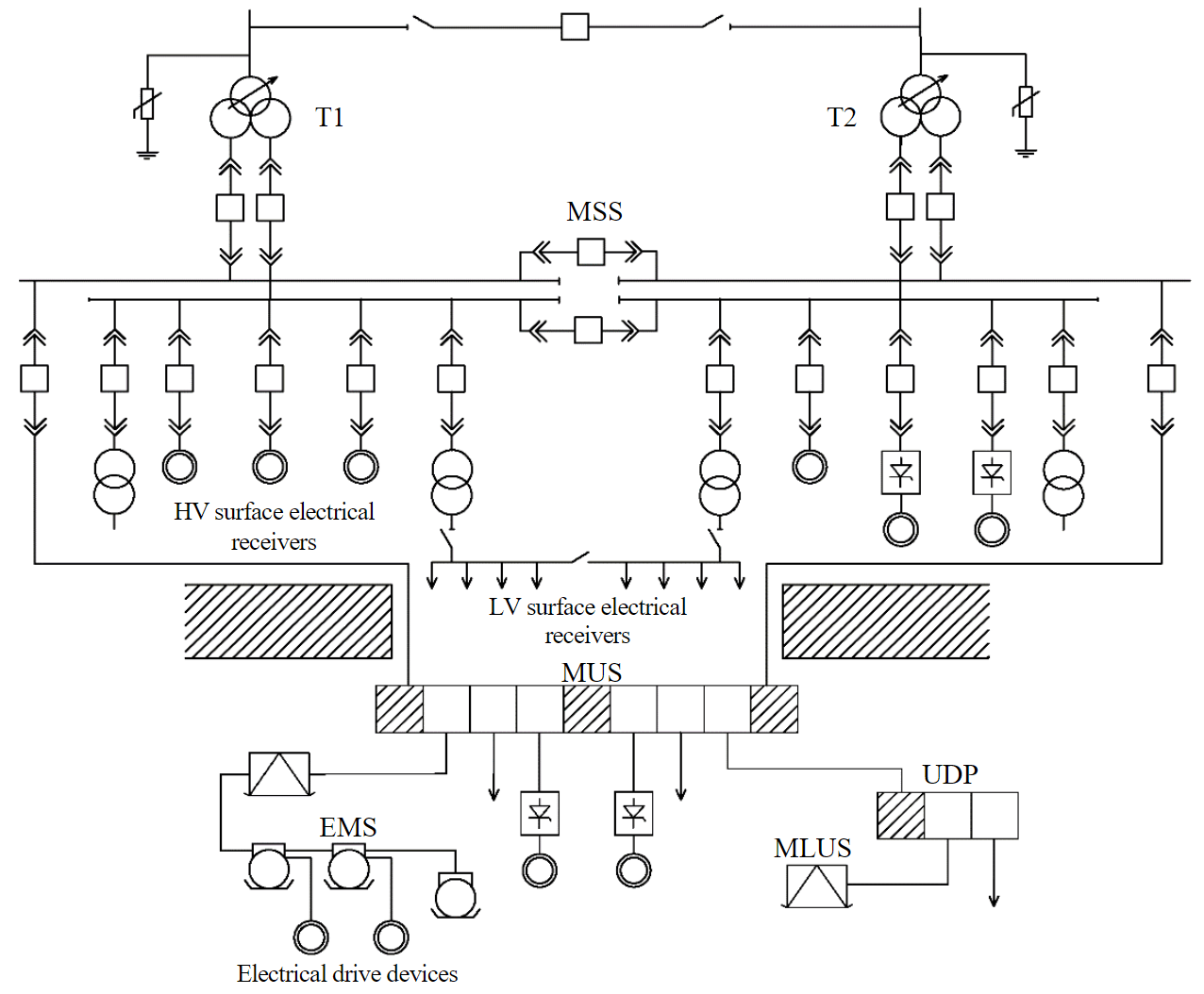
Fig.1. Simplified power supply scheme for mining production MSS – main step-down substation; MUS – main underground substation; T – power transformers; HV – high voltage; LV – low voltage; UDP – underground distribution point; MLUS – mobile local underground substation; EMS – explosion-proof mine starters
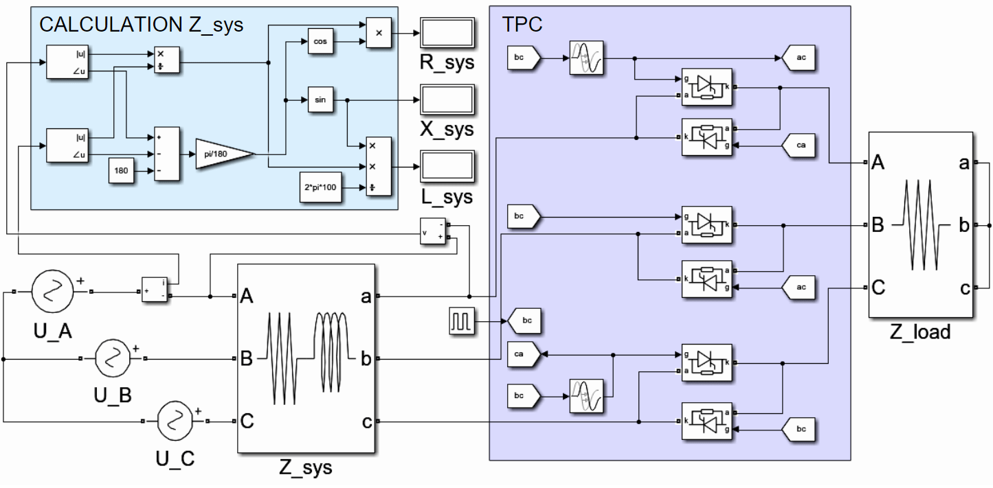
Fig.2. Simulation model in Matlab/Simulink
- Make sure that there are no uncharacteristic voltage harmonics in the supply grid when the uncharacteristic harmonics generator is turned off. If there are devices that generate even harmonics, they should be turned off. This is possible due to the small number of such devices in subsurface mining power supply systems. In the case of a short-term activation of such devices (for example, in the starting modes of engines), preliminary measurements can be carried out without turning them off with the control of such periods of switching on engines.
- Turn on the generator of uncharacteristic harmonics. Devices generating even harmonics can also be included in the work. In this case, it is necessary to take into account the location of such a load during measurements.
- Measure current and voltage waveforms at the connection point of the harmonic generator.
- Obtain the current and voltage spectrum at the input of the generator.
- Calculate the system impedance at uncharacteristic harmonics.
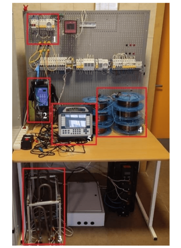
Fig.3. Laboratory test bench
To verify the proposed method for calculating the harmonic system impedance, a simulation model was created in the Matlab/Simulink (Fig.2). The simulation model consists of a three-phase symmetrical source (sources of sinusoidal voltage U_A, U_B, U_C), a thyristor power controller with a control system (TPC unit), thyristor regulator loads (Z_load unit), a system impedance (Z_sys unit) and a measurement and calculation of the system impedance unit (CALCULATION Z_sys). The TPC unit consists of three pairs of an inverse-parallel thyristors and operates in the phase regulation mode of the output voltage. CALCULATION Z_sys unit performs the calculations of the harmonic system impedance based on phase voltage and TPC current waveforms. The developed model was used to determine the harmonic system impedance with different value and type of the system impedance.
The verification of the computer model was carried out on a laboratory test bench (Fig.3), which consists of a three-phase symmetric voltage source (1), a TPC (2), loads in the form of electrical heating tubes (3), three induction coils (4) and voltage and current meter (5). As a registration device, an oscilloscope Rigol 1202 and a power quality analyzer Resource PQA were used. The obtained waveforms were processed in Matlab.
The parameters of the TPC and the system impedance are shown in the Table. All parameters of the model are identical to the parameters of the laboratory bench, and the algorithm for the TPC model operation is fully consistent with the operation of the real device.
Laboratory equipment parameters
|
Name of equipment |
Parameters |
|
System impedance |
|
|
Stage 1 |
R = 0.45 Ω; L = 1 mH |
|
Stage 2 |
R = 1.12 Ω; L = 4.1 mH |
|
Stage 3 |
R = 1.84 Ω; L = 8.8 mH |
|
Load of thyristor controller |
R = 96 Ω |
|
Thyristor power controller |
Irated = 30 A |
|
Three-phase supply grid |
Urated = 380 V; f = 50 Hz |
|
Short circuit power |
|
|
Stage 1 |
263 kVA |
|
Stage 2 |
85 kVA |
|
Stage 3 |
44 kVA |
|
System resistance |
10 Ω |
|
System capacitance |
2350 μF |
Induction coils have three stages of regulation, its parameters are shown in the Table. The magnitude-frequency characteristic of inductance is linear, which has been confirmed using a laboratory source of a variable frequency from 0 to 500 Hz. As an assumption, it is accepted that the impedance of 10 kV grid and above is not taken into account, since its value is much smaller than laboratory linear inductance.
The system impedance can have a complex dependence on the frequency and consist of different types of impedances. Experiments with various types of the system impedance, which depend on the frequency differently, have been conducted. In addition, a test of the proposed method on these types of impedance has been carried out.
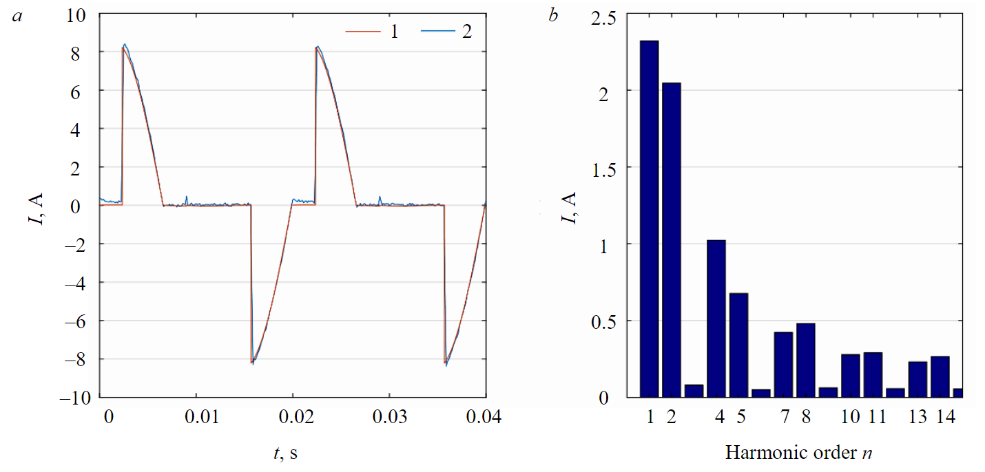
Fig.4. Waveform (a) and current spectrum (b) of TPC
Discussions
The simulation model in Matlab/Simulink has been verified using laboratory equipment with various TPC loading (from 0 to 50 %). TPC waveforms obtained during modeling and as a result of measurement on a laboratory test bench have been compared. This is confirmed by the waveforms presented in Fig.4. In Fig.4, a a comparison of waveforms obtained by modeling (1) and by an experiment on equipment (2) is presented. In Fig.4, b a spectrum of TPC current is presented.
The computer model under consideration has fully confirmed its performance for all even harmonics, i.e. the active and reactive impedance of the system have been determined. The error in determining the harmonic system impedance was less than 1 %. Thus, it is confirmed that equivalent circuit for uncharacteristic harmonics consists only of harmonic current sources and the system impedance. Therefore, the nth harmonic vector voltage of the system can be found according to the equation:
where – the nth harmonic vector voltage; – the nth harmonic vector current.
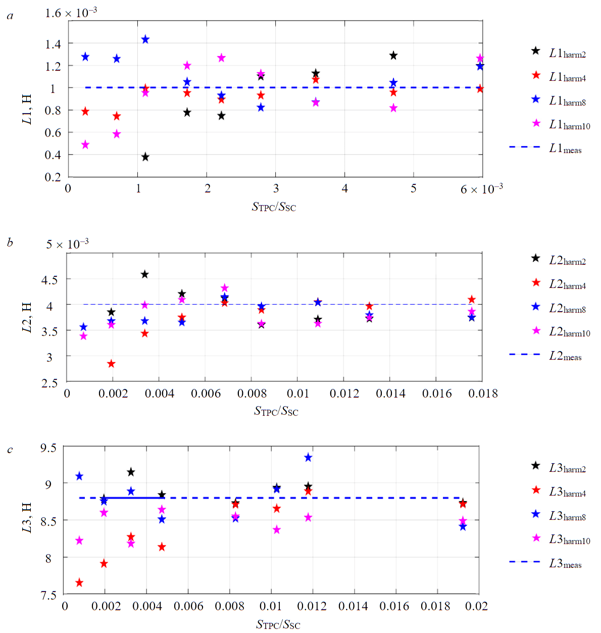
Fig.5. Calculated coil inductance values L1 (a), L2 (b), L3 (c) for harmonics 2, 4, 8, 10 and different power of TPC
To verify the proposed method, an experiment on a laboratory stand has been conducted. The TPC has worked in the phase control mode and its load has changed from 0 to 50 %. With a 100 % load, current distortions are zero and the load operates in a completely sinusoidal mode, so this mode is not considered. Figure 5 presents the calculated values of the L1, L2, L3 coils inductance for the 2nd, 4th, 8th and 10th harmonics with various TPC load. An important parameter when determining the harmonic system impedance using the proposed method is the short circuit power. This is due to the fact that with various harmonic currents, the corresponding voltage drop in the harmonic system impedance occurs, which may be within the meter error. In order to achieve the required values of harmonic currents and voltages, it is necessary to determine the range of corresponding TPC power values depending on the short circuit power of the system when performing calculations.
The characteristics presented in Fig.5 reflect the values of the calculated inductance for the 2nd, 4th, 8th and 10th harmonics depending on the TPC power and the short circuit power at the connection point of receivers. The dotted line shows the value of the inductance measured using a programmable laboratory source. The ratio of TPC power to short circuit power can serve as a criterion for selecting the TPC power that is suitable for the grid under study. Based on the dependencies obtained, the following conclusions can be drawn:
- TPC operating modes with minimum load (5-15 %) can be attributed to outliers, since in this case the values of the second harmonic of current and voltage are insignificant and the inductance calculation has a large error. The rest of the TPC operating modes are suitable for measuring and calculating inductance and have negligible error;
- taking into account the other modes of TPC operation (20-50 %), the average deviation from the measured value of the inductance is less than 5 %;
- the TPC harmonic equivalent circuit can be represented as parallel-connected current sources without internal impedance;
- when a TPC power value is 0.2 % of the short circuit power then the inductance of the power system is determined with the required accuracy.
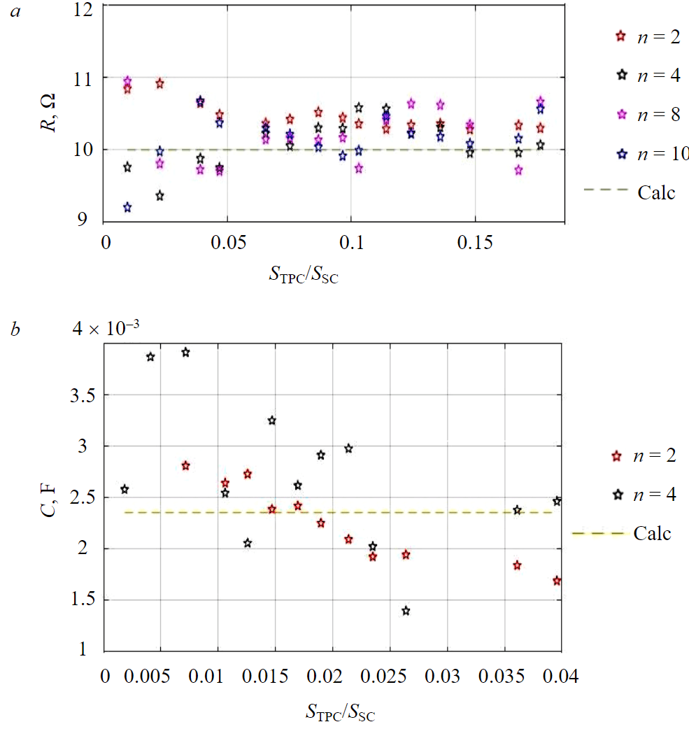
Fig.6. Measured impedance values with active (a) and capacitive (b) character
Further, experiments have been carried out for the active and capacitive system impedances in order to verify the previously obtained conclusions for these types of impedances. The measurement results for active and capacitive impedances are presented in Fig.6.
According to the experiment data, the measurement of the active impedance takes place with an error of less than 10 % in comparison with value of the real resistance (Fig.6, a). Moreover, when loading TPC in the range of 25-45 %, the measurement error does not exceed 5 %. The measurement error of the active system resistance is practically independent of the harmonic number. Resistance was measured in the range of 1-18 % of the short-circuit power, i.e. the TPC was one of the dominant loads. Figure 6, b shows the dependence of the calculated system capacity at different frequencies on the ratio of the TPC power to the short circuit power of the system. Using the described method, the system capacitance can only be determined with an error of 50 % at low-frequency harmonics, which can be explained as follows. Firstly, the TPC power does not exceed 4 % of the grid short-circuit power in laboratory conditions due to the low system impedance. Secondly, the capacitance becomes even smaller at higher frequencies, so it is not possible to reliably measure currents and voltages at these harmonics and calculate the system capacitance on their basis in laboratory conditions.
In most cases, for subsurface mining power supply systems, the impedance of the power system is active-inductive, especially for medium and low voltage grids. Therefore, the proposed method can be implemented without significant increases in the power of an additionally connected nonlinear load. The methodology for applying the developed method for determining the power supply system impedance of the subsurface mining consists of the following steps:
1. The analysis of the underground mining power supply system for the presence of uncharacteristic harmonics in the supply voltage is carried out on the basis of preliminary measurements of power quality indicators with the uncharacteristic harmonic generator turned off. An analysis of the types of power semiconductor converters in production is also carried out. If there are semiconductor converters that generate uncharacteristic even harmonics, they should also be turned off for the duration of the measurements. In the case of a short switching on of such devices (for example, in the starting modes of engines), preliminary measurements are possible without turning them off, with control and exclusion of such periods from the measured data. In the absence of uncharacteristic harmonics in the supply voltage, the transition to the next step is carried out. The presence of uncharacteristic harmonics in the supply voltage leads to an additional error in the calculation of the harmonic system impedance. This error was not evaluated in this work.
2. The selection of TPC power is determined based on the short circuit power at the investigated point of connection:
When measuring in a low-voltage electrical grid of a mining enterprise, which is characterized by the worst indicators in terms of distortion in comparison with grids of medium and high voltage class, the TPC power will be an insignificant value from ones to tens of kilowatts.
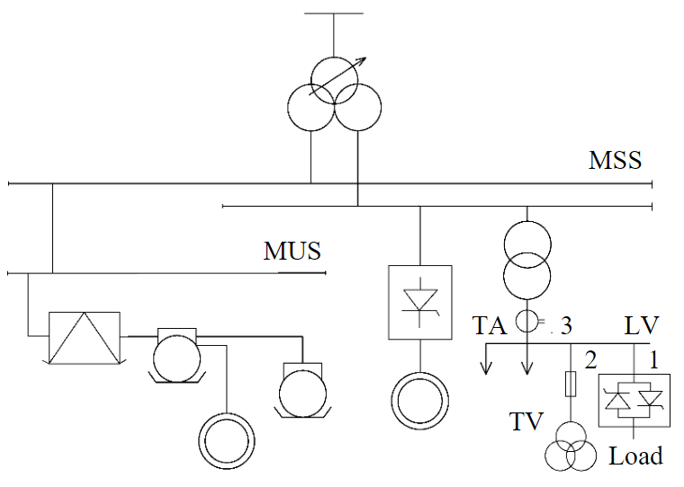
Fig.7. Simplified electrical single-line scheme TA – current transformer; TV – voltage transformer
3. Selection of connection points for measuring devices. The section of the grid (substation) is determined where it is necessary to solve the required problem. Namely, it is the calculation of distortion levels at the connection point of new nonlinear consumers, at the connection point of consumers when the load parameters and reactive power compensation devices change, at the connection point of consumers when installing harmonic reduction devices, etc. Figure 7 shows a simplified single-line electrical diagram, which considers the connection of the TPC and measurement circuits to the selected section of the grid.
If the power quality standards are exceeded and it is necessary to select the parameters of harmonic reduction devices, for example, on the buses of a low-voltage (LV) substation, it is necessary to determine the harmonic grid impedance at this node. The TPC connection is carried out on the LV substation buses (point 1), the measurement of the harmonic phase voltage is also carried out on the LV buses (point 2). The presence of internal impedance of such a nonlinear load can be minimized by correctly connecting the current measuring circuits. In this case, the measurement of harmonic currents is carried out at the input feeder of the substation (point 3). This choice of connection points for measuring circuits also applies to other voltage levels.
If there are additional devices on the LV substation buses that generate the same spectrum of non-characteristic harmonics, the same connection of the measuring current circuits on the input feeder is necessary. The presence of such devices only increases the uncharacteristic harmonic currents flowing through the impedance of the upstream grid. Consequently, the uncharacteristic harmonic voltages at this point and the accuracy of calculating the harmonic system impedance increase. If the enterprise has devices in the HV grid that also generate a spectrum of non-characteristic harmonics, it is necessary to connect measuring devices at such a substation (for example, main step-down substation). Then based on the measurements, the harmonic system impedance from the bus of main step-down substation is determined. At the LV substation, the harmonic system impedance will differ only by the parameters of the supply line from LV to the main step-down substation.
4 .Calculation of the harmonic system impedance based on the measured data of non-characteristic harmonic currents and voltages.
Conclusion
The conducted studies confirm the possibility of measuring the harmonic impedance of the system based on determining the response to uncharacteristic current harmonics generated using the proposed device in the form of a TPC. The use of such a device as a source of non-characteristic harmonics can be implemented to determine the system impedance at harmonic frequencies, which is confirmed by studies on physical and mathematical models in the absence of non-characteristic harmonics in the supply voltage. The TPC is a simpler and cheaper device than expensive harmonic generators.
The ratio of the short circuit power of the grid to the TPC power connected at the same node should be used as a selection criterion for the TPC power to determine the harmonic impedance of the system. Based on the analysis of short circuit power values in underground mining power supply systems, it was found that the TPC power will be from units to tens of kilowatts, depending on its connection node location. A technique for applying the proposed method to underground mining power supply systems is presented, which contains a preliminary analysis of the network and load, the selection of the required TPC parameters and the places for connecting the measuring circuits of current and voltage in the presence and absence of additional devices that generate a spectrum of characteristic and non-characteristic harmonics in the internal power supply system of the enterprise.
There are several directions for further research. First, thyristor controller improvement to amplify only non-characteristic harmonics and reduce the current magnitude at the fundamental frequency. Second, an assessment of the influence of uncharacteristic harmonics generated from the grid side. Third, the application of the proposed method for field measurements in order to measure the harmonic system impedance and develop a methodology for processing the measured data.
References
- Baake E., Shpenst V.A. Recent scientific research on electrothermal metallurgical processes. Journal of Mining Institute. 2019. Vol. 240, p. 660-668. DOI: 10.31897/PMI.2019.6.660
- Shklyarskiy Ya.E., Shklyarskiy A.Ya., Zamyatin Е.О. Analysis of distortion-related electric power losses in aluminum industry. Tsvetnye metally. 2019. N 4, p. 84-91 (in Russian). DOI: 10.17580/tsm.2019.04.11
- Khalifa A.A., Bazhin V.Yu., Ustinova Ya.V., Shalabi M.E.Kh. Study of the kinetics of the process of producing pellets from red mud in a hydrogen flow. Journal of Mining Institute. 2022. Vol. 254, p. 261-270. DOI: 10.31897/PMI.2022.18
- Kroposki B., Johnson B., Yingchen Zhang et al. Achieving a 100% Renewable Grid: Operating Electric Power Systems with Extremely High Levels of Variable Renewable Energy. IEEE Power and Energy Magazine. 2017. Vol. 15. Iss. 2, p. 61-73. DOI: 10.1109/MPE.2016.2637122
- Nikulin A.N., Epifancev K.V., Kovshov S.V., Korshunov G.I. The research of possibility to use the machine for biofuel production as a mobile device for poultry farm waste recycling. Life Science Journal. 2014. Vol. 11. N 4, p. 464-467.
- Zhukovskiy Y.L., Vasilev B.Y., Korolev N.A., Malkova Y.M. Analysis of the behavior of asynchronous electric drive with a closed scalar control system when changing the inductance of the magnetizing circuit. Indonesian Journal of Science and Technology. 2022. Vol. 8. N 1, p. 65-78. DOI: 10.17509/ijost.v8i1.51983
- Morenov V., Leusheva E., Lavrik A. et al. Gas-Fueled Binary Energy System with Low-Boiling Working Fluid for Enhanced Power Generation. Energies. 2022. Vol. 15. Iss. 7, p. 1-15. DOI: 10.3390/en15072551
- Shklyarskiy Y.E., Guerra D.D., Iakovleva E.V., Rassõlkin A. The influence of solar energy on the development of the mining industry in the Republic of Cuba. Journal of Mining Institute. 2021. Vol. 249, p. 427-440. DOI: 10.31897/PMI.2021.3.12
- Benaouadj M., Boumous Z., Boumous S. Active Harmonic Filtering for Improving Power Quality of an Electrical Network. Journal Européen des Systèmes Automatisés. 2022. Vol. 55. N 3, p. 397-403. DOI: 10.18280/jesa.550312
- Ruuskanen V., Koponen J., Kosonen A. et al. Power quality and reactive power of water electrolyzers supplied with thyristor converters. Journal of Power Sources. 2020. Vol. 459. N 228075. DOI: 10.1016/j.jpowsour.2020.228075
- Zhukovskiy Y., Tsvetkov P., Buldysko A. et al. Scenario Modeling of Sustainable Development of Energy Supply in the Arctic. Resources. 2021. Vol. 10. Iss. 12. № 124. DOI: 10.3390/resources10120124
- Belsky A.A., Morenov V.A., Kupavykh K.S., Sandyga M.S. Wind Turbine Electrical Energy Supply System for Oil Well Heating. Energetika. Proceedings of CIS higher education institutions and power engineering associations. 2019. Vol. 62. N 2, p. 146-154 (in Russian). DOI: 10.21122/1029-7448-2019-62-2-146-154
- Alexandrov V.I., Kopteva A.V., Serzan S.L. Effective Parameters of Tail Processing of Gold-Bearing Ore Hydrotransport for Verninskaya Processing Factory. Key Engineering Materials. 2020. Vol. 836, p. 25-35. DOI: 10.4028/www.scientific.net/KEM.836.25
- Abdallah W.J., Hashmi K., Faiz M.T., Flah A., Channumsin S., Mohamed M.A., Ustinov D.A. A Novel Control Method for Active Power Sharing in Renewable-Energy-Based Micro Distribution Networks. Sustainability. 2023. Vol. 15. N 1579. DOI: 10.3390/su15021579
- Munoz-Guijosa J.M., Kryltcov S.B., Solovev S.V. Application of an Active Rectifier Used to Mitigate Currents Distortion in 6-10 kV Distribution Grids. Journal of Mining Institute. 2019. Vol. 236, p. 229-238. DOI: 10.31897/PMI.2019.2.229
- Abramovich B.N., Ustinov D.A., Abdallah W.J. Modified proportional integral controller for single ended primary inductance converter. International Journal of Power Electronics and Drive Systems. 2022. Vol. 13. N 2, p. 1007-1025. DOI: 10.11591/ijpeds.v13.i2.pp1007-1025
- Raj L.R.L.V., Jidin A., Abdul Karim K. et al. Improved torque control performance of direct torque control for 5-phase induction machine. International Journal of Power Electronics and Drive Systems. 2013. Vol. 3. N 4, p. 391-399. DOI: 10.11591/ijpeds.v3i4.5249
- Lingom P.M., Song-Manguelle J., Doumbia M.L. et al. Electrical Submersible Pumps: A System Modeling Approach for Power Quality Analysis with Variable Frequency Drives. IEEE Transactions on Power Electronics. 2022. Vol. 37. Iss. 6, p. 7039-7054. DOI: 10.1109/TPEL.2021.3133758
- Yerbayev Y., Artyukhov I., Zemtsov A. et al. Negative Impact Mitigation on the Power Supply System of a Fans Group with Frequency-Variable Drive. Energies. 2022. Vol. 15. Iss. 23. N 8858. DOI: 10.3390/en15238858
- Jopri M.H., Abdullah A.R., Manap M. et al. An Improved Of Multiple Harmonic Sources Identification In Distribution System With Inverter Loads By Using Spectrogram. International Journal of Power Electronics and Drive Systems. 2016. Vol. 7. N 4, p. 1355-1365. DOI: 10.11591/ijpeds.v7.i4.pp1355-1365
- Shawon M.H., Barczentewicz S.H., Bień A., Hanzelka Z. Localization of Harmonic Sources in Power System – Simulation and Laboratory Study. Renewable Energy and Power Quality Journal. 2016. N 14, p. 546-551. DOI: 10.24084/repqj14.388
- Martinez R., Castro P., Arroyo A. et al. Techniques to Locate the Origin of Power Quality Disturbances in a Power System: A Review. Sustainability. 2022. Vol. 14. Iss. 12. N 7428. DOI: 10.3390/su14127428
- Srikanth P., Koley C. Deep learning and signal processing based algorithm for autorecognition of harmonic loads. Journal of Intelligent and Fuzzy Systems. 2022. Vol. 42. N 2, p. 1171-1184. DOI: 10.3233/JIFS-189780
- Kasemuana S.M., De Beer A.S., Pretorius J.H.C. A Practical Method to Identify Contributions of Harmonics in Power Systems: Method and Application. International Review of Electrical Engineering. 2021. Vol. 16. N 4, p. 304-315. DOI: 10.15866/iree.v16i4.19194
- Mokoena B., Eboule P.S.P., Pretorius J.H.C. Medium voltage consumers’ cost evaluation connected to a micro-grid PV system. Energy Reports. 2022. Vol. 8. S. 10, p. 235-244. DOI: 10.1016/j.egyr.2022.05.105
- Jopri M.H., Abdullah A.R., Sutikno T. et al. A Diagnostic Analytics of Harmonic Source Signature Recognition by Using Periodogram. International Journal of Electrical and Computer Engineering. 2018. Vol. 8. N 6, p. 5399-5408. DOI: 10.11591/ijece.v8i6.pp5399-5408
- Ebadi M., Bayat M., Asadi H. Evaluating maximum permissible feeder current in capacitive compensated harmonic polluted networks introducing Apparent RMS Current Ratio Index (ACRI). Electric Power Systems Research. 2020. Vol. 187. N 106511. DOI: 10.1016/j.epsr.2020.106511
- Yaqiong Li, Zhanfeng Deng, Tongxun Wang et al. Coupled Harmonic Admittance Identification Based on Least Square Estimation. Energies. 2018. Vol. 11. Iss. 10. N 2600. DOI: 10.3390/en11102600
- Xia Zhou, Yishi Liu, Ping Chang et al. Voltage Stability Analysis of a Power System with Wind Power Based on the Thevenin Equivalent Analytical Method. Electronics. 2022. Vol. 11. Iss. 11. N 1758. DOI: 10.3390/electronics11111758
- Ahmed E.F., Said E.-S.S.A., Abdel Mageed H.M., Ammar A.A. A novel interactive technique for load current harmonic reduction for any randomly utilized household equipment. International Journal of Power Electronics and Drive Systems. 2022. Vol. 13. N 4, p. 2159-2171. DOI: 10.11591/ijpeds.v13.i4.pp2159-2171
- Azebaze Mboving C.S., Hanzelka Z., Firlit A. Analysis of the Factors Having an Influence on the LC Passive Harmonic Filter Work Efficiency. Energies. 2022. Vol. 15. Iss. 5. N 1894. DOI: 10.3390/en15051894
- Singh R.S., Ćuk V., Cobben S. Measurement-Based Distribution Grid Harmonic Impedance Models and Their Uncertainties. Energies. 2020. Vol. 13. Iss. 16. N 4259. DOI: 10.3390/en13164259
- Wanjun Lei, Cheng Nie, Mingfeng Chen et al. A Fast-Transient Repetitive Control Strategy for Programmable Harmonic Current Source. Journal of Power Electronics. 2017. Vol. 17. Iss. 1, p. 172-180. DOI: 10.6113/JPE.2017.17.1.172
- Kanálik M., Margitová A., Bena L., Kanáliková A. Power System Impedance Estimation Using a Fast Voltage and Current Changes Measurements. Energies. 2021. Vol. 14. Iss. 1. N 63. DOI: 10.3390/en14010063
- Yang Wang, Wilsun Xu, Jing Yong. An Adaptive Threshold for Robust System Impedance Estimation. IEEE Transactions on Power Systems. 2019. Vol. 34. Iss. 5, p. 3951-3953. DOI: 10.1109/TPWRS.2019.2924349
- Sommer S., Aabrandt A., Jóhannsson H. Reduce-factor-solve for fast Thevenin impedance computation and network. IET Generation, Transmission & Distribution. 2019. Vol. 13. Iss. 2, p. 288-295. DOI: 10.1049/iet-gtd.2018.5330
- Ziteng Liu, Yonghai Xu, Haiwei Jiang, Shun Tao. Study on Harmonic Impedance Estimation and Harmonic Contribution Evaluation Index. IEEE Access. 2020. Vol. 8, p. 59114-59125. DOI: 10.1109/ACCESS.2020.2982950
- Skamyin A., Shklyarskiy Y., Dobush V., Dobush I. Experimental Determination of Parameters of Nonlinear Electrical Load. Energies. 2021. Vol. 14. Iss. 22. N 7762. DOI: 10.3390/en14227762