
Evaluation of the influence of the hydraulic fluid temperature on power loss of the mining hydraulic excavator
Abstract
In the steady state of operation, the temperature of a mining excavator hydraulic fluid is determined by the ambient temperature, hydraulic system design, and power losses. The amount of the hydraulic system power loss depends on the hydraulic fluid physical and thermodynamic properties and the degree of wear of the mining excavator hydraulic system working elements. The main causes of power losses are pressure losses in pipelines, valves and fittings, and leaks in pumps and hydraulic motors. With an increase in the temperature of hydraulic fluid, its viscosity decreases, which leads, on the one hand, to a decrease in power losses due to pressure losses in pipelines, valves and fittings, and, on the other hand, to an increase in volumetric leaks and associated power losses. To numerically determine the level of power losses occurring in the hydraulic system on an example of the Komatsu PC750-7 mining excavator when using Shell Tellus S2 V 22, 32, 46, 68 hydraulic oils with the corresponding kinematic viscosity of 22, 32, 46, 68 cSt at 40 °C, the developed calculation technique and software algorithm in the MatLab Simulink environment was used. The power loss coefficient, obtained by comparing power losses at the optimum temperature for a given hydraulic system in the conditions under consideration with the actual ones is proposed. The use of the coefficient will make it possible to reasonably select hydraulic fluids and set the values of the main pumps limit state and other hydraulic system elements, and evaluate the actual energy efficiency of the mining hydraulic excavator. Calculations have shown that the implementation of measures that ensure operation in the interval with a deviation of 10 % from the optimal temperature value for these conditions makes it possible to reduce energy losses from 3 to 12 %.
None
Introduction
It is well known that in most hydraulic systems, the efficiency does not exceed 75 %. In this case, the input power is spent on overcoming mechanical friction, pressure losses in pipelines, valves and fittings, and internal leakage of the hydraulic fluid. All power losses are converted into heat absorbed by the hydraulic fluid [1-3]. An increase in the temperature of the working fluid above a certain limit is accompanied by an increase in the aging rate, deterioration of its working properties and significantly affects both the performance of the excavator and the durability of the hydraulic system. Power losses during the operation of mining hydraulic excavators are of particular importance, since they operate in changing external conditions, primarily ambient temperature, and have a powerful drive, which gives large absolute values of the losses of electric energy or diesel fuel [4-6].
The calculation of power losses will allow you to select the appropriate drive power when designing new equipment, find the conditions for thermal equilibrium, determine the maximum possible oil temperature in the excavator hydraulic system, and correctly select the oil cooler parameters, ta-king into account the power, mode, and equipment operating conditions. An accurate calculation of the total power losses of а mining excavator hydraulic system is difficult due to the large amount of calculations and the need to take into account the variability of the physical parameters of the substances involved in the process.
Methods
The hydraulic system of the Komatsu PC750-7 excavator was chosen as the object of study. Hydraulic fluids Shell Tellus S2 V 22, 32, 46, 68 with the corresponding kinematic viscosity of 22, 32, 46, 68 cSt at 40 °C. Mechanical losses in friction units are assumed to be constant and were not taken into account in the calculations [7, 8].
In a mining excavator hydraulic system, energy losses depend on the operations performed and the temperature of the hydraulic fluid. This is a power expended to overcome resistance in hydraulic lines, fittings, valves etc. and hydraulic fluid leakage in the components of the hydraulic system. To accurately assess the energy loss in the excavator hydraulic system, it is necessary to take into account the dependence of the density and viscosity of the hydraulic fluid on temperature. In manual calculations, it was customary to average the hydraulic fluid physical parameters, since taking into account density and viscosity changes on temperature greatly complicated the calculations.
A change in the hydraulic fluid density and viscosity over a wide temperature range affects the energy intensity of the energy transfer and conversion processes occurring in the hydraulic system of a mining excavator, and to obtain accurate results, these changes should be taken into account. As the temperature changes, the magnitude of each type of power loss changes. With an increase in the temperature of the working fluid, its viscosity decreases, which entails a decrease in power losses due to pressure losses in pipelines, valves and fittings and, at the same time, an increase in power losses due to an increase in the volume of leaks in the elements of the hydraulic system.
A change in the density of the hydraulic fluid in the operating temperature range affects the magnitude of power losses, is linear in nature and can be determined by the formula [9-11]
where ρ0, ρt are the hydraulic fluid density at a temperature of t0 and t respectively, kg/m3; Δt is the temperature increment, °С; αt is the thermal expansion coefficient of the material, °С–1.
The change in the hydraulic fluid viscosity, when the temperature changes in the range 40-110 °C, is determined from the expression
where ν0, νt are the kinematic viscosity at temperature t0 and t, m2/s; n is a coefficient depending on the type and brand of the hydraulic fluid, temperature t0 , and viscosity ν0 [9, 10, 12].
In the temperature range from 0 to 40 °C the expression for calculating the kinematic viscosity takes the following form:
where a, b, care the coefficients depending on the temperature and characteristics of the hydraulic fluid are determined from the reference literature or experimentally. Their values for the hydraulic fluid Shell Tellus S2 V 46 in the temperature range up to 40 °C are presented in Table 1.
Table 1
Values of coefficients for hydraulic liquid Shell Tellus S2 V 46
|
Temperature range t |
Coefficients |
||
|
а |
b |
c |
|
|
0-10 |
0.9 |
–30.5 |
430 |
|
10-20 |
0.6 |
–28 |
435 |
|
20-30 |
0.14 |
–11.3 |
285 |
|
30-40 |
0.04 |
–5.4 |
198 |
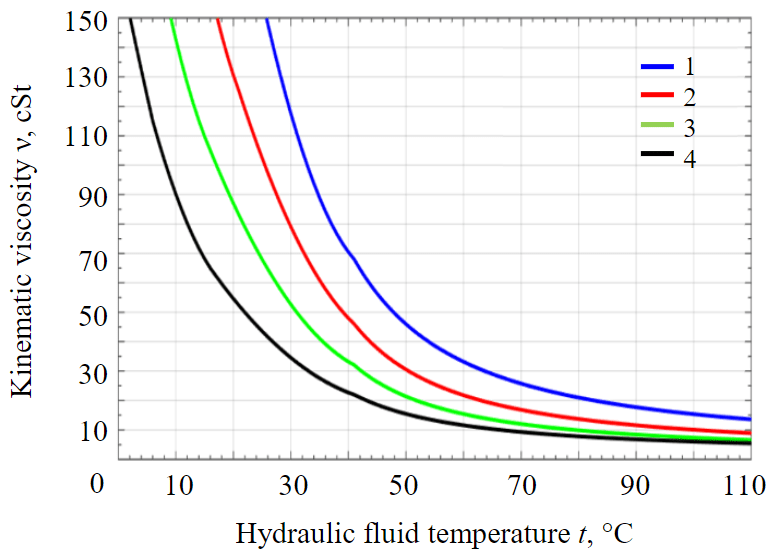
Fig.1. Viscosity curves for hydraulic fluids according to temperature 1 – Shell Tellus S2 V 68; 2 – S2 V 46; 3 – S2 V 32; 4 – S2 V 22
The dependence of the viscosity of Shell Tellus hydraulic fluids used in mining hydraulic excavators on temperature is shown in Fig.1.
The calculation of power losses during the operation of a mining hydraulic excavator involves the calculation of pressure losses in hydraulic components (pipelines, valves and fittings), power losses due to hydraulic fluid leaks, primarily of the main pumps and hydraulic motors. The total pressure losses by pipe length are determined by the Darcy – Weisbach formula for a viscous fluid flow
where i is the number of straight sections of the hydraulic pipe; λi is the flow coefficient for the corresponding hydraulic line; Li, di are the length and internal diameter of the i-th pipeline respectively; vi is the average flow rate of the hydraulic fluid of the i-th pipeline [10, 13, 14].
The value of the flow coefficient depends on the type of fluid flow (Laminar and Turbulent). After a long downtime, immediately after starting the hydraulic system, when the fluid has not yet warmed up, laminar flow can be observed in the channels and the flow coefficient is usually calculated using the Poiseuille formula [10, 14, 15]
Further, in a turbulent flow, the Blausius formula is used [14-16]
where Re is the Reynolds number of the hydraulic fluid flow in the pipeline.
Losses also occur when the fluid passes through local resistances – fittings, valves, hydraulic control devices. The magnitude of these pressure losses is calculated using the following formula [14, 17]
where K is the pressure drop coefficient. Values are determined from reference literature or experimentally.
The work cycle of the piston chamber of an axial piston pump consists of the processes suction and discharge of the hydraulic fluid. The reason for the hydraulic fluid leakage in the pump is a large pressure difference between the piston chamber and the casing. Volume losses occur when liquid is forced into the pressure line. Fluid leakage from the working chamber consists of the following four components: leakage through the gap between the piston and the piston chamber wall Qpc, through the gap between the piston and the slipper Qps, through the gap between the slipper and the swash plate Qss and through the gap between the cylinder block and valve plate Qcv (Fig.2, a).
Hydraulic fluid leakage through the annular gap between the piston and the piston chamber wall is determined by the expression [10, 17, 18]
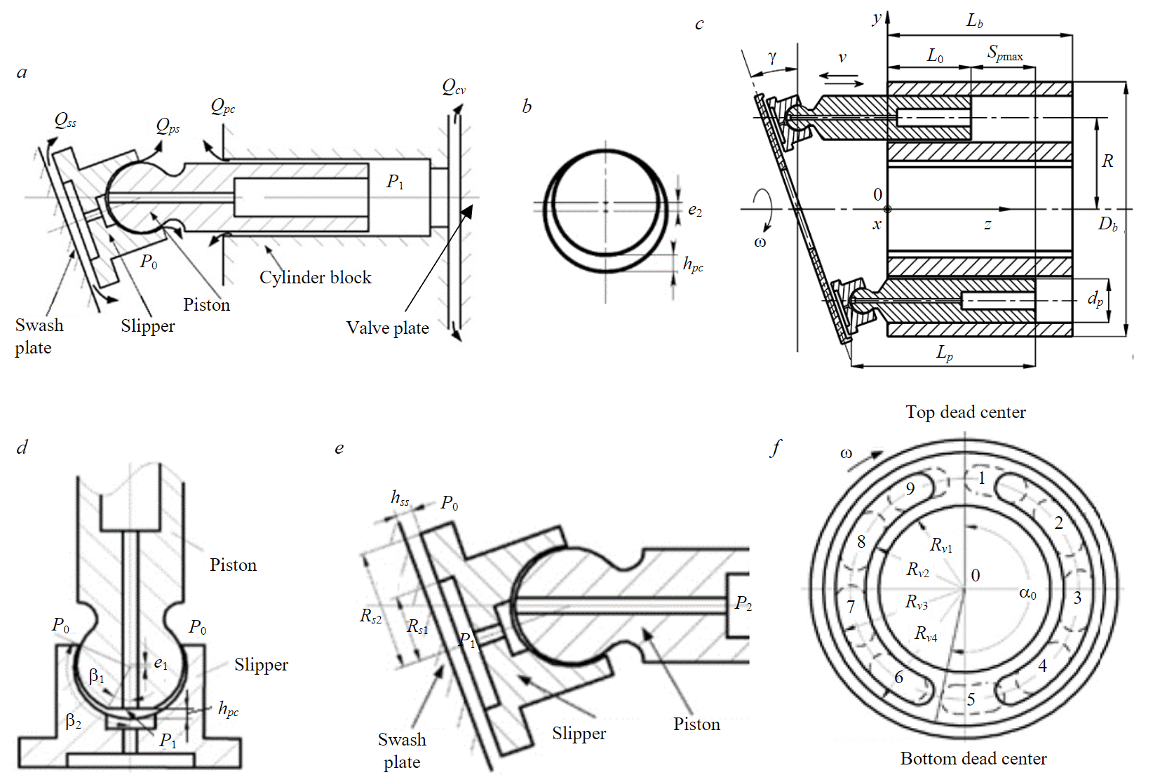
Fig.2. Leakage of hydraulic fluid in the axial plunger pump and hydraulic motor
where dp is the piston diameter, m; hpc is the gap width between the piston and the piston chamber wall, m; P1, P0 are the pressure in the piston chamber and in the casing respectively, Pa; μ is the hydraulic fluid dynamic viscosity, Pa·s; l is the length of the piston part in the piston chamber, m; η = e/hpc is the relative eccentricity; e is the eccentricity of the piston relative to the cylinder, m; v – is the speed of the piston in the piston chamber, m/s (Fig.2, b, c) [10].
Hydraulic fluid leaks in the spherical hinge between the piston and the slipper are determined by the expression [10, 17, 18]
where hps is the spherical hinge gap width, m; P1, P0 are the pressure in the slipper chamber and in the pump casing, respectively, Pa; β1, β2 are design angles of the spherical joint of the piston and slipper, rad (Fig.2, d).
Hydraulic fluid leaks through the gap between the slipper and the swash plate are determined by the formula [10, 18, 19]
where hss is the width of the gap between the slipper and the swash plate, m; Rs1 is the groove and Rs2 is the outer radius of piston slipper, m (рис.2, e).
Hydraulic fluid leaks through the gap between the cylinder block and the valve plate, is determined by the expression [10, 18, 20]
where hcvis the width of the gap between the cylinder block and the valve plate, m; Rv1, Rv2, Rv3, Rv4 are the valve plate dimensions, m (Fig.2, f).
Summing up the results of formulas (1)-(4), taking into account the operating cycle of the piston chambers and the pump construction, we obtain
where z is the number of piston chambers.
Taking into account the assumptions made, the total power loss in the hydraulic system of a mining excavator can be written [21-23]
where Qw is the hydraulic fluid flow rate, m3/s; Δp is the pressure loss in the hydraulic system, Pa; Qs1 is the total leakage of the hydraulic fluid in pumps and hydraulic motors, m3/s; р is the hydraulic system pressure, Pa.
The mathematical model used for programming calculations in the MatLab Simulink software is based on the considered equations and expressions. The main parameters used in calculations and modeling are the actual parameters of Komatsu PC750-7 mining excavator hydraulic system according to the manufacturer's catalog (Table 2).
Table 2
Initial parameters for modeling
|
Hydraulic system component |
Parameters |
|
Hydraulic fluid Shell Tellus S2 V 440 |
Density at t = 15 °C: ρ = 872 kg/m3 |
|
Main pump HPV160+160 2 pc. |
Piston diameter dp = 22.5 mm |
|
Piston length Lp = 100 mm |
|
|
Piston pitch radius Rp = 49.5 mm |
|
|
Swash plate angle γ = 19.5° |
|
|
Minimum piston length in piston chamber l0 = 45 mm |
|
|
Number of piston chambersz = 9 |
|
|
Shaft speedn = 2400 min–1 |
|
|
Piston chamber working pressure Ps = 31 MPa |
|
|
Pump casing pressure P0 = 1.5 MPa |
|
|
Piston slipper design dimensions Rs1 = 8 mm; Rs2 = 13° |
|
|
Design angles of the piston and slipper spherical b1 = 14°; b2 = 119° |
|
|
Valve plate design dimensions Rv1 = 29 mm; Rv2 = 38 mm; Rv3 = 50 mm; Rv4 = 60 mm; a0 = 193° |
|
|
Swing motors (axial piston) 2 pc. |
Displacement q1 = 255 cm3 |
|
Shaft speed260 min–1 |
|
|
Working pressure 28.4 MPa |
|
|
Power 31.4 kWt |
|
|
Mechanical efficiency ηmc = 0.98 |
|
|
Volumetric efficiency ηvl = 0.96 |
|
|
Boom lift cylinders 2 pc. |
Flow rate at: |
|
digging 0.0018 m3/s |
|
|
swing load 0.0013 m3/s |
|
|
loading 0.0014 m3/s |
|
|
swing empty 0.00144 m3/s |
|
|
Hydraulic pipe inner diameter dpBlin = 19.05 mm |
|
|
Hose length LpBl = 13.4 m |
|
|
Arm cylinders 2 pc. |
Flow rate at: |
|
digging 0.002 m3/s |
|
|
swing load 0.00014 m3/s |
|
|
loading 0.00105 m3/s |
|
|
swing empty 0.001903 m3/s |
|
|
Hydraulic pipe inner diameter dpAcin = 19.05 mm |
|
|
Hose length LpAc = 23 m |
|
|
Bucket cylinders 1 pc. |
Flow rate at: |
|
digging 0.00191 m3/s |
|
|
swing load 0.001804 m3/s |
|
|
loading 0.0021 m3/s |
|
|
swing empty 0.00115 m3/s |
|
|
Hydraulic pipe inner diameter dpBcin = 19.05 mm |
|
|
Hose length LpBc = 23 m |
|
|
Oil cooler 1 pc. |
Oil cooler oval pipes dimensions: a = 22.1 mm; b = 6 mm; δpp = 0.75 mm |
|
Number of pipe rows zrow = 3 |
|
|
Number of pipes in a row mrow = 51 |
|
|
Hose length LpOc = 1290 mm |
|
|
Filters 5 pc. |
Pressure drop coefficients 5-12 |
|
Directional control valves 3 pc. |
Pressure drop coefficients 3-5 |
|
Throttle valves 3 pc. |
Pressure drop coefficients 0-100 |
|
Elbows 90° 34 pc. |
Pressure drop coefficients 1 |
|
Check valves 5 pc. |
Pressure drop coefficients 1-5 |
|
Pump suction line dimensions |
Diameter 35 mm |
|
Length 2.5 m |
Numerical modeling of physical processes has found wide application in the field of studying the processes of mining hydraulic excavators, since it allows taking into account a large number of quantities that change according to nonlinear dependencies and solving previously considered problems with much greater accuracy [24-26]. For computer simulation of power losses in a hydraulic system, the developed calculation method and a software algorithm implemented in the MatLab Simulink environment were used.
Discussion of the results
The preparation of a numerical experiment required an analysis of the Komatsu PC750-7 mining hydraulic excavator operating cycle [27-29]. The accurate values of flow rates in various sections of the hydraulic lines, as well as in individual devices of the hydraulic system of the excavator, were calculated, which is important for accurately determining energy losses [30-32]. As a result of the simulation, the values of power losses during the execution of work operations at various temperatures were obtained, presented in Table 3.
Table 3
Power loss during work operations, kWt
|
Hydraulic fluid temperature t, °C |
Digging |
Swing load |
Loading |
Swing empty |
Volumetricleakages |
|
0 |
390.2 |
110.3 |
269.3 |
222.5 |
1.6 |
|
20 |
126.3 |
41.73 |
90.08 |
76.23 |
5.99 |
|
30 |
90.78 |
32.44 |
65.92 |
56.42 |
9.64 |
|
40 |
71.43 |
27.51 |
52.34 |
45.74 |
15.2 |
|
50 |
58.41 |
24.34 |
43.69 |
38.73 |
24 |
|
55 |
54.66 |
23.39 |
41.16 |
36.68 |
28.71 |
|
60 |
51.87 |
22.69 |
39.28 |
35.15 |
33.56 |
|
70 |
48.04 |
21.71 |
36.69 |
33.04 |
43.51 |
|
80 |
45.54 |
21.07 |
35.02 |
31.67 |
53.62 |
|
90 |
43.8 |
20.61 |
33.85 |
30.71 |
63.76 |
|
110 |
41.52 |
20.02 |
32.33 |
29.45 |
83.78 |
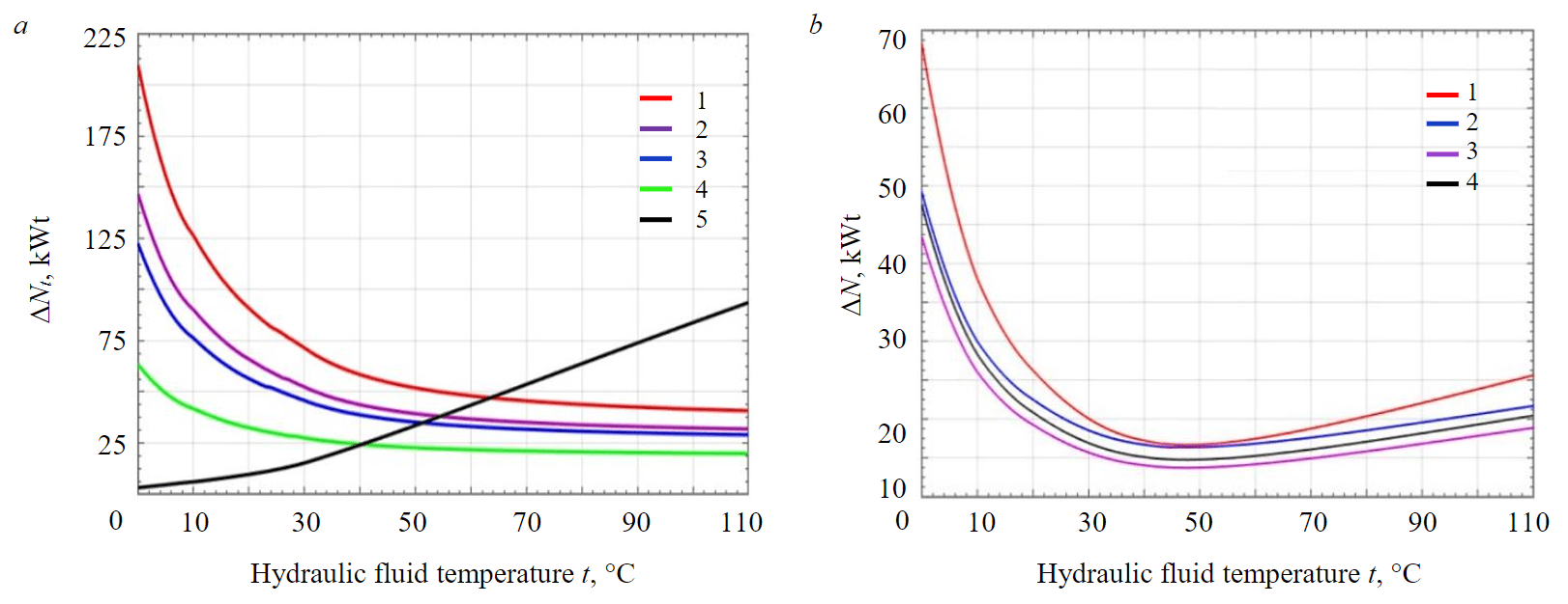
Fig.3. Power loss depending on the hydraulic fluid temperature: a – due to hydraulic fluid leaks, pressure losses in hydraulic components (lines, valves etc.)(1 – digging; 2 – swing load; 3 – swing empty; 4 – loading; 5 – main pumps) b – total power losses during the implementation of work processes(1 – digging; 2 – swing load; 3 – loading; 4 – swing empty)
Figure 3 shows power losses due to hydraulic fluid leakage and pressure losses in hydraulic components (lines, valves etc.) depending on the hydraulic fluid temperature for the working cycle operations: digging, swing load, loading, swing empty.
From the presented graphical dependences it is clearly seen that the energy losses during various working operations differ significantly from each other, which does not contradict the previously published results [33-35]. As the temperature of the liquid increases, the power loss caused by to hydraulic losses due to the properties of pipelines and associated resistances will decrease, while the increase in power due to the volume of leaks increases.
The values of the total power loss ∆N for different operations of the excavator working cycle differ in value, but they all have a common feature, which is that the total power loss decreases with an increase in the hydraulic fluid temperature from 0 to 30-35 °C, reaching the lowest value in the temperature range from 35 to 55 °C. After 55 °C, the power loss increases rapidly with the temperature rise. Since leaks in the control devices of the hydraulic system were not taken into account at this stage of the research, power losses with increasing temperature in the example under consideration will be the lower limit of values.
The total power loss versus temperature for various hydraulic fluids is shown in Fig.4. The presented graphic dependences clearly show a significant energy overspending when working on unheated hydraulic oil and the need to warm it up to 30-40 degrees before starting work.
It follows from these dependencies that when the excavator is operating in winter conditions, it is more advisable to use hydraulic fluids with a lower viscosity, and when working in a hot climate, for example, in the conditions of the Socialist Republic of Vietnam, it is advisable to use hydraulic fluids with increased viscosity. The optimal temperature value depends on the viscosity and other characteristics of the fluid, but it also depends on the hydraulic system elements technical condition and mining operating factors that affect the duration of the working cycles. Therefore, absolute value of power losses in certain conditions, are not an informative indicator.
To assess the energy efficiency of the mining excavator hydraulic system, a power loss coefficient is proposed. It is defined as the ratio of the minimum possible power losses in the hydraulic system in the considered operating conditions to the actual ones:
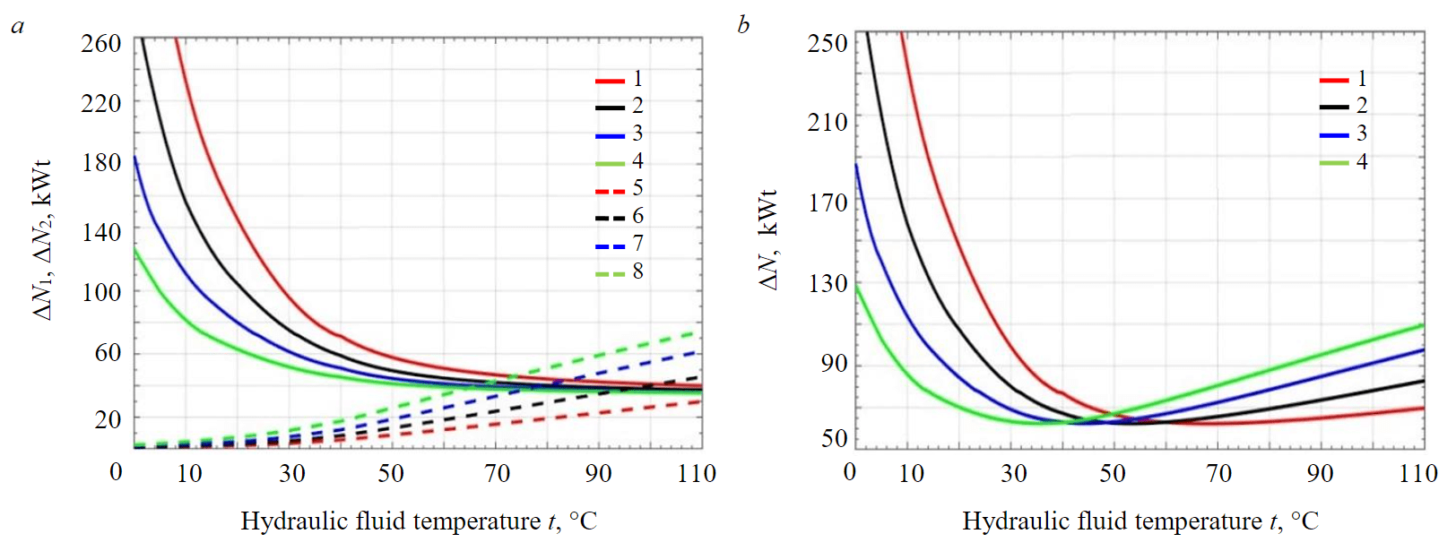
Fig.4. Power loss depending on temperature for various hydraulic fluids:a – due to hydraulic fluid leaks, pressure losses in hydraulic components (lines, valves etc.)(1, 5 – ΔN1 и ΔN2 using Shell Tellus S2 V 68; 2, 6 – ΔN1 и ΔN2 using Shell Tellus S2 V 46; 3, 7 – ΔN1 и ΔN2 using Shell Tellus S2 V 32; 4, 8 – ΔN1 и ΔN2 using Shell Tellus S2 V 22) b – general power losses during the work processes(1 – ΔN using Shell Tellus S2 V 68; 2 – using Shell Tellus S2 V 46; 3 – using Shell Tellus S2 V 32; 4 – using Shell Tellus S2 V 22)
where ΔNmin is the minimum possible power loss in given conditions; ΔNf is the actual power loss.
The value of the power loss coefficients when using various hydraulic fluids is shown in Fig.5. The concept of “temperature range of power loss – Trpl” is proposed – the temperature interval between the minimum and maximum temperatures, corresponding to the value of the power loss coefficient.
The temperature range at the value of the power loss coefficient of 0.8; 0.9; 0.95 for liquids with different viscosities in the conditions under consideration is presented in Table 4: ν is the hydraulic fluid kinematic viscosity; toptis the temperature value for the lowest energy losses; t–А, t+А are the smallest and largest temperature values in the interval under consideration; t–Ot, t+Ot are the value of the temperature interval from topt to t–A, t+A; t+-t– are the value of the temperature interval from t–A to t+A.
Table 4
The value of the temperature range for different viscosities of hydraulic fluids
|
ν, cSt |
topt |
Kpl = 0.8 |
Kpl = 0.9 |
Kpl = 0.95 |
|||||||||||||
|
t–A |
t–Ot |
t+A |
t+Ot |
t+-t– |
t–A |
t–Ot |
t+A |
t+Ot |
t+-t– |
t–A |
t–Ot |
t+A |
t+Ot |
t+-t– |
|||
|
22 |
35 |
12 |
23 |
68 |
33 |
56 |
20 |
15 |
52 |
17 |
32 |
25 |
10 |
45 |
10 |
15 |
|
|
32 |
44 |
24 |
20 |
79 |
35 |
55 |
30 |
14 |
62 |
18 |
32 |
32 |
12 |
53 |
9 |
21 |
|
|
46 |
55 |
30 |
25 |
100 |
45 |
70 |
38 |
17 |
80 |
35 |
42 |
42 |
13 |
70 |
15 |
28 |
|
|
68 |
68 |
40 |
28 |
> 110 |
> 45 |
80 |
48 |
20 |
108 |
50 |
60 |
52 |
16 |
95 |
27 |
43 |
|
From the graphical dependencies and the data presented in Table 4, it follows that with an increase in viscosity, the difference in the values of the high and optimal temperatures increases, as well as the value of the “power loss interval” corresponding to the specified Kpl value.
Conclusion
A method for calculating power losses in the hydraulic system of a mining hydraulic excavator depending on temperature is proposed. The method is implemented using the MatLab Simulink program on the example of Shell Tellus SV 2 46 hydraulic fluid and the hydraulic system of the Komatsu PC750-7 excavator.
- In the range from zero to 30-50 degrees, 70-80 % of power losses are pressure losses in hydraulic components (lines, valves etc.), which decrease in a quadratic relationship with a decrease in the hydraulic fluid viscosity caused by an increase in temperature. After 30-50 degrees, with a further decrease of hydraulic fluid viscosity, due to an increase in hydraulic fluid leaks in pumps and hydraulic motors, the main power losses increase according to a dependence close to a straight line, the angle of inclination of which is determined by the technical condition of the hydraulic motors and pumps, primarily the main pumps, the parameters of the hydraulic fluid, and mining factors of operation.
- A criterion for estimating energy losses in the hydraulic system of a mining hydraulic excavator depending on the hydraulic fluid temperature is proposed – the power loss coefficient Kpl, obtained by comparing the minimum possible losses at the optimum temperature in given conditions with energy losses at the actual temperature. The use of the proposed coefficient will allow estimating “excessive” energy losses when deviating from a range close to the optimal temperature of the hydraulic fluid in the conditions under consideration and hydraulic systems of other machines.
- The concept of “temperature range of power loss – Trpl” is proposed – the temperature interval between the minimum and maximum temperatures, corresponding to the value of the power loss coefficient.
- Calculations have shown that the implementation of measures that ensure operation in the interval with a deviation of 10 % from the optimal temperature value (Kpl ≥ 0.9) for these conditions, can reduce energy losses from 3 to 12 %.
References
- Pudov E.Yu., Zang K.K., Kuzin E.G., Krivenko A.E. Assessment of the impact of operating conditions on the performance of the hydraulic mining excavator working fluid cooling system. Mining Equipment and Electromechanics. 2021. N 1, p. 51-58 (in Russian). DOI: 10.26730/1816-4528-2021-1-51-58
- Özmen Ö., Sınanoğlu C., Batbat T., Güven A. Prediction of Slipper Pressure Distribution and Leakage Behaviour in Axial Piston Pumps Using ANN and MGGP. Mathematical Problems in Engineering. Vol. 2019. N 7317520, p. 1-13. DOI: 10.1155/2019/7317520
- Bergada J.M., Kumar S., Davies D.L., Watton J. A complete analysis of axial piston pump leakage and output flow ripples. Applied Mathematical Modelling. 2012. Vol. 36. Iss. 4, p. 1731-1751. DOI: 10.1016/j.apm.2011.09.016
- Komissarov A.P., Lagunova Yu.A., Shestakov V.S., Ivanov I.Yu. Single-bucket excavator energy demand. Gornyi zhurnal. 2018. N 1, p. 73-77 (in Russian). DOI: 10.17580/gzh.2018.01.13
- Juza M., Hermanek P. Study of the energy efficiency of the UDS 214 excavator hydraulic system. MM Science Journal. 2022. Iss. 3, p. 5768-5774. DOI: 10.17973/MMSJ.2022_10_2022077
- Casoli P., Scolari F., Vescovini C.M. et al. Excavator hydraulic circuit solution to reduce dissipations and fuel consumption. E3S Web of Conferences. 2021. Vol. 312. N 05004. DOI: 10.1051/e3sconf/202131205004
- Balakhnina E., Vykhodtseva G., Sizova E. et al. Theoretical interpretation of the function of changing the tractive effort of a quarry locomotive in the starting mode. AIP Conference Proceedings. International Conference on Modern Trends in Manufacturing Technologies and Equipment 2021, 6-10 September 2021, Sevastopol, Russia. AIP Publishing, 2022. Vol. 2503. Iss. 1. N 050049. DOI: 10.1063/5.0100861
- Balakhnina E., Sizova E., Vykhodtseva G., Mishedchenko O. Investigation of the Dependence of the Friction Coefficient Change on the Speed under Rational Starting Modes of a Quarry Locomotive. AIP Conference Proceedings, International Conference on Modern Trends in Manufacturing Technologies and Equipment 2021, 6-10 September 2021, Sevastopol, Russia. AIP Publishing, 2022. Vol. 2503. Iss. 1. N 050048. DOI: 10.1063/5.0100597
- Pudov E.Yu., Zang K.K., Kuzin E.G. et al. Influence of ambient temperature and type of working fluid on thermodynamic equilibrium of hydraulic system of excavators. Mining Equipment and Electromechanics. 2021. N 1, p. 45-50 (in Russian). DOI: 10.26730/1816-4528-2021-1-45-50
- Zang K.K. Justification and selection of the hydraulic system oil cooler parameters of a mining hydraulic excavator when operating in the conditions of the Republic of Vietnam: Avtoref. dis. … kand. tekhn. nauk. Moscow: MISiS, 2021, p. 21 (in Russian).
- Abduazizov N.A., Muzaffarov A., Toshov J.B. et al. A complex of methods for analyzing the working fluid of a hydrostatic power plant for hydraulic mining machines. International Journal of Advanced Science and Tehnology. 2020. Vol. 29. SI5, p. 852-855.
- Abduazizov N.A., Dzhuraev R.U., Zhuraev A.Sh. Study of the effect of temperature and viscosity of the hydraulic fluid of hydraulic systems on the reliability of mining equipment. Gornyi vestnik Uzbekistana. 2018. N 3 (74), p. 58-60 (in Russian). DOI: 10.13140/RG.2.2.11942.96329
- Xia Lianpeng, Quan Long, Cao Donghui et al. Research on Energy Saving Characteristics of Large Hydraulic Excavator Boom Driven by Dual Hydraulic-gas Energy Storage Cylinder. Journal of Mechanical Engineering. 2019. Vol. 55. Iss. 20, p. 240-248. DOI: 10.3901/JME.2019.20.240
- Yusuf S.I., Ejeh S., Olayiwola R.O. Analytical Study of Leakage of Viscous Flow in a Cylindrical Pipe. International Journal of Scientific Engineering and Applied Science. 2022. Vol. 8. Iss. 3, p. 74-93.
- Siddique M.A.A., Yong-Joo Kim, Wan-Soo Kim et al. Effects of Temperatures and Viscosity of the Hydraulic Oils on the Proportional Valve for a Rice Transplanter Based on PID Control Algorithm. Agriculture. 2020. Vol. 10. Iss. 3. N 73. DOI: 10.3390/agriculture10030073
- Lukashuk O.A., Komissarov A.P., Letnev K.Y. Increasing power efficiency of open-pit excavators. IOP Conference Series: Materials Science and Engineering. 2020. Vol. 709. Iss. 2. N 022083. DOI: 10.1088/1757-899X/709/2/022083
- Ruichuan Li, Jilu Liu, Xinkai Ding, Qi Liu. Study on the Influence of Flow Distribution Structure of Piston Pump on the Output of Pulsation Pump. Processes. 2022. Vol. 10. Iss. 6. N 1077. DOI: 10.3390/pr10061077
- Haocen Hong, Chunxiao Zhao, Bin Zhang et al. Flow Ripple Reduction of Axial-Piston Pump by Structure Optimizing of Outlet Triangular Damping Groove. Processes. 2020. Vol. 8. Iss. 12. N 1664. DOI: 10.3390/pr8121664
- Shishlyannikov D., Zverev V., Ivanchenko A., Zvonarev I. Increasing the Time between Failures of Electric Submersible Pumps for Oil Production with High Content of Mechanical Impurities. Applied Sciences. 2022. Vol. 12. Iss. 1. N 64. DOI: 10.3390/app12010064
- Xingjian Wang, Siru Lin, Shaoping Wang et al. Remaining useful life prediction based on the Wiener process for an aviation axial piston pump. Chinese Journal of Aeronautics. 2016. Vol. 29. Iss. 3, p. 779-788. DOI: 10.1016/j.cja.2015.12.020
- Yingxiao Yu, Tri Cuong Do, Bifeng Yin, Kyoung Kwan Ahn. Improvement of Energy Saving for Hybrid Hydraulic Excavator with Novel Powertrain. International Journal of Precision Engineering and Manufacturing-Green Technology. 2023. Vol. 10. Iss. 2, p. 521-534. DOI: 10.1007/s40684-022-00437-9
- Hidayat H., Aviva D., Muis A. et al. Failure analysis of excavator hydraulic pump. IOP Conference Series: Materials Science and Engineering. 2022. Vol. 1212. Iss. 1. N 012052. DOI: 10.1088/1757-899X/1212/1/012052
- Makarova V.V., Lagunova Yu.A., Kovyazin R.A., Nesterov V.I. A new approach to creation of hydraulic excavators. Mining Equipment and Electromechanics. 2021. N 6, p. 9-14 (in Russian). DOI: 10.26730/1816-4528-2021-6-9-14
- Litvin O.I., Markov S.O., Khoreshok А.A. et al. Determination of the area of energy-efficient position of working equipment and effective digging radius of hydraulic excavators at open pit mining. Mine surveying and subsurface use. 2022. N 4 (120), p. 38-44 (in Russian). DOI: 10.56195/20793332_2022_4_38
- Kujundžić T., Klanfar M., Korman T., Briševac Z. Influence of Crushed Rock Properties on the Productivity of a Hydraulic Excavator. Applied Sciences. 2021. Vol. 11. Iss. 5. N 2345. DOI: 10.3390/app11052345
- Holt G.D., Edwards D. Analysis of interrelationships among excavator productivity modifying factors. International Journal of Productivity and Performance Management. 2015. Vol. 64. N 6, p. 853-869. DOI: 10.1108/IJPPM-02-2014-0026
- Komissarov A.P., Lagunova Yu.A., Lukashuk O.A., Shestakov V.S. Software management of the rock excavation process by a quarry excavator. Mining Equipment and Electromechanics. 2020. N 5, p. 28-33 (in Russian). DOI: 10.26730/1816-4528-2020-5-28-33
- Litvin O.I., Khoreshok A.A., Dubinkin D.M. et al. Analysis of methods for calculating the productivity of open-pit hydraulic shovels and backhoes. Russian Mining Industry. 2022. N 5, p. 112-120 (in Russian). DOI: 10.30686/1609-9192-2022-5-112-120
- Komissarov A.P., Lagunova Yu.A., Nabiullin R.Sh., Khoroshavin S.A. Digital model of shovel work process. Mining Informational and Analytical Bulletin. 2022. N 4, p. 156-168 (in Russian). DOI: 10.25018/0236_1493_2022_4_0_156
- Litvin O., Litvin Y. Evaluation of Effect of the Excavator Cycle Duration on its Productivity. E3S Web of Conferences. Vol. 174. N 01010, p. 1-5. DOI: 10.1051/e3sconf/202017401010
- Sobolevskyi R., Korobiichuk V., Levytskyi V. et al. Optimization of the process of efficiency management of the primary kaolin excavation on the curved face of the conditioned area. Rudarsko-geološko-naftni zbornik. 2020. Vol. 35. N 1, p. 123-138. DOI: 10.17794/rgn.2020.1.10
- Klanfar M., Herceg V., Kuhinek D., Sekulić K. Construction and testing of the measurement system for excavator productivity. Rudarsko-geološko-naftni zbornik. 2019. Vol. 34. N 2, p. 51-58. DOI: 10.17794/rgn.2019.2.6
- Cheol-Gyu Park, Seungjin Yoo, Hyeonsik Ahn et al. A coupled hydraulic and mechanical system simulation for hydraulic excavators. Proceedings of the Institution of Mechanical Engineers, Part I: Journal of Systems and Control Engineering. 2019. Vol. 234. Iss. 4, p. 527-549. DOI: 10.1177/0959651819861612
- Ng F., Harding A.J., Glass J. An eco-approach to optimise efficiency and productivity of a hydraulic excavator. Journal of Cleaner Production. 2016. Vol. 112. Part 5, p. 3966-3976. DOI: 10.1016/j.jclepro.2015.06.110
- Juraev A. Study of the Effect of Hydraulic Systems Operation on the General Performance of a Hydraulic Excavator. The American Journal of Engineering and Technology. 2021. Vol. 3. Iss. 10, p. 36-42. DOI: 10.37547/tajet/Volume03Issue10-07