
Evaluation of the energy efficiency of functioning and increase in the operating time of hydraulic drives of sucker-rod pump units in difficult operating conditions
- 1 — Ph.D., Dr.Sci. Perm National Research Polytechnic University ▪ Orcid
- 2 — Ph.D. Perm National Research Polytechnic University ▪ Orcid
- 3 — Ph.D. Assistant Lecturer Saint Petersburg Mining University ▪ Orcid
- 4 — Assistant Lecturer Perm National Research Polytechnic University ▪ Orcid
- 5 — Assistant Lecturer Perm National Research Polytechnic University ▪ Orcid
Abstract
The necessity of improving the drives of the sucker-rod hydraulic pump units (SRHP), operated in conditions of marginal and complicated wells, is substantiated. For complicated oil production conditions, it is promising to use the SRHP drive, which makes it possible to select and set rational operating modes for downhole equipment. The results of comparative tests of conventional mechanical and hydraulic actuators SRHP with pneumatic and electrodynamic balancing types are presented. A generalized indicator for evaluating the effectiveness of the advanced SRHP drives functioning, the energy efficiency coefficient, is proposed. It has been experimentally proven that the use of the SRHP drive with pneumatic balancing is characterized by low energy efficiency of the well fluid production process. The use of the tested SRHP hydraulic drive made it possible to successfully eliminate asphalt, resin, and paraffin deposits and minimize the well downtime. The results of the tests of the traditional SRHP mechanical drive and the hydraulic drive with electrodynamic balancing showed a satisfactory energy efficiency of the latter. The advantage of the SRHP drive with electrodynamic balancing is the simplicity of the design of the hydraulic part. The process of energy regeneration during the drive control system operation causes an increase in the reactive power component in the oil field network and the appearance of harmonic interference that adversely affects the consumers operation. Technical solutions aimed at improving the operation energy efficiency and increasing the operating time of SRHP drives in the conditions of marginal and complicated wells are proposed. The methodological bases for assessing the economic efficiency of the introduction of the advanced SRHP drives are given.
The research was supported by the Ministry of Science and Higher Education of the Russian Federation (Project N FSNM-2023-0005)
Introduction
A significant number of production wells in the oil fields of Russia and neighboring countries are at the final (third and fourth) operation stages. Such wells are characterized by low flow rates (Q = 1-15 m3/day) and the presence of factors that complicate the operation of submersible equipment [1-3]. A low-yield and complicated oil wells operation is carried out mainly with the use of sucker-rod hydraulic pump units (SRHP), equipped with a mechanical drive – balan-cing pumping units (SK) [4]. In the delivery ranges of sucker rod pumps of Q = 30-45 m3/day, SRHP is characterized by a fairly high energy efficiency, the efficiency of a serviceable installation is η = 0.36-0.54.
The presence of complicating factors and low well flow rates cause a sharp decrease in the efficiency of the SRHP (η = 0.02-0.05 with a power factor of the SK drive motors not exceeding cosφ = 0.3) [5]. As a result, the performance indicators of the SRHP are significantly reduced, while the cost of oil production, on the contrary, is unreasonably increased [6]. The value of specific energy consumption for the well fluid lifting using conventional SRHP for low-rate and complicated wells is 5-10 times higher than similar values for medium- and high-rate wells [7, 8].
The use of SRHP non-balance drives, which make it possible to ensure long-stroke operating modes of downhole pumps and increase the installation energy efficiency during the marginal well operation, is limited by the flexible links (chains, V-belts, steel ropes, etc.) low reliability. This fact causes the frequent replacement of the short-lived elements of the flexible links, equipment downtimes and, as a consequence, oil companies significant material losses.
In the works of domestic and foreign researchers, it is indicated that one of the ways to improve the SRHP operation efficiency and reliability during the marginal and complicated wells operation is the use of a hydraulic drive (HD) [9, 10]. SRHP drive is characterized by mobility, low material consumption, ease of adjustment and wide ranges of change in operational parameters. These advantages make it possible to select and set the SRHP HD operation modes, which are rational in terms of the unit energy consumption for lifting the formation fluid, as well as to increase the efficiency of implementing the technical and technological measures to eliminate the negative consequences of complicating factors [11, 12].
The tasks of evaluating the energy efficiency of the serially produced SRHP HD and developing technical solutions aimed at improving the reliability of their operation in difficult operating conditions are both relevant and of scientific and practical interest.
Methods
The development and trial operation of SRHP HD started in the USA in the 40s of the XX century. Specialists of Vickers, Pelton, Axelson companies created and tested original designs of SRHP HD, which had worse performance characteristics compared to balancing SK, which led to their low distribution. At the same time, compactness, mobility, and wide possibilities for automating the operation of these drives determined the prospects for research aimed at their further improvement. Domestic specialists developed SRHP HD, the design schemes of which are similar to those used abroad, and proposed the original solutions, for example, the installation of an acceleration graphic point (AGP) designed by professor G.V.Molchanov [11]. The general classification of SRHP HD according to design features is given in Table 1.
Table 1
SRHP HD design features classification [11]
|
Kinematic connection of the power body and the balancing device |
Balancing method |
|||||
|
Static |
Dynamic |
Unbalanced |
||||
|
Pheumatic |
Loading |
Mutual |
Inertial |
Electro-dynamic |
||
|
Hydraulic |
Pneumatic accumulator drive |
Drive with individualload. installations with tubingas a balancing weight |
Mutual balancing of two or more installations |
Using a flywheel with an individual drive |
– |
Unbalanced drives |
|
Mechanical rigid |
– |
Balanced rigid connection |
– |
Using a flywheel mounted on the motor shaft |
Machine operation in generator mode |
Partially balanced drives |
|
Mechanical flexible |
– |
Balancing load on rope suspension |
– |
– |
– |
– |
Modern mass-produced samples of SRHP HD are equipped with systems for monitoring operation parameters and self-diagnostics: by monitoring the pressure values in the discharge pipelines, dynamometering is carried out, i.e. assessment of the load, technical condition and efficiency of the downhole pumping equipment. The position control of the rod string suspension point position, the polished rod stroke and oscillation frequency is carried out by means of sensors (magnetic type markers).
The factors that have the greatest impact on the SRHP HD operation efficiency and the amount of their operating time in the oil field conditions include: the adopted balancing method; the performed balancing quality; energy transfer method from the balancing device to the power body; power structure [5].
The choice of the SRHP HD balancing device is carried out taking into account its energy intensity, operational stability (reduced durability), pre-charging technology at the initial start-up, as well as maintaining and regulating the installation operation mode (Table 2) [11].
Table 2
SRHP HD balancing device main parameters
|
Parameter |
Balancing device |
||
|
Pneumatic |
Weighing |
Inertial |
|
|
Specific energy intensity, kJ/kg |
25-30 |
1-6 |
100-200 |
|
Efficiency, % |
97 |
98 |
95 |
|
Energy storage time, h |
Not limited |
Not limited |
0.05-0.1 |
|
Number of charge-discharge cycles |
107 |
Not limited |
Not limited |
|
Reduced durability (per 1 m of SRSP stroke), h |
1.7·104 |
Not limited |
Not limited |
The task of balancing the SRHP HD in practice can be solved in several ways, which differ in the accepted balancing criteria [13]: balancing by maximum loads, by the average work value or the standard deviation from the average work value of. These criteria have been developed for balancing SK, which are characterized by machine load mode that is different from the load of the SRHP HD machine. For a balanced SK, the torque change law on the motor shaft is close to a sinusoid, while for a balanced hydraulic drive it is characterized by a graph close to a straight line [1].
The SRHP drive is considered to be perfectly balanced if the instantaneous power at any moment of time is constant and equal to the average power developed by the motor in one drive cycle [14]. Since it is difficult to ensure the electric motor instantaneous power constancy during the SRHP HD operation cycle, the equilibrium condition is determined based on the minimum power dispersion for the full cycle of SRHP HD operation [11]. It follows that it is rational to determine balancing quality assessment and the SRHP HD functioning energy efficiency in the oil field conditions by continuously measuring the electric motor power during the drive operation and subsequent analysis of the obtained measurement from the wattmeters [15, 16].
In the oil fields of Russia and the countries of the near abroad, the SRHP HD with pneumatic and electrodynamic balancing are most widely used. They consist of a pumping station and a power hydraulic cylinder that provides reciprocating movement of the sucker rod suspension point (SRSP), are equipped with remote control systems, remote monitoring and built-in self-diagnostics systems, which allows you to quickly change the operating parameters of the SRHP HD and downhole equipment [11].
Together with the specialists of OOO “LUKOIL-Perm”, the studies to assess the load and energy efficiency of the operation of the SRHP HD with pneumatic and electrodynamic balancing were carried out. The research program included the performance of comparative tests of SRHP drives – mechanical balancing drives SK-8 and serially produced SRHP HD: with pneumatic balancing NPK-10-8-6 (Fig.1, a); with electrodynamic balancing SRHP HD 80-3.5 “Geyser” (Fig.1, b).
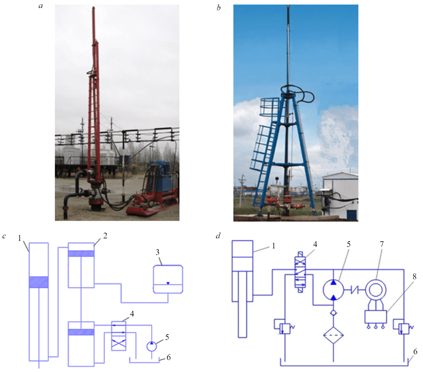
Fig.1. SRHP drives general view (a, b) and schematic hydraulic diagrams (c, d): a, c – NPK-10-8-6; b, d – SRHP HD 80-3.5 “Geyser” 1 – power hydraulic cylinder; 2 – intermediate hydraulic cylinder; 3 – pneumatic accumulator; 4 – hydraulic distributor; 5 – hydraulic pump; 6 – tank; 7 – electric motor; 8 – block of intelligent control system
Evaluation of the change nature and the load magnitude of the SRHP HD, the surveyed pumping units energy performance determination were carried out using the AKD-SK software and recording complex manufactured by OOO “NPP “ROS” (Perm). The complex is designed to monitor the energy parameters of SRHP HD motors, is commercially available, certified as a measuring instrument (N 19988-10 in the State Register of Measuring Instruments). Power measurement ranges 4-30 kW, channel sampling frequency up to 1 kHz, the main reduced measurement error is not more than 5 %. The “AKD-SK” complex is installed permanently in the SRHP HD control station, continuously registers the wattmeters of the SRHP HD motors, which allows you to control the amount of energy consumption, determine the SRHP HD balance degree, analyze the nature of changes in the loads of the drives during the monitoring process [17].
The software-registration complex “AKD-SK” (Fig.2, a) has a modular design. The complex consists of a switching unit, a controller, a power sensor and a magnetic marker. The connection diagram of the software-registration complex in the control station SRHP is shown in Fig.2, b. Magnetic marker allows you to fix the lower (upper) position of the SRSP.
The SRHP HD electric motors parameters are determined in accordance with the formulas:
- effective value of current
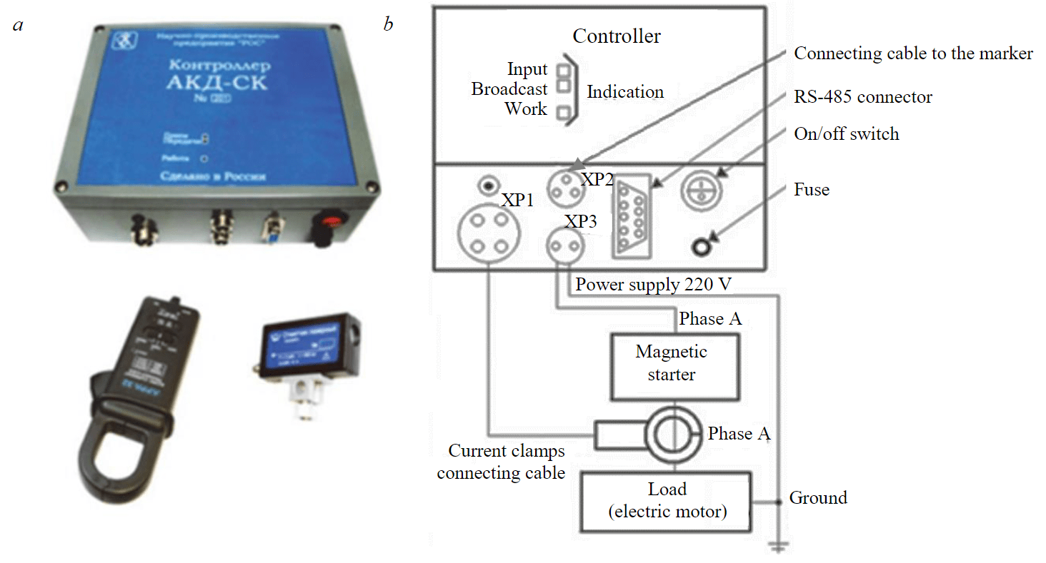
Fig.2. Software-registration complex “AKD-SK”: a – general view; b – block diagram
where n – number of measurement points for a fixed time interval ΔT; im – instantaneous value of the current at the m-th moment of time, A;
- effective voltage value
um – instantaneous value of the phase-to-phase voltage at the m-th moment of time, V.
Active Na (kW) and full power Sw (kVA) of the SRHP HD electric motor are calculated in accordance with the formulas:
The power factor is given by
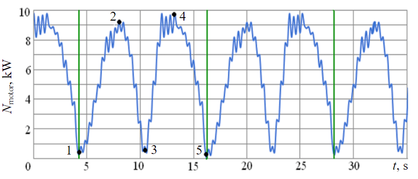
Fig.3. Wattmeter diagram of the balancing motor SK-8: lower (1, 5), horizontal (2, 4) and upper (3) crank position
Operational control data is stored in the instrument's non-volatile memory. At the request of the oil field engineering and technical specialists, they are transferred to the operator network. Using specialized software, the analysis and visualization of information obtained during monitoring is carried out.
As an example, Fig.3 shows a wattmeter diagram obtained during the operation of the motor of the balancing SK-8 [18]. The marker (green color) indicates the upper position of the SRSP, which corresponds to the lower position of the crank. Each movement cycle of the SK balancer head (one swing) is characterized by two power maxima, the difference between the values of which (for balanced SK) should not exceed 10 % [11].
The well flow rates, where the studies were carried out, was determined according to the data of verified measuring instruments equipped with verified measuring instruments. The research was carried out in two stages. First, the measurements were carried out on a well equipped with a SRHP with a SK-8 type mechanical drive. Then the SK was replaced by the HD and the same scope of tests was performed, which made it possible to correctly obtain a comparative assessment of the energy efficiency of the operation of the SRHP drives [19].
The average daily specific energy consumption for the well fluid production during the operation of the SRHP was calculated by the formula
where ΣWdayi – total energy costs for the operation of the SRHP for the i-th operation day, kWh; Qph.i – productivity of the SRHP for the i-th operation day, m3/day.
The average value of the specific energy consumption for the well fluid production during the operation of the SRHP for the t period was calculated by the formula
Comparative evaluation of the advanced SRHP hydraulic drives performance efficiency was carried out by determining the value of the drive energy efficiency coefficient in accordance with the formula
where Hw.b – specific energy consumption average value for the production of well fluid during the operation of SRHP equipped with a balancing SK (base value of specific energy consumption), kWh/m3; Hw.test – the specific energy consumption average value for the production of well fluid during the operation of the tested SRHP HD, kWh/m3.
A promising SRHP HD with pneumatic balancing was tested on Oblivskoye field well 109b. The program of comparative tests provided for the specific energy consumption determination for the reservoir fluid production during the operation of SRHP equipped with a SK-8 type mechanical drive and a NPK-10-8-6 hydraulic drive. Parameters of the tested SRHP are following: pump suspension depth L = 1534.9 m; stroke length S0 = 2.5 m; double strokes number n = 5.5 min–1. The specific energy consumption for lifting the well fluid when SRHP was equipped with a hydraulic drive NPK-10-8-6 was Hw.test = 25.6 kWh/m3, which is almost twice as high as on the balancing mechanical SK-8 (Hw.b = 12.8 kWh/m3), with the use of which the investigated well was operated earlier (Table 3). The value of the energy efficiency coefficient was ke.ef = 0.45.
Table 3
SRHP HD test results
|
Drive type |
Hydraulic drive NPK-10-8-6 |
SRHP HD 80-3.5 “Geyser” |
|||
|
SK-8 |
NPK-10-8-6 |
NPK-10-8-6 |
SK-8 |
SRHP HD 80-3.5 “Geyser” |
|
|
Used motors |
22 kW; 970 rpm |
15 kW; 1480 rpm |
15 kW; 1480 rpm |
22 kW; 970 rpm |
37 kW; 1480 rpm |
|
Operating parameters |
S0 = 2.5 m; n = 5.5 min–1 |
S0 = 2.5 m; n = 5.5 min–1 |
S0 = 5.0 m;n = 1.8 min–1 |
S0 = 2.5 m; n = 5.5 min–1 |
S0 = 2.5 m; n = 5.5 min–1 |
|
Measurement time, days |
9 |
7 |
42 |
6 |
5 |
|
Average daily energy consumption, kWh/day |
123.8 |
294.0 |
228.6 |
117.0 |
128.9 |
|
Average daily liquid flow rate, m3/day |
9.7 |
11.5 |
9.7 |
10.4 |
10.1 |
|
Specific energy consumption, kWh/m3 |
12.8 |
25.6 |
23.6 |
11.25 |
12.76 |
|
Energy efficiency ratio |
– |
0.45 |
0.54 |
– |
0.88 |
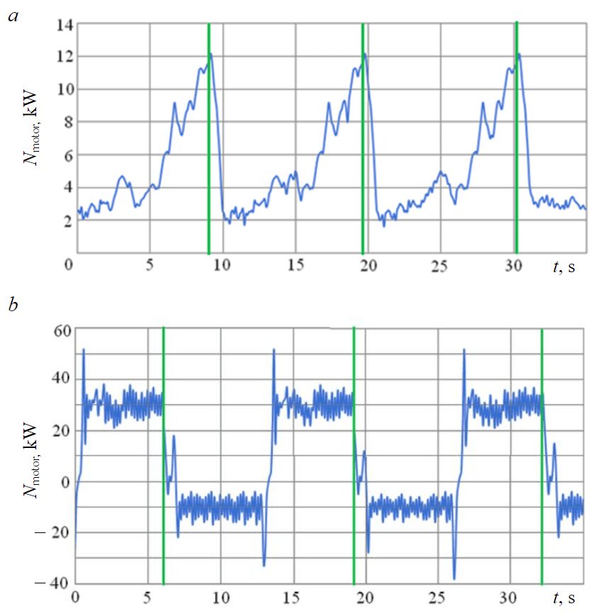
Fig.4. Drive motor power change: a – hydraulic drive pumping station NPK-10-8-6 with pneumatic balancing; b – pumping station station SRHP HD 80-3.5 “Geyser” with electrodynamic balancing [24]; SRSP top position is shown in green
The analysis of the wattmeter data obtained during the examination of a hydraulic drive with pneumatic balancing showed that in the given conditions, the maximum power value when lifting the SRSP is Nmotor = 12.1 kW, and when the rod is lowered Nmotor = 4.8 kW (Fig.4, a).
As the SRSP moves upwards, the loading of the drive motor increases, since the energy stored by the pneumatic accumulator is consumed (see Fig.1, c, pos.3). The insufficient volume of the latter causes the presence of pronounced peaks in the signal of the electric motor active power of the tested SRHP HD. The presence of asphalt-resin-paraffin deposits in the well has a significant effect on the load formation process: the pump rod string and the pump plunger move unevenly, periodically “hanging”, which causes the appearance of local peaks and power dips on the wattmeter diagram of the tested SRHP HD electric motor (Fig.4, a).
To reduce the specific energy consumption for oil production, a rod pump was replaced in the well. The stroke length of the SRHP rod was increased to S0 = 5.0 m, the number of double strokes was reduced to n = 1.8 min–1. A slight decrease in the specific energy consumption for the production of well fluid was noted (up to Hw.test = 23.6 kWh/m3). The energy efficiency coefficient increased to ke.ef = 0.54. High specific energy consumption and uneven loads during the operation of the SRHP HD NPK-10-8-6 are due to the imperfection of the chosen balancing method: the energy stored by the pneumatic accumulator during the reverse stroke of the SRSP is objectively not enough to significantly reduce the drive power during the working stroke.
Wide ranges of the HD operation mode parameters regulation allow them to be successfully used in complicated operating conditions of the SRHP. For example, in the trial operation course of a promising hydraulic drive NPK-10-8-6, a shutdown of the drive was recorded due to the sucker rod string hanging due to the formation of asphalt, resin, and paraffin deposits (ARPD) in the pumping and compressor pipeline [20-22]. Starting the drive in the well resuscitation mode (swing frequency and stroke length automatically change depending on the load in the SRSP) with a set number of oscillations n = 1 min–1 and a rod stroke S0 = 0.5 m, together with the hot oil supply to the annulus, made it possible rinse the ARPD. After 2 h of drive operation in the specified mode, the stroke of the rod increased to the set value S0 = 2.5 m, after 3 h the load in the SRSP returned to normal, the operation of the SRHP was returned to the nominal mode without current workover of the well [15].
Comparative tests of SRHP equipped with a mechanical drive with SK-8 balancing pumping unit and a hydraulic drive with electrodynamic balancing SRHP HD 80-3.5 “Geyser” were carried out at Sosnovskoye oil field well 404. A distinctive feature of the scheme of this hydraulic drive is the presence of an intelligent electronic control system (IECS) unit for the oil station drive motor (see Fig.1, d, pos. 7, 8), which includes a frequency converter and an inverter [23].
During the tests, the well was operated with the following SRHP parameters: pump suspension depth L = 1560.1 m; stroke length S0 = 2.5 m; the number of double strokes n = 5 min–1 (Table 3). The specific energy consumption for lifting the well fluid during the operation of the SRHP equipped with the hydraulic drive SRHP HD 80-3.5 “Geyser” was Hw.test = 12.76 kWh/m3, which is slightly higher than the values of specific energy consumption obtained from measurements on mechanical SK-8 drive (Hw.b = 11.25 kWh/m3), with which this well was previously operated. On the wattmeter diagram of the motor of the pumping station SRHP HD 80-3.5 “Geyser” (Fig.4, b), it is possible to distinguish sections of the working and reverse stroke of the power hydraulic cylinder rod [24].
During the working stroke, the HP pumping station motor with electrodynamic balancing works with a rated load, the power factor is cosφ = 0.85. When the power hydraulic cylinder rod is lowered, the motor SRHP HD 80-3.5 “Geyser” recuperates 25-29 % of energy into the oil field network, which corresponds to the results of similar studies [7].
The energy recuperated into the oil field network of the IECS of the SRHP HD 80-3.5 “Geyser” pumping station is characterized by the presence of higher harmonics in the current and voltage signals, which is due to the frequency converter operation. Voltage waveform distortion negatively affects the work of electricity consumers: the efficiency of the generation processes, transmission, and use of energy in the oil field network is reduced; electrical equipment insulation aging occurs; the losses in the windings of electrical machines increase [15, 25, 26].
Results discussion
Both tested SRHP HD showed lower energy efficiency compared to traditional mechanical drives SK-8. A common disadvantage of SRHP HD with pneumatic balancing is the use of two working agents – gas and liquid, which necessitates the use of two separate leakage compensation systems. In most SRHP HD models with pneumatic balancing, the frequency of double strokes of the power hydraulic cylinder rod is regulated by increasing the pause between strokes due to the lower reliability of variable pumps compared to the pumps with a constant supply. This significantly reduces the energy efficiency of the considered hydraulic drives. Nevertheless, a number of manufacturers continue to produce and sell SRHP drives with pneumatic balancing on the market, since satisfactory adjusting characteristics and lower metal consumption compared to mechanical SK allow the described SRHP HD to be successfully used in complicated operating conditions of downhole equipment.
The advantage of SRHP HD with dynamic and electrodynamic balancing is the hydraulic part design simplicity. The open type of hydraulic transmission does not provide for the use of additional equipment to compensate for leaks. The regulation of operating parameters is carried out by using a frequency drive, which allows using volumetric constant flow motor-pumps in the design.
Significant shortcomings of the considered drives should be noted. The process of energy recovery during the operation of the IECS causes an increase of the reactive power in the oil field network and the harmonic interference (parasitic EMF) appearance, which negatively affects the work of consumers [7, 27, 28]. Power balance correction in the field network is provided by installing expensive compensating devices, which increases the operating costs for the maintenance of well equipment [29].
Elimination of this disadvantage is possible when using electricity consumers switching circuit as part of the SRHP HD with electrodynamic balancing, which ensures the accumulation and use of recuperated electricity for the operation of auxiliary consumers and peripheral devices SRHP (Fig.5).
The essence of the technical solution developed by the authors is as follows. The reverse relays of the power hydraulic cylinder and the electric power accumulator are installed in the consumer circuit of the SRHP HD under consideration. When lifting the power hydraulic cylinder rod and SRSP, the voltage from the power grid is supplied to the frequency converter (FC) and then to the electric motor M1 of the hydraulic drive pumping station. By means of the frequency converter, the speed of the M1 motor rotor and the supply of the hydraulic drive pump are controlled, which makes it possible to change the stroke rate of the SRSP (n). The relay K of the hydraulic cylinder (HC) reverse run is de-energized, and its closed contact K.2 supplies a control signal to close the automatic battery power switch directly from the network.
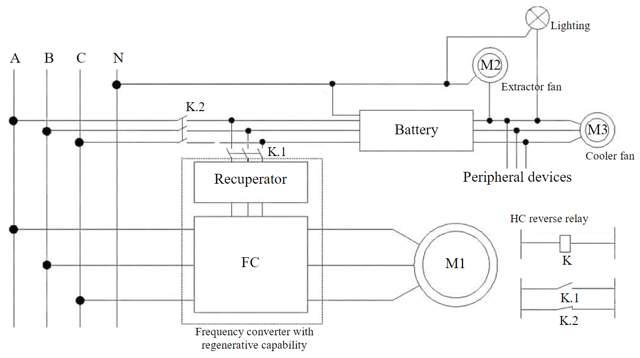
Fig.5. Switching scheme of electric power consumers as a part of SRHP hydraulic drives with electrodynamic balancing
When lowering the SRSP, the working fluid from the power hydraulic cylinder rod end is supplied to the pump, which operates as a hydraulic motor, spinning the M1 motor rotor. Motor M1 operates in generator mode. The generated electricity through the heat exchanger and the closed-circuit breaker, controlled by contact K.1 of the hydraulic cylinder reverse stroke relay K, is fed to the battery and then, as necessary, is consumed during the operation of the auxiliary consumers of the hydraulic drive. The motor M2 of the exhaust fan in the drive block box or the motor M3 of the working fluid cooler fan (radiator), and lighting devices can act as such. Various connection schemes and the use of electrical equipment allow you to supply receivers of different types and voltages.
Electricity from the battery can be spent on the operation of SRHP peripherals: rod rotators, local heating devices, dosing units for reagents, etc. The described technical solution ensures the efficient use of the generated and stored energy during the operation of the SRHP HD with electrodynamic balancing.
From the point of view of the analysis of the kinematic parameters of the movement of the SRSP and the loads on the electric motor, the examined hydraulic drive “Geyser” should be considered as unbalanced. These drives require high power motors. Significant dynamic loads cause an accelerated consumption of the drives resource with electrodynamic balancing, which determines the increase in operating costs for their maintenance in working condition.
A common disadvantage of SRHP HD with the dynamic balancing is a change in the direction of counter torque from an external load on the motor-pumps shafts and drive electric motors. Since these parts, as a rule, have small cross-sectional dimensions and are mated with the rest of the drive units by means of spline connections, they are characterized by frequent failures associated with metal fatigue and the destruction of splines. Over 41 % of the failures of the SRHP HD hydraulic part with dynamic balancing occur due to the failure of the axial piston pumps of the hydraulic power transmission. This negative phenomenon is typical for drives with electrodynamic balancing and for SRHP HD with the inertial type of balancing.
An analysis of the theoretical and experimental studies results shows that the use of electrodynamic and pneumatic methods of balancing the SRHP HD negatively affects the energy efficiency and reliability of the operation of the pumping unit as a whole. The load balancing devices are characterized by maximum efficiency and durability (see Table 2).
In SRHP HD with load balancing, a load is used as an energy accumulator of the balancing device. The advantage of such drives is the design simplicity and reliability. At the same time, these HDs are characterized by increased metal consumption, comparable to SRHP hydraulic drives with pneumatic balancing, and worse mounting ability.
The authors proposed and patented the scheme of the SRHP HD with a load balancing (Fig.6). The drive consists of a power hydraulic cylinder 1 and a balancing load-hydraulic accumulator 2 (it is a vertically mounted hydraulic cylinder with weights fixed on the rod), the rod cavities of which are connected by a pipeline 3 as communicating vessels. The pipeline 3 through the check valve 4 is connected to the high-pressure cavity 5 of the intermediate double-sided cylinder 6. The pump 7 supplies the working fluid from the oil tank 8 to the piston cavities of the power hydraulic cylinder 1 and the hydraulic load accumulator 2 through the hydraulic distributor 9. The working fluid is cleaned by the filter 10. Pump protection 7 overload protection is implemented by a safety valve 11.
The working fluid pumping into the cavity of low pressure 12 and high pressure 5 of the intermediate double-sided cylinder 6 is carried out by the pump 7 through the hydraulic distributor 13. The working fluid is drained from the rod cavities of the power hydraulic cylinder 1 and the load-hydraulic accumulator 2 through a two-position hydraulic distributor 14 through an adjustable throttle 15. Working pressure in the hydraulic system is controlled by manometers (pressure sensors) 16-18. The number of swings and stroke of the power hydraulic cylinder 1 are determined by the readings of sensors 19, the signals from which are transmitted to the intelligent control unit (ICU) 20. In the drain line of SRHP HD, the fluid flow is switched by the distributor 21 to the controlled throttle 22 for damping loads on the final sections of the SRSP movement.
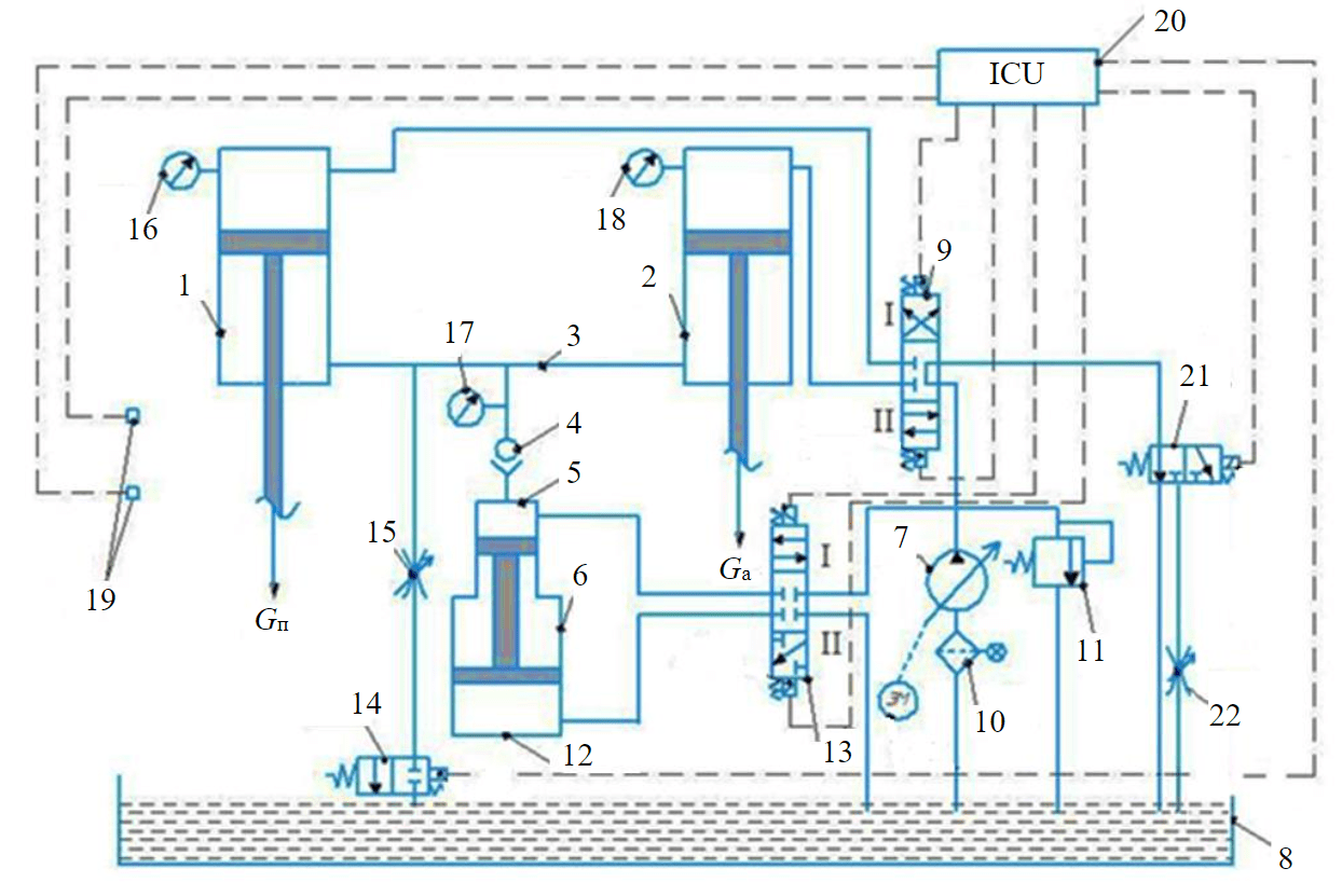
Fig.6. Hydraulic scheme of advanced SRHP drive with load balancing
After filling the hydraulic system with a working fluid and installing the described SRHP HD above the wellhead, its work is carried out as follows. The power hydraulic cylinder rod 1 is connected to the pump rod string and the downhole pump plunger. The lifting of the power cylinder rod 1 is carried out by pumping the working fluid by the pump 7 from the tank 8 into the piston cavity of the hydraulic load accumulator 2 when the hydraulic distributor 9 is switched to position II. At the same time, in the SRSP, a load Gp occurs on the rod of the power hydraulic cylinder 1, balanced by the weight of the loads Gа, fixed on the rod of the hydraulic load accumulator 2. The weight of the balancer with the same design parameters of the power hydraulic cylinder and the balancing hydraulic cylinder of the hydraulic load accumulator is calculated by the formula
where Grod – sucker rod string weight in liquid, kN; Gliq – liquid column weight, kN [11].
The working fluid from the piston cavity of the power hydraulic cylinder 1 through the distributor 9 is fed into the drain line by means of a two-position distributor 21, which, at the SRHP movement final stage, switches the fluid flow to the throttle 22, braking the power hydraulic cylinder 1 piston.
The signal from the ICU 20 to the magnetic coil of the hydraulic distributor 9 ensures that the latter is switched to position I. The working fluid from the tank 8 is supplied by an adjustable pump 7 to the piston cavity of the power hydraulic cylinder 1, the reverse stroke of the SRHP and the plunger of the borehole pump is carried out. In this case, the working fluid from the rod cavity of the power hydraulic cylinder 1 is displaced into the rod cavity of the balancing hydraulic cylinder of the load-hydraulic accumulator 2. The loads weighting Ga, fixed on the rod of the load-hydraulic accumulator 2, rise, and energy is accumulated to balance the SRHP HD. From the hydraulic load accumulator cylinder 2 piston cavity, the liquid is drained through the hydraulic distributors 9 and 21 into the oil tank 8.
If it is necessary to reduce the power hydraulic cylinder 1 stroke, a working fluid partial discharge from the pipeline 3 is realized through the adjustable throttle 15 and the two-position hydraulic valve 14 into the oil tank 8. The working fluid injection into the rod cavities of the power cylinder 1 and balancing hydraulic cylinder 2 to increase the stroke length of the SRSP is carried out through the pipeline 3 by the intermediate double-sided hydraulic cylinder 6. The process is implemented as follows. ICU 20 sends a signal to the control coil of the hydraulic distributor 13 and switches it to position I. The working fluid is pumped by the pump 7 into the high-pressure cavity 5 of the intermediate double-sided hydraulic cylinder 6, while the liquid is forced out of the low-pressure cavity 12 into the oil tank 8.
After cavity 5 is filled, the hydraulic valve 13 switches to position II at the ICU 20 signal, the low-pressure cavity 12 of the intermediate double-sided hydraulic cylinder 6 is filled with working fluid from the oil tank 8, from the high-pressure cavity 5, the working fluid is displaced through the check valve 4 into the pipeline 3. Operation of the intermediate hydraulic cylinder 6 and the hydraulic distributor 13 is carried out until the rod cavities of the power 1 and balancing 2 hydraulic cylinders are filled with a given volume of working fluid, which ensures the required amount of movement of the SRSP, its actual value is determined by the readings of sensors 19. Change in the amount of return-but-translational movements of the rod of the power hydraulic cylinder 1 per unit time is carried out by regulating the supply of the positive displacement pump 7.
The application of the described scheme and operation algorithm ensures the balancing of the SRHP HD and its energy efficient operation in the oil field [30]. The proposed HD scheme simplicity and the dynamic loads minimization on the drive elements will increase the time between failures of the entire SRHP, which will positively affect the profitability of the oil production process [31-33]. A distinctive feature of the SRHP HD circuit is the absence of a make-up pump: leakage compensation and the supply of working fluid to the rod cavities of the power hydraulic cylinder and the balancing load hydraulic accumulator are carried out by means of an intermediate double-sided hydraulic cylinder, which simplifies the drive design.
The assessment of the economic efficiency of the load-balancing HD implementation can be carried out by comparing the net present value NPV in the operation of oil wells with SRHP, equipped with traditional SK mechanical drives and the proposed HD [34, 35]. Factors influencing the assessment of economic efficiency are presented in Table 4.
The peculiarity of the projects comparison is that the drives service life is different: the average service life of the SRHP HD is 1.5-2 times less than that of the SK mechanical drive. To compare projects at different times, you can apply the method of chain repetition: determine the smallest multiple of the terms of projects and compare the sums of their net present value [36].
Table 4
Assessment of economic efficiency when replacing the SRHP mechanical drive with a hydraulic one
|
Factors leading to an increase in net present value |
Factors leading to a decrease in net present value |
|
Reduction of unit costs for electricity |
Increase in the number of repairs and maintenance of the drive |
|
Reduced drive installation costs (there is no need for massive foundations, as for mechanical SKs) |
Increase in the cost of purchasing spare parts during repair and restoration work (hydraulic and electrical parts of drives) |
|
Reducing the number of ongoing well repairs |
Reducing the service life by 1.5-2 times compared to mechanical SK |
It is assumed that the sales proceeds will be the same for the compared projects, since the performance of the SRHP does not differ. The change in net present value ΔNPVΣ is to reduce operating costs, change the income tax, the difference in capital investments, and the amount of depreciation. Thus, the change in the net present value when replacing the traditional SRHP mechanical drive with a promising hydraulic drive is generally determined by the expression
where P – project implementation period, years; ΔOt – change in operating costs for period t, rub.; ΔTt – change of the income tax for the period t, rub.; ΔCt – difference in capital investments for period t, rub.; ΔAt – difference in depreciation for the period t, rub.; r – discount rate adopted for project evaluation, unit share.
The reduction in operating costs will be achieved by reducing the unit cost of electricity and the cost of ongoing well workovers [37]. It should be taken into account that the use of HD with load balancing entails an increase in the number of repairs, maintenance of the drive and the purchase of spare parts during repair and restoration work (hydraulic and electrical parts of drives) [38]. The formula for calculating the reduction in operating costs from the implementation of the SRHP HD scheme with load balancing can be represented as
where ∆Oel.en – operating costs reduction for electricity for the production of well fluid, rub.; ∆Owo – reduction of operating costs for current workovers, rub.; ∆Omt – additional operating costs associated with an increase in the number of repairs and maintenance of drives, rub.; ∆A – difference in depreciation, rub.
To calculate the savings in energy costs for the production of well fluids, data are needed on the average daily electricity consumption during the operation of the SRHP HD with load balancing and the average daily flow rate of the well fluid. In further studies, it is planned to create an industrial design of SRHP HD and conduct the test of the proposed drive, during which the necessary data will be obtained.
Conclusion
SRHP HD design and operation features show the prospects for their further improvement and widespread implementation in the oil fields of Russia and the CIS countries in the complicated and marginal oil wells operation. The described approaches, methodology and equipment for conducting experimental studies make it possible to perform a comparative assessment of the effectiveness of the functioning of mechanical and hydraulic drives of SRHPs in terms of the energy efficiency coefficient.
Introduction of SRHP HD with the electrodynamic balancing of power accumulators into the switching circuits allows accumulating and using recuperated electric power for operation of the auxiliary consumers and peripheral devices of SRHP. Minimization of reactive power and parasitic EMF in oilfield networks is provided. A promising scheme of the SRHP HD with load balancing is proposed, which provides the possibility of effective balancing of the drive and reducing the dynamic loading of its power elements.
References
- Ivanovskii V.N. Increasing interest in sucker rod pumping units – what is the reason? Territoriya NEFTEGAZ. 2013. N 8, p. 46-47 (in Russian).
- Myrzakhmetov B.A., Nurkas Zh.B., Sultabaev A.E. Protection of downhole pumping equipment in case of high sand production. Gornyi zhurnal. 2022. N 7, p. 82-86 (in Russian). DOI: 10.17580/gzh.2022.07.14
- Bealessio B.A., Blánquez Alonso N.A., Mendes N.J. et al. A review of enhanced oil recovery (EOR) methods applied in Kazakhstan. Petroleum. 2021. Vol. 7. Iss. 1, p. 1-9. DOI: 10.1016/j.petlm.2020.03.003
- Lavrenko S., Klushnik I., Iarmolenko V. Test results for hydraulic drives of sucker-rod pumping units. ARPN Journal of Engineering and Applied Sciences. 2019. Vol. 14. N 16, p. 2881-2885.
- Grigorev S.L., Demidov O.V. Rod pump hydraulic drive – a new oil production technology. Territoriya NEFTEGAZ. 2010. N 10, p. 59 (in Russian).
- Xinmin Song, Debin Qu, Cunyou Zou. Low cost development strategy for oilfields in China under low oil prices. Petroleum Exploration and Development. 2021. Vol. 48. Iss. 4, p. 1007-1018. DOI: 10.1016/S1876-3804(21)60085-X
- Drozdov A.N., Blokhin S.A., Pak D.X. et al. Analysis of the efficiency of the hydralic drive “Geron” application as an alternative to the usage of standart pumpjack. Trudy nauchno-prakticheskoi konferentsii s mezhdunarodnym uchastiem “Inzhenernye sistemy – 2019”, 3-5 April 2019, Moscow, Russian Federation. Moscow: Peoples’ Friendship University of Russia. 2019, p. 360-366 (in Russian).
- Fei Yao, Yu-xue Sun, Dekui Xu et al. Research Status and Development Trend of Clean Operation Technology in Domestic Onshore Oilfield. Proceedings of the International Field Exploration and Development Conference 2020. Singapore: Springer, 2021, p. 2331-2342. DOI: 10.1007/978-981-16-0761-5_220
- Youhong Sun, Yuanling Shi, Qingyan Wang, Zongwei Yao. Study on speed characteristics of hydraulic top drive under fluctuating load. Journal of Petroleum Science and Engineering. 2018. Vol. 167, p. 277-286. DOI: 10.1016/j.petrol.2018.04.003
- Abebe A., Tadesse Y., Beyene A. Conversion of Thermally Amplified Hydraulic Shock for Power Generation: Modeling and Experimental Analyses. Journal of Energy Resources Technology. 2023. Vol. 145. Iss. 2. N 022103. DOI: 10.1115/1.4054826
- Molchanov A.G. Scientific basis for the design and operation of hydraulically driven sucker-rod pumping units for oil production: Avtoref. dis. ... d-ra tekhn. nauk. M.: Gosudarstvennaya akademiya nefti i gaza im. I.M.Gubkina, 1998, p. 34 (in Russian).
- Sidorkin D.I., Kupavykh K.S. Justification on choosing screw pumping units as energy efficient artificial lift technology. Energetika. Proceedings of CIS Higher Education Institutions and Power Engineering Associations. 2021. Vol. 64. N 2, p. 143-151. DOI: 10.21122/1029-7448-2021-64-2-143-151
- Urazakov K.R., Molchanova V.A., Tugunov P.M. Method for calculating dynamic loads and energy consumption of a sucker rod installation with an automatic balancing system. Journal of Mining Institute. 2020. Vol. 246, p. 640-649. DOI: 10.31897/PMI.2020.6.6
- Nickell I., Treiberg T. Autonomous Control of Well Downtime to Optimize Production and Cycling in Sucker Rod Pump Artificially Lifted Wells. SPE Artificial Lift Conference and Exhibition – Americas, 23-25 August 2022, Galveston, USA. OnePetro, 2022. N SPE-209743-MS. DOI: 10.2118/209743-MS
- Ustinov A.N., Tyaktev M.V., Shishlyannikov D.I. et al. Increasing the efficiency of hydraulic drives of sucker-hole pumping units for oil production. Mining Equipment and Electromechanics. 2017. N 7 (134), p. 26-31 (in Russian).
- Eisner P., Langbauer C., Fruhwirth R.K. Comparison of a novel finite element method for sucker rod pump downhole dynamometer card determination based on real world dynamometer cards. Upstream Oil and Gas Technology. 2022. Vol. 9. N 100078. DOI: 10.1016/j.upstre.2022.100078
- Kunshin A., Dvoynikov M., Timashev E., Starikov V. Development of Monitoring and Forecasting Technology Energy Efficiency of Well Drilling Using Mechanical Specific Energy. Energies. 2022. Vol. 15. Iss. 19. N 7408. DOI: 10.3390/en15197408
- Moreno G.A., Garriz A.E. Sucker rod string dynamics in deviated wells. Journal of Petroleum Science and Engineering. 2020. Vol. 184. N 106534. DOI: 10.1016/j.petrol.2019.106534
- Teplyakova A.V., Azimov A.M., Alieva L., Zhukov I.A. Improvement of manufacturability and endurance of percussion drill assemblies: Review and analysis of engineering solutions. Mining Informational and Analytical Bulletin. 2022. N 9, p. 120-132 (in Russian). DOI: 10.25018/0236_1493_2022_9_0_120
- Shuqiang Wang, Shimin Dong, Xuelin Yu. Transverse vibration simulation of sucker rod string under normally distributed load caused by viscoelastic fluid in a curved wellbore. Journal of Sound and Vibration. 2022. Vol. 536. N 117181. DOI: 10.1016/j.jsv.2022.117181
- Dong Shimin, Wang Hongbo. Simulation model of lateral vibration of sucker rod string in directional wells and point arrangement optimization of centralizer. Acta Petrolei Sinica. 2020. Vol. 41. Iss. 12, p. 1686-1696. DOI: 10.7623/syxb202012021
- Wang Hong-bo, Dong Shi-min. A model for the transverse vibration simulation of sucker rod strings with axial reciprocating motion in curved wellbores. Engineering Mechanics. 2020. Vol. 37. N 10, p. 228-237. DOI: 10.6052/j.issn.1000-4750.2019.12.0731
- Omirbekova Z., Aktaukenov D., Amangeldiyev A., Abdallah A. Developing Predictive Oil Well Diagnostics Based on Intelligent Algorithms. IEEE International Conference on Smart Information Systems and Technologies, 28-30 April 2021, Nur-Sultan, Kazakhstan. IEEE, 2021, p. 1-7. DOI: 10.1109/SIST50301.2021.9465959
- Shishlyannikov D.I., Tyaktev M.M., Ivanchenko A.A. et al. Assessment of hydraulic drives loading of sucker rod downhole pumping units. Construction of oil and gas wells on land and sea. 2019. N 4, p. 34-39 (in Russian). DOI: 10.30713/0130-3872-2019-4-34-39
- Ruichao Zhang, Yuqiong Yin, Liangfei Xiao, Dechun Chen. A real-time diagnosis method of reservoir-wellbore-surface conditions in sucker-rod pump wells based on multidata combination analysis. Journal of Petroleum Science and Engineering. 2021. Vol. 198. N 108254. DOI: 10.1016/j.petrol.2020.108254
- Takács G. A critical analysis of power conditions in sucker-rod pumping systems. Journal of Petroleum Science and Engineering. 2022. Vol. 210. N 110061. DOI: 10.1016/j.petrol.2021.110061
- Savinkin V.V., Sandu A.V., Ratushnaya T.Yu. et al. Study of redistribution of the oil complex power drive effectiveness for marginal wells when installing construction of recuperative action electro hydro cylinder. Bulletin of the Tomsk Polytechnic University. Geo Аssets Engineering. 2021. Vol. 332. N 2, p. 229-244 (in Russian). DOI: 10.18799/24131830/2021/2/3058
- Skamyin A., Shklyarskiy Ya., Dobush I. et al. An assessment of the share contributions of distortion sources for various load parameters. International Journal of Power Electronics and Drive Systems. 2022. Vol. 13. N 2, p. 950-959. DOI: 10.11591/ijpeds.v13.i2.pp950-959
- Shklyarskiy Ya., Skamyin A., Vladimirov I., Gazizov F. Distortion Load Identification Based on the Application of Compensating Devices. Energies. 2020. Vol. 13. Iss. 6. N 1430. DOI: 10.3390/en13061430
- Litvinenko V.S., Sergeev I.B. Innovations as a Factor in the Development of the Natural Resources Sector. Studies on Russian Economic Development. 2019. Vol. 30. N 6, p. 637-645. DOI: 10.1134/S107570071906011X
- D.I.Shishlyannikov, A.A.Ivanchenko, S.A.Frolov, V.Yu.Zverev, A.V.Nikolaev. Patent N 2779011 RF. Rod pump hydraulic drive. Publ. 30.08.2022. Bul. N 25.
- Isaev A.A., Aliev M.M.O., Drozdov A.N. et al. Improving the Efficiency of Curved Wells’ Operation by Means of Progressive Cavity Pumps. Energies. 2022. Vol. 15. Iss. 12. N 4259. DOI: 10.3390/en15124259
- Cherepovitsyn A., Rutenko E. Strategic Planning of Oil and Gas Companies: The Decarbonization Transition. Energies. 2022. Vol. 15. Iss. 17. N 6163. DOI: 10.3390/en15176163
- Ponomarenko T., Marin E., Galevskiy S. Economic Evaluation of Oil and Gas Projects: Justification of Engineering Solutions in the Implementation of Field Development Projects. Energies. 2022. Vol. 15. Iss. 9. N 3103. DOI: 10.3390/en15093103
- Tarabarinova T.A., Golovina E.I. Capitalization of mineral resources as an innovation ecological strategy. Geology and Mineral Resources of Siberia. 2021. N 4 (48), p. 86-96 (in Russian). DOI: 10.20403/2078-0575-2021-4-86-96
- Yashin S.N., Trifonov Yu.V., Koshelev E.V. Comparison of Replacement Chain and Equivalent Annual Annuity Approaches to Evaluate Technological Innovation of the Company. Financial Analytics: Science and Experience. 2018. Vol. 11. Iss. 1, p. 32-42 (in Russian). DOI: 10.24891/fa.11.1.32
- Ruidong Zhao, Jinya Li, Zhen Tao et al. Research and Application of Rod/Tubing Wearing Prediction and Anti-Wear Method in Sucker Rod Pumping Wells. SPE Middle East Oil and Gas Show and Conference, 18-21 March 2019, Manama, Bahrain. OnePetro, 2019. N SPE-194955-MS. DOI: 10.2118/194955-MS
- Aliyev E.A., Gabibov I.A., Ismailova R.A., Huseynov R.O. Application of new repair technology in the restoration of plungers of borehole rod pumps. SOCAR Proceedings. 2022. N SI2, p. 1-4 (in Russian). DOI: 10.5510/OGP2022SI200730