Evaluation of the shear strength of rocks by cracks based on the results of testing samples with spherical indentors
- 1 — Ph.D. Leading Researcher Saint Petersburg Mining University ▪ Orcid
- 2 — Ph.D. Head of Laboratory Saint Petersburg Mining University ▪ Orcid
- 3 — Engineer Saint Petersburg Mining University ▪ Orcid

Abstract
Experimental data on the relationship of the residual shear strength of rocks in closed cracks with the functional characteristics of intact rocks – the tensile and compressive components of adhesion, the roughness of the crack surfaces, and the level of normal stresses are presented. A unified integrated approach determines the shear strength of intact and destroyed rocks, the residual shear strength of closed rough cracks has been developed. The approach provides for the selection of stress intervals corresponding to different types of fracture, for each of which a strength criterion is proposed, expressed in terms of functional characteristics of intact rock. An express method for estimating the residual shear strength of rocks by cracks with a rough surface has been developed, in which an improved method of loading samples with spherical indentors is used as a basic test method. The express method implements the transition from the data of mechanical tests of samples with spherical indentors to the shear strength indicators for cracks in the rock mass, taking into account the level of normal stresses and the roughness of the crack surfaces measured in field conditions. In this case the roughness scale developed by Barton is used. The express method is informative and available in the fieldwork.
None
Introduction
The destruction of rocks in the masses during the operation of the deposit occurs in the conditions of an inhomogeneous stress state in the mode of stress redistribution during mining operations and has a probabilistic character [1, 2]. So, for geomechanical similarity to the processes encountered in mining practice [3, 4], during laboratory mechanical tests of rocks and its weakening surfaces (cracks), special attention should be paid to the representativeness of tests with respect to the type of stress state and the mechanism of destruction characteristic of real conditions in the rock masses. These requirements are met by methods of splitting samples with concentrated loads [5] – the method of loading samples with spherical indentors [6] and its analogue point-load strength test [7]. These test methods implement a complex mechanism of sample destruction, including local destruction of intact rock by separation and cut, as well as deformation of the destroyed rock at high compressive stresses. Taking into account the technical simplicity and accessibility for mass use, the improved method of loading samples with spherical indenters is used as a basic test method for simplified evaluation of the parameters of the certificate of the ultimate and residual strength of the rock [8, 9].
The rock mass is characterized by a significant difference in the strength properties of the composing rocks and the weakening surfaces (cracks) [10-12]. The shear resistance of cracks in a rock mass is more often estimated based the laboratory tests of small-sized samples on closed cracks and the description of natural cracks in the field [13-15]. In practice to describe natural cracks, both the scale of standard roughness profiles developed by Barton [16] and the roughness assessment in the first approximation, based on the selection of smooth, wavy or stepped morphological types of closed cracks according to the Russian classification, are used [17]. At the same time, the determination of shear strength (SS) by cracks in laboratory conditions is often complicated by the lack of the required sample amount, the spread of crack characteristics, the discrepancy between the geometric dimensions of cracks and their roughness parameters in the sample and rock mass. In addition, damages to the surfaces of natural cracks during sampling and preparation for testing samples further distort experimental data. Due to the complexity of sampling representative samples, it is relevant to develop accelerated methods available in the field for determining the shear strength of rocks by cracks according to technically simple tests of small-sized samples.
The results of studies aimed at developing a new approach to assessing the shear strength of rocks by cracks based on the test data of intact samples with spherical indentors are presented. The approach takes into account the stress level and the roughness of cracks in real conditions and is designed to obtain initial data on the SS of the rock mass on the weakening surfaces.
Methods
To assess the ultimate stress state of a fractured rock mass as an empirical criterion of failure, data on the construction of the envelope of the limiting circles of Mohr stresses (strength certificates) are widely used. At the same time, the shear strength of a rock mass is usually estimated based on determining the properties of intact rocks and an integral assessment of the influence of weakening surfaces (cracks) on these rocks [18-20].
The same rocks in different stress states can break down brittle and deform plastically [21, 22]. At the same time, the transition from one type of destruction to another with a change in the stress state occurs gradually [23], with a certain probability of its implementation [24]. In the Mohr diagram, it is manifested in the fact that the shear strength of rock samples, both intact and destroyed by triaxial compression or weakened by cracks, is characterized by envelopes of limiting stress circles similar in shape [16, 23]. The envelope strength curves of both intact and structurally weakened rock during the transition from the interval of tensile stresses to the interval of compressive stresses flatten out and tend to merge at a high stress level [25, 26].
The construction of Mohr stress envelopes corresponding to the ultimate and residual strength of rocks, according to laboratory tests of cylindrical samples, is associated with numerous tests in a wide range of stresses on complex equipment. Given the complexity and difficulty of this approach, simplified computational methods for constructing envelopes of ultimate and residual strength based on empirical dependences of shear strength on normal stresses, taking into account the characteristics of specific rocks, have become widespread [25, 27, 28]. As the main parameters of empirical dependencies (fracture criteria), the values of mechanical indicators characterizing various types of destruction (shear and separation) are usually used, and which are determined by technically simple and accessible methods [29, 30]. Two approaches to the presentation of empirical dependencies (fracture criteria) are most common.
The first approach is to use mathematical formulas describing a single dependence for the entire range of possible values of normal stresses [16, 29, 31]. The disadvantage of such empirical fracture criteria is usually the limited scope of their application by the characteristics of specific rocks, the type of fracture or the stress range [32]. For example, a computational method for constructing a strength certificate based on the data of determining the strength limits for uniaxial compression and tension (GOST 21153.8) it is not recommended to use in the range of normal stresses exceeding the values of 1.5 of the strength limit for uniaxial compression.
The second (complex) approach provides for conditional selection of normal stress intervals corresponding to different types of destruction, for each of which a separate strength criterion is proposed. When constructing dependencies in the selected stress intervals, preference is given to simple empirical formulas. For example, when describing the shear strength of a rough crack in accordance with the Patton criterion and when determining the ultimate and residual strength of rocks under triaxial compression in accordance with the ISRM standard, a bilinear approximation of the limiting envelopes is used. In addition, in accordance with the modified Mohr – Coulomb strength criterion, a circular arc [30] replaces the rectilinear limiting envelope in the interval of tensile stresses.
The shear resistance of cracks of various types in sedimentary, igneous and metamorphic rocks can be described by general dependencies that take into account the inclination angles of surface irregularities for closed cracks, the strength properties of crack walls and the level of normal stresses. At the same time, the shear resistance differs significantly for cracks of smooth, wavy and stepped morphological types [33-35]. With this in mind, a nonlinear empirical SS criterion for cracks in a rock mass (the Barton – Bandis criterion) is proposed, which takes into account the roughness and strength of the rock walls of cracks [36]:
where σn – effective normal stress; JRC – crack roughness coefficient, varies from 0° for smooth sliding surfaces to 20° for stepped rough surfaces; JCS – compressive strength of the crack surface; φr – residual friction angle (about 30°).
The empirical Barton – Bandis formula allows to take into account the peculiarities of changing the parameters of the ultimate strength envelopes for cracks in the rock mass. Analysis of this approach has shown that at normal stress σn, exceeding the crack surface strength JCS, or low stress σn, corresponding to the value of the friction angle of more than 70°, the equation (1) stops working. Considering this, it was noted in [37] that the Barton – Bandis criterion should be used with caution when designing the walls of open pits. A large number of studies aimed at improving this criterion have been published [38-40].
A similar comprehensive approach is proposed for constructing a rock strength certificate based on the results of tests for splitting samples with spherical indentors by an improved method developed at Saint Petersburg Mining University [41, 42]. The essence of this test method consists in axial compression of the sample by two spherical indentors, fixation of the destructive power P and measurement in the destroyed sample of the separation surface area S and the zones of the rock destroyed by the cut near the indentors F1 and F2, of which the larger F is taken into account (Fig.1, а). Thus, within the framework of the known approach, a significant refinement is proposed – in addition to determining the tensile component of the stresses σt in the sample, the compressive component of the stresses p is additionally estimated for local destruction by a cut. This makes it possible, in contrast to the standard test method (GOST 24941), to take into account the complex nature of the sample destruction, including deformation of the destroyed rock at contacts with indentors and destruction of the rock by separation and cutting at the boundary of the destroyed zones.
When calculating the parameters of the strength certificate, the tensile and compressive components of the ultimate shear resistance (adhesion) are taken as functional characteristics that determine the rock destruction:
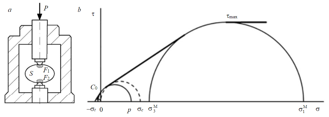
Fig.1. Construction of a strength certificate of an intact rock sample [5]: a – scheme of testing the sample with spherical indentors; b – construction of a strength certificate of the sample in the Mohr coordinate system
For the convenience of calculations, formulas can be expressed using the brittleness coefficient K (K = p/st) or the brittleness coefficient Kf equal to the ratio of the strength limits under uniaxial compression and tension (Kf = σc/sT). At the same time, the relation of σt and p with the strength limits is established:
In the Mohr diagram, the envelope of the rock stress limit circles was approximated by a complex of interrelated segments: rectilinear segments corresponding to stable types of macrofracture (separation, cut, and quasi – plastic deformation), and circular arcs of the Mohr stress limit circles, for which the type of fracture is probabilistic (Fig.1, b). In this case the coupling C0, which was approximated by a segment of the Mohr circle arc {–σt; p} in the range of normal stresses from 0 to (p – σt)/2, corresponded to the probabilistic fracture by separation or shear, while the maximum cut resistance τmax, which was approximated by a segment of the Mohr circle arc, corresponded to the probabilistic cut failure or quasi-plastic deformation {σ3М; σ1М }:
In the intervals of normal stresses corresponding to stable types of macro-fracture, it is proposed to approximate the envelope of the limiting stress circles by tangents to the circles of probabilistic failure. It should be noted that the rectilinear section of the envelope corresponding to cut failure is approximated by a single tangent to the Mohr circles corresponding to the conditional strength value at “pure” shear (at the main normal stresses {–C0; C0}) and the maximum cut resistance τmax (at stresses ).
The results of comparison of experimental and calculated data indicate that the integrated approach is also applicable for simplified estimation of the residual strength of fractured rocks [9] and shear strength for closed cracks [43]. At the same time, dependences were established [43] that link the parameters of the residual SS with the functional characteristics of the intact rock σt and p without taking into account the features of the crack surfaces roughness. Taking into account the preliminary nature of these results, Saint Petersburg Mining University has carried out comprehensive research aimed at developing an express method for assessing the shear strength of rocks along the rough cracks based on the results of testing small-sized samples with spherical indentors.
Residual strength is understood as the “extreme” strength of the destroyed sample under deformations that can be reasonably obtained in triaxial tests [5]. In the course of the research the following questions were studied:
- the main regularities of changes in the residual SS of rock destroyed by triaxial compression and rough cracks depending on the level of normal stresses (general view of the envelopes of limit and residual strength on the Mohr diagram, intervals of possible values of shear strength, dependence of the parameters of the envelopes of limit circles of Mohr stresses on the type of macro-fracture);
- the effect of roughness and relative strength of the crack wall surface, rock brittleness on shear strength;
- the relationship of the parameters of the residual SS of the destroyed rock and rough cracks with the parameters of the strength of the intact rock.
To ensure the representativeness of the tests in relation to the type of stress state and the fracture mechanism, comparative tests of a wide range of hard rocks from weak and ductile to strong and brittle (Cambrian clay, marble, limestone, mudstone, siltstone, coal, chromite, etc.) were performed for splitting samples with spherical indentors [9, 43], for uniaxial separation of the samples and triaxial compression in the mode of controlled axial deformation of samples. The ultimate strength σc of rocks varied from 2.55 to 179.34 MPa, and the brittleness coefficient Kffrom 5.8 to 13.9. At the same time, both monolithic and samples containing natural and artificial cracks were subjected to compression tests.
Compression tests were carried out in accordance with the requirements of standard methods of the Russian Federation (GOST 21153.2 and 21153.8) and the international ISRM society in the rigid load device BV-21, which is installed on a press designed to create a compressive force of up to 1000 kN, and is equipped with a pumping station designed for working fluid pressure up to 60 MPa. Tests of rock samples with spherical indentors were carried out in the BU-11 loading device (Russia), which is installed in the Insight 50 universal testing machine (USA), designed to create a compressive force of up to 50 kN. Loads were applied to the samples in accordance with GOST 24941 through steel indentors with a diameter of 15 mm and a Rockwell hardness of HRC 60-65 units. Samples with a thickness of 20-50 mm and an expected fracture surface area of 5-20 cm2 were tested.
Result discussion
Based on the results of comprehensive studies of the mechanical properties of rocks, new experimental data have been obtained on the relationship between the residual shear strength of rocks along closed cracks and the functional characteristics of intact rocks σt and p, the roughness of crack surfaces and the level of normal stresses.
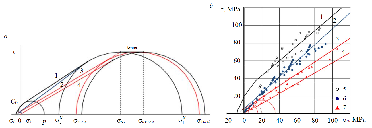
Fig.2. Construction of SS envelopes of rock and cracks (a); experimental data of comparative tests of marble (b) 1, 2 – the ultimate and residual strength of the rock; 3, 4 – the residual SS on cracks (JRC = 20; JRC = 0); 5, 6 – the ultimate and residual strength of the rock destroyed by triaxial compression; 7 – the residual cut strength with compression on cracks
It is generally assumed that in the Mohr diagram the limiting “critical” state corresponding to the maximum cross-section resistance tmax is characterized by the ratio of the minimum and maximum principal normal stresses equal to 1/3 [25, 33]. Taking this into account, the components of the limiting critical stress state (σ3crit and σ1crit) are taken as a characteristic of the SS along the most weakened surfaces. The critical state {σ = σav crit; τ = τmax} was considered as a transient stress limit state corresponding to the probabilistic nature of shear failure along plane cracks.
The assumptions made it possible to construct the envelope of the residual SS over flat cracks based on the results of testing a monolithic sample with indentors. In the Mohr diagram, the envelope of the residual shear strength along a plane crack is approximated by a complex of interrelated segments, the arc of the circle of the limiting circle of Mohr stresses {σ3crit = τmax; σ1crit = 3τ max}, for which the type of failure is probabilistic, and two rectilinear segments tangent to this circle and corresponding to stable types of macro-destruction (Fig.2, a, envelope 4). One of the segments passes through the origin at an angle of residual friction φr equal to 30° and touches the circle at the point with coordinates {σ = (2 – sinφr)τmax; τ = cosφrτmax}, while the horizontal segment touches the circle at the point with coordinates {σ = 2τmax; τ = τmax}.
In the Mohr diagram, the validity of such an approximation is confirmed by the coincidence of the lower boundary of the range of values of the residual SS for smooth cracks in marble, established during triaxial tests, with the calculated envelope of the residual SS for a flat, even crack (Fig.2, b).
In the range of average normal stresses corresponding to stable macro-fracturing of samples by cut, the envelope of the residual strength of the fractured rock is approximated by a segment of a single tangent to the Mohr circles corresponding to the maximum cut resistance and the conditional strength of the pure shear of the fractured rock [9, 37]. It is established that in the range of average normal stresses exceeding the conventional limits of strength under uniaxial compression, the envelopes of the residual SS of both the destroyed rock (Fig.2, a, envelope 2) and the residual SS along a rough crack with JRC = 20 (Fig.2, a, envelope 3) are reliably approximated by segments of the common tangents to the Mohr circles. They correspond to the conditional strength at pure shear of the destroyed rock (at the main normal stresses {–σt; σt}) and the maximum cut resistance τmax. In this case, the residual strength of the destroyed rock corresponds to the segment of the tangent to the Mohr circle common to the intact and destroyed rocks, and the residual SS along a rough crack corresponds to the segment of the tangent to the Mohr circle directed to the conditional point with coordinates {σ = σav; τ = τmax}.
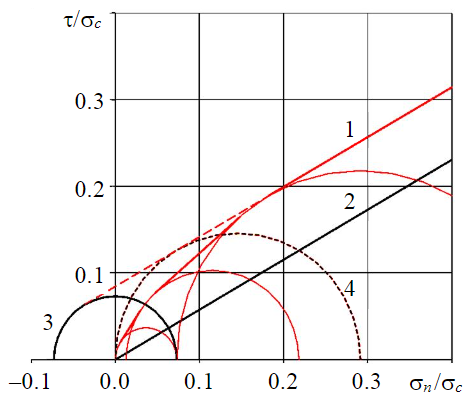
Fig.3. Construction of the calculated envelope of the relative residual SS over cracks in the range of low normal stresses for Kf = 7.5 1 – JRC = 20; 2 – JRC = 0; 3 – destroyed rock at pure shear; 4 – JRC = 20 (wall strength of cracks)
In the Mohr diagram, the validity of the proposed approximation for the envelope of shear strength for cracks with rough wall surfaces confirms that the upper limit of the range of values of the residual SS for rough cracks in marble, established during triaxial tests, coincides with the calculated envelope of residual shear strength (Fig.2, b, envelope 3).
At low normal stresses, the envelope of the residual strength of the destroyed rock has a non-linear form and touches the Mohr circle corresponding to the residual strength under uniaxial compression (Fig.3) [9]. To clarify the type of limit envelopes of the residual strength of the destroyed rock and the residual shear strength along cracks in this range of normal stresses, additional laboratory tests were carried out.
It has been experimentally established that at normal stresses that do not exceed the conditional limits of uniaxial compressive strength, the defining parameters of the certificate of the residual shear strength of the destroyed rock and cracks with a rough surface (JRC = 20) are: the absolute value of the tensile component of adhesion σt, the conditional limits of strength under uniaxial compression, which are similar to the parameters of the strength certificate of intact rock – C0 and uniaxial compressive strength σc:
where φr is the conditional friction angle along a rough crack with JRC = 20.
For the interval of normal stresses (less than σ0r), two limit stress states of crack surfaces are characteristic, described by arcs of Mohr circles and {σ3 = 0; σ1 = σt}, similar to the limit stress states of intact rock – the transition state from cut failure to separation failure {σ3 = –σt ; σ1 = p} and stress-separation failure . Rectilinear segments formed by common tangents to the circles (Fig.3, envelope 1) approximate the intervals between them.
Based on the results of the research, it is established that the deviation from the rectilinear form of the envelope of the residual shear strength for cracks with a rough surface (JRC = 20) occurs at an average normal stress that is less than the conditional uniaxial compressive strength σ0r. This stress state corresponds to a Mohr circle with a minimum principal normal stress equal to σt (Fig.4). The radius of this Mohr limit circle corresponds to the analog of the compressive component of the coupling p, which is numerically equal to the difference between the conditional uniaxial compressive strength and the coupling analog (σ0r – σt).
In the Mohr diagram, the envelope of the residual strength of the destroyed rock at low normal stresses can be approximated in the first approximation by a segment parallel to the same segment of the envelope of ultimate strength [9]. The shape of the curve in the low-stress region is refined in accordance with the integrated approach. It is experimentally established that the envelopes of the residual strength of rock destroyed during compression and cut along closed rough cracks (JRC = 20) practically do not differ in the normal stress range not exceeding σt. This interval corresponds to Mohr circles with values σ3 at most .
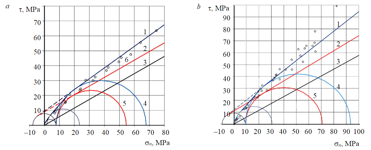
Fig.4. Design of calculated envelopes of residual SS in siltstone (a) and sandstone (b) 1 – destroyed rock; 2, 3 – crack (JRC = 20 and JRC = 0); 4, 5 – strength at s3 = st of the destroyed rock and crack walls (JRC = 20); 6 – residual strength of the rock destroyed by triaxial compression
Taking into account that the probabilistic state transitioning to stable cut failure of samples corresponds to the Mohr circle with the value σ3 equal to σt, the limit envelope in the interval characterized by the values σ3 from to σtcan be approximated by a common tangent to the corresponding Mohr circles corresponding to the cut along closed rough cracks. The parameters of Mohr circles that characterize similar stress states during shear over intact and fractured rock and closed rough cracks at low normal stresses are presented in Table 1.
Table 1
Correspondence of Mohr circle parameters for the characteristic stress limit states of intact and compression-fractured rocks and their cracks
|
Description of the ultimate stress state of intact rock |
Description of the shear surface |
|||||
|
Intact rock, MPa |
Rock destroyed by compression, MPa |
Stepped closed surface, MPa |
||||
|
σ3 |
σ1 |
σ3 |
σ1 |
σ3 |
σ1 |
|
|
Separation failure under compressive tension |
|
C0 |
0 |
σt |
0 |
σt |
|
Probabilistic separation failure or cutunder compressive tension |
–σt |
|
|
|
|
|
|
Cut failure under uneven compression |
C0 |
|
σt |
|
σt |
|
A single integrated approach to determining the ultimate and residual shear strength of rocks and the residual shear strength of closed rough cracks has been developed. In accordance with this, in the Mohr diagram, the limit envelope of the residual SS over rough cracks has a curved appearance at low normal stresses, rectilinear at an average level of normal stresses, and flattens out at a high level of stresses.
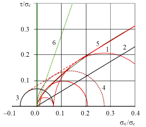
Fig.5. Construction of the calculated envelope of the relative residual SS on a rough (JRC = 20) crack in the range of low normal stresses for Kf = 8 See symbols 1-4 in Fig.3; 5 – by the Barton – Bandis criterion; 6 – the boundary of the scope of the Barton – Bandis criterion
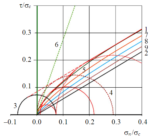
Fig.6. Construction of envelopes of relative residual SS for cracks of various morphological types in the range of low normal stresses for Kf = 7.5 1 – JRC = 20; 2 – JRC = 0; 3 – destroyed rock at pure shear; 4 – JRC = 20 (strength of crack wall); 5 – JRC = 20 (according to the Barton – Bandis criterion); 6 – the boundary of the scope of the Barton – Bandis criterion; 7 – JRC = 15; 8 – JRC = 10; 9 – JRC = 5
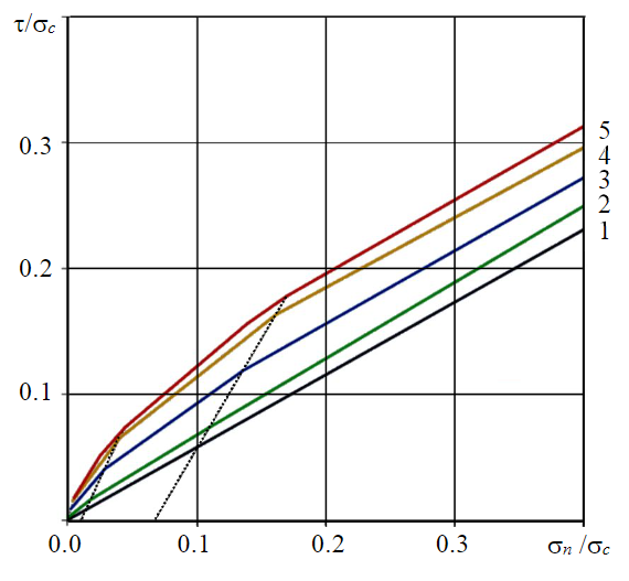
Fig.7. Construction of envelopes of relative residual SS for cracks of various morphological types in the range of low and medium normal stresses for Kf = 8 1 – smooth (JRC = 0); 2 – smooth type; 3 – wavy; 4 – stepped; 5 – rough (JRC = 20)
To substantiate the proposed integrated approach, comparative calculations of the shear strength of cracks are performed using the Barton – Bandis strength criterion formula (1) for the given values of the residual friction angle φr = 30° and the crack roughness coefficient JRC (0; 5; 10; 15; 20°). The calculated data are also compared with the experimental data of extreme tests for uniaxial and triaxial compression of monolithic samples containing natural and artificial cracks.
It is established, that at low normal stresses the deviation of the calculated values of shear strength for rough cracks calculated from the results of tests with spherical indentors from similar values calculated in accordance with the Barton – Bandis strength criterion for the value of the coefficient JRC = 20°, varies depending on the value of normal stress and brittleness of the rock and for Kf = 5-10 it is about 5 % (Fig.5). The deviation of the calculated values of shear strength for rough cracks in the range of average normal stresses exceeding the conventional limits of strength under uniaxial compression increases from 3-6 % in the range σ ≈ 0.2-0.6σc to 6-9 % at σ = 0.7σc and reaches 10-18 % at σ = σc.
A comparison of the calculated shear strength indicators performed in relative (in fractions of σc) values of normal stress showed, that at low normal stresses for most sedimentary rocks (mudstones, marls, siltstones, limestones, clay, and carbonate sandstones), which correspond to the values of the rock brittleness coefficient Kf from 6.5 to 8.5, the intervals of the possible values of shear strength (from the minimum values corresponding to flat cracks to the maximum values corresponding to stepped rough cracks) are almost identical. For more brittle rocks (Kf ≥ 10), the range of possible strength values when evaluating strength using the proposed integrated approach is narrower, and for more ductile rocks (5 ≤ Kf ≤ 6) it is wider.
It is established that in the normal stress range 0.01-0.7σc, the shear strength envelopes for flat, even and stepped rough cracks constructed in accordance with the proposed integrated approach are in close agreement with the family of limit envelopes of residual SS for the values of the JRC coefficient from 0 to 20° constructed in accordance with the Barton – Bandis criterion (Fig.6). Considering this, when constructing limit envelopes to take into account the roughness effect in the low-and medium-normal stress ranges, it is recommended to follow the proportional dependence of the SS change on the roughness coefficient, similar to formula (1).
An express method for assessing the residual shear strength of rocks based on rough closed cracks is developed, in which an improved method of loading the sample with spherical indentors is used as the basic test method. The express method implements the transition from data of mechanical tests of intact samples with spherical indentors to indicators of joint strength for cracks in the rock mass based on a unified approach to assessing the shear strength of rocks for closed cracks, taking into account the level of normal stresses and crack roughness measured in natural conditions. At the same time, both the roughness scale developed by Barton [16], and the roughness estimation in the first approximation based on the morphological type of cracks can be used to describe the crack roughness [34].
The express method includes the following steps:
Estimating the crack wall roughness and normal stresses in the field.
- Conducting tests for splitting intact small-sized rock samples by loading with spherical indentors in laboratory or field conditions; building a strength certificate and determining the SS parameters of the intact rock based on the results of testing samples with spherical indentors in accordance with the methodology (see Fig.1, b).
- Plotting residual strength envelopes on the Mohr diagram and determining the parameters of the residual SS from stepped rough (JRC = 20) and flat smooth cracks (JRC = 0). When constructing the envelope of the residual SS over a stepped rough crack, the limit stress states are taken as initial data. They are described by arcs of Mohr circles {σ3 = 0; σ1 = σt}, , { σ3 = σt ; σ1= (2σ0r– σt)} and the conditional point where the intact rock reaches the maximum cut resistance τmax at high normal stresses with coordinates {σ = σav; τ = τmax} (see Fig.2, envelope 3). In this case, rectilinear segments formed by common tangents to the circles (see Fig.3) approximate the intervals between arcs.
- Plotting the envelope of the residual SS along the crack on the Mohr diagram, taking into account the roughness and level of normal stresses under natural conditions, and determining the parameters of the residual SS along the crack. For this purpose, on the Mohr diagram, segments are drawn that connect points on the envelopes of the residual SS for stepped rough and flat smooth cracks and correspond to the same characteristic values σ3 equal to 0, , σt, and the conditional point with coordinates {σ = σav; τ = τmax} (see Fig.2, a, envelope 3). The segments are divided into intervals by points that correspond to the specified values of JRC relative to JRC = 20 (Fig.7). Then, envelopes of the residual shear strength corresponding to the specified roughness of the crack walls are drawn through the family of these points. The calculated parameters of the residual strength envelope (conditional residual coupling Cr and the residual friction angle φr) are calculated for the specified intervals of normal stresses.
As an example of using the express method Fig.7 shows the construction of envelopes of the relative residual SS along closed cracks of smooth, wavy, and stepped morphological rock types according to the domestic classification [34]. They correspond to the estimated values of the roughness coefficient calculated by formula (1): for smooth plane cracks, JRC = 0-5; smooth wavy tectonic cracks, JRC = 8-12; and rough wavy cracks, JRC = 15-20 [34]. As initial data on crack roughness, the average values for the types are taken. The set value K f = 8 is typical for sedimentary rocks such as siltstones and limestones [8].
The results of calculating the average values of the envelope parameters of the relative residual shear strength (relative Cr/σc and φr) for closed cracks of various morphological types for given normal stress intervals corresponding to low, medium and high levels of normal stresses are presented in Table 2.
The proposed express method for determining the residual shear strength from closed cracks can also be implemented based on the data for determining two other strength characteristics of intact rock – the strength limits under uniaxial compression σc and tension σT. In this case, the values of the stretching σt and compressive p components of the coupling С0 required for calculations are pre-calculated algebraically by the given formulas (4)-(6).
Table 2
Calculated values of the parameters Cr/σc and φr of the envelopes of the residual SS of rock along closed cracks of various morphological types (Kf = 8)
|
Morphological type of cracks |
Interval 1 |
Interval 2 |
Interval 3 |
||||||
|
σ/σc, MPa |
Cr/σc |
jr, deg |
σ/σc, MPa |
Cr/σc |
jr, deg |
σ/σc, MPa |
Cr/σc |
jr, deg |
|
|
Smooth |
0.0006-0.017 |
0.002 |
39 |
0.017-0.110 |
0.004 |
32 |
0.110-2.773 |
0.007 |
31 |
|
Wavy |
0.0025-0.029 |
0.006 |
50 |
0.029-0.136 |
0.019 |
36 |
0.136-2.838 |
0.040 |
30 |
|
Stepped |
0.0044-0.041 |
0.007 |
54 |
0.041-0.162 |
0.040 |
39 |
0.162-2.904 |
0.074 |
30 |
Conclusion
New experimental data are presented on the relationship between the residual shear strength of rocks along closed cracks and the functional characteristics of intact rocks – the tensile σt and compressive p components of the ultimate shear resistance without normal stresses (adhesion) C0, the roughness of the crack surfaces, and the level of normal stresses.
It is established that in the Mohr diagram, the limit envelope of the residual SS over rough cracks has a curved appearance at “low” normal stresses, rectilinear at an average level of normal stresses, and flattens out at a high level. At the same time in the range of low normal stresses the determining parameters of the certificates of the residual shear strength of rock and cracks with a stepped rough surface are the absolute value of the tensile component σt of coupling C0 and the conditional limits of strength under uniaxial compression σ0R and σ0r, which are similar to the parameters C0 of the uniaxial compression σc. In the range of average normal stresses, the envelopes of residual strength are approximated by straight-line segments of common tangents to the circles of Mohr circles corresponding to the limit states of the destroyed rock during pure shear and quasi-plastic deformation.
A single integrated approach to determining the shear strength of intact and fractured rocks and the residual shear strength of closed rough cracks is developed based on an assessment of the ultimate stresses at which the type of fracture is probabilistic. The approach provides for the allocation of stress intervals corresponding to different types of fracture, for each of which a strength criterion expressed in terms of the functional characteristics of intact rock σt and p,is proposed.
The results of comparative mechanical tests of rocks and comparative calculations of crack strength, according to the integrated approach and in accordance with the Barton – Bandis strength criterion, indicate the validity of the proposed approach. It is established that in the normal stress range 0.01-0.7σc, the shear strength envelopes for smooth flat and stepped rough cracks constructed in accordance with the developed integrated approach are in close agreement with the family of limit envelopes of the residual SS for values of the JRC coefficient from 0 to 20°, constructed in accordance with the Barton – Bandis criterion.
An express method for estimating the residual shear strength of rocks from cracks with a rough surface has been developed, in which an improved method of loading samples with spherical indentors is used as the basic test method. The express method implements the transition from the data of mechanical tests of samples with spherical indentors to the SS indicators for cracks in the rock mass, taking into account the level of normal stresses and the roughness of the crack surfaces measured in full-scale conditions. In this case the roughness scale developed by Barton is used. The express method is informative and accessible in the field using technically simple loading devices. Testing of small-sized samples of irregular shape is allowed.
References
- Trushko V.L., Protosenya A.G. Prospects of Geomechanics Development in the Context of New Technological Paradigm. Journal of Mining Institute. 2019. Vol. 236, p. 162-166. DOI: 10.31897/PMI.2019.2.162
- Trushko V.L., Sergeev I.B., Shabarov A.N. The Development of Geomechanical Engineering in Mining. ISRM European Rock Mechanics Symposium – EUROCK 2018, 22-26 May 2018, Saint Petersburg, Russia. 2018. OnePetro, 2018. Vol. 1, p. 95-104. N ISRM-EUROCK-2018-009.
- Zuev B.Yu. Methodology of modeling nonlinear geomechanical processes in blocky and layered rock masses on models made of equivalent materials. Journal of Mining Institute. 2021. Vol. 250, p. 542-552. DOI: 10.31897/PMI.2021.4.7
- Shabarov A.N., Zuev B.Y., Krotov N.V. Prospects of the physical model-based study of geomechanical processes. ISRM European Rock Mechanics Symposium – EUROCK 2018, 22-26 May 2018, Saint Petersburg, Russia. 2018. OnePetro, 2018. Vol. 1, p. 423-430. N ISRM-EUROCK-2018-052.
- Protodyakonov M.M., Voblikov V.S., Il'nitskaya E.I. The method of determining the strength of rocks on samples of irregular shape. Moscow: Izd-vo Instituta gornogo dela im. A.A.Skochinskogo, 1961, p. 8 (in Russian).
- Kartashov Yu.M., Matveev B.V., Mikheev G.V., Fadeev A.B. Strength and deformability of rocks. Moscow: Nedra, 1979, p. 269 (in Russian).
- Franklin J.A. Suggested Methods for Determining Points Load Strength. International Journal of Rock Mechanics and Mining Sciences & Geomechanics Abstracts. 1985. Vol. 22. Iss. 2, p. 51-60. DOI: 10.1016/0148-9062(85)92327-7
- Korshunov V.A., Kartashov Y.M. A new technique for the determination of ultimate strength in extention of rocks. Journal of Mining Institute. 2011. Vol. 190, p. 202-206 (in Russian).
- Korshunov V.A., Solomoichenko D.A., Bazhukov A.A. Strength Estimation of Fractured Rock Using Compression – A Specimen with Spherical Indenters. ISRM European Rock Mechanics Symposium – EUROCK 2018, 22-26 May 2018, Saint Petersburg, Russia. 2018. OnePetro, 2018. Vol. 1, p. 299-305. N ISRM-EUROCK-2018-034.
- Fisenko G.L. Strength characteristics of the rock mass. Rock mechanics and surveying. Moscow: Ugletekhizdat, 1959, p. 91-100 (in Russian).
- Ismail M.K.A., Mohd-Nordin M.M., Hasan A.S.Md. et al. Shear strength behaviour of rock joint material influenced by different weathering grade. Journal of Physics: Conference Series. 2019. Vol. 1349. Iss. 1. N 012069. DOI: 10.1088/1742-6596/1349/1/012069
- Li Y., Oh J., Mitra R., Canbulat I. A Fractal Model for the Shear Behaviour of Large-Scale Opened Rock Joints. Rock Mechanics and Rock Engineering. 2017. Vol. 50. Iss. 1, p. 67-79. DOI: 10.1007/s00603-016-1088-8
- Fisenko G.L. Methods of quantitative assessment of structural weakening of the rock mass in connection with the analysis of its stability. Sovremennye problemy mekhaniki gornykh porod. Leningrad: Nauka, 1972, p. 21-29 (in Russian).
- Stigsson M., Mas Ivars D. A Novel Conceptual Approach to Objectively Determine JRC Using Fractal Dimension and Asperity Distribution of Mapped Fracture Traces. Rock Mechanics and Rock Engineering. 2019. Vol. 52, p. 1041-1054. DOI: 10.1007/s00603-018-1651-6
- Ríos-Bayona F., Johansson F., Mas-Ivars D. Prediction of Peak Shear Strength of Natural, Unfilled Rock Joints Accounting for Matedness Based on Measured Aperture. Rock Mechanics and Rock Engineering. 2021. Vol. 54. Iss. 3, p. 1533-1550. DOI: 10.1007/s00603-020-02340-8
- Barton N. Shear strength criteria for rock, rock joints, rockfill and rock masses: Problems and some solutions. Journal of Rock Mechanics and Geotechnical Engineering. 2013. Vol. 5. Iss. 4, p. 249-261. DOI: 10.1016/j.jrmge.2013.05.008
- Patton F.D. Multiple Modes of Shear Failure in Rock. 1st ISRM Congress, 25 September – 1 October 1966, Lisbon, Portugal. OnePetro, 1966. Vol. 1, p. 509-513. N ISRM-1CONGRESS-1966-087.
- Gudman R. Rock mechanics. Moscow: Stroiizdat, 1987, p. 232 (in Russian).
- Latyshev O.G., Frants V.V., Prishchepa D.V. Modeling and the Forecast of Rock Strength at the Shift of Rocks along the Fissure. Minerals and Mining Engineering. 2017. N 2, p. 50-56 (in Russian).
- Protosenya A.G., Verbilo P.E. Research of compression strength of fissured rock mass. Journal of Mining Institute. 2017. Vol. 223, p. 51-57. DOI: 10.18454/PMI.2017.1.51
- Protosenya A.G., Iovlev G.А. Prediction of spatial stress-strain behavior of physically nonlinear soil mass in tunnel face area. Mining Informational and Analytical Bulletin. 2020. N 5, p. 128-139 (in Russian). DOI: 10.25018/0236-1493-2020-5-0-128-139
- Protosenya A., Vilner M. Assessment of Excavation Intersections’ Stability in Jointed Rock Masses Using the Discontinuum Approach. Rudarsko-geološko-naftni zbornik. 2022. Vol. 37. Iss. 2, p. 137-147. DOI: 10.17794/rgn.2022.2.12
- Myuller L. Engineering geology. Mechanics of rock masses. Moscow: Mir, 1971, p. 240 (in Russian).
- Kuznetsov G.N. Mechanical properties of rocks. Tasks and methods of its study in connection with the issues of rock pressure control. Moscow: Ugletekhizdat, 1947, p. 180 (in Russian).
- Tarasov B.G. Regularities of deformation and destruction of rocks at high pressures: Avtoref. dis. ... d-ra tekhn. nauk. St. Petersburg: LGI, 1991, p. 46 (in Russian).
- Ladanyi B., Archambault G. Simulation of the Shear Behavior of a Jointed Rock Mass. The 11th U.S. Symposium on Rock Mechanics (USRMS), 16-19 June 1970, Berkeley, California. OnePetro, 1970, p. 105-125. N ARMA-69-0105.
- Bieniawski Z.T. Estimating the strength of rock materials. Journal of the South African Institute of Mining and Metallurgy. 1974. Vol. 74. N 8, p. 312-320.
- Eberhardt E. The Hoek-Brown Failure Criterion. Rock Mechanics and Rock Engineering. 2012. Vol. 45, p. 981-988. DOI: 10.1007/s00603-012-0276-4
- Protodyakonov M.M. Generalized equation of envelopes to limiting circles of Mohr stresses. Investigation of physical and mechanical properties of rocks in relation to the problems of rock pressure control. Moscow: Izd-vo Akademii nauk SSSR, 1962, p. 82-89 (in Russian).
- Labus J.F., Zang A. Mohr-Coulomb Failure Criterion. Rock Mechanics and Rock Engineering. 2012. Vol. 45, p. 975-979. DOI: 10.1007/s00603-012-0281-7
- Singh H.K., Basu A. Evaluation of existing criteria in estimating shear strength of natural rock discontinuities. Engineering Geology. 2018. Vol. 232, p. 171-181. DOI: 10.1016/j.enggeo.2017.11.023
- Thirukumaran S., Indraratna B. A review of shear strength models for rock joints subjected to constant normal stiffness. Journal of Rock Mechanics and Geotechnical Engineering. 2016. Vol. 8. Iss. 3, p. 405-414. DOI: 10.1016/j.jrmge.2015.10.006
- Quansheng Liu, Yongchao Tian, Dongfeng Liu, Yalong Jiang. Updates to JRC-JCS model for estimating the peak shear strength of rock joints based on quantified surface description. Engineering Geology. 2017. Vol. 228, p. 282-300. DOI: 10.1016/j.enggeo.2017.08.020
- Mogilevskaya S.E. The express method of VNIIG for determining the parameters of shear resistance by cracks in rocks. Experience and prospects of use. Geotechnics. Assessment of the condition of foundations and structures: Trudy mezhdunarodnoi konferentsii, 13-16 iyunya 2001, St. Petersburg, Russia. 2001. Vol. 1, p. 41-49 (in Russian).
- Liren Ban, Weisheng Du, Tianwei Jin et al. A roughness parameter considering joint material properties and peak shear strength model for rock joints. International Journal of Mining Science and Technology. 2021. Vol. 31. Iss. 3, p. 413-420. DOI: 10.1016/j.ijmst.2021.03.007
- Barton N.R. Shear Strength of Rock, Rock Joints and Rock Masses. The 11th U.S. Symposium on Rock Mechanics (USRMS), 16-19 June 1969, Berkeley, California. OnePetro, 1969, p. 3-16. N ARMA-69-0105.
- Read J., Stacey P. Guidelines for Open Pit Slope Design. Clayton: CSIRO Publishing, 2009, p. 496. DOI: 10.1071/9780643101104
- Jie Yang, Guan Rong, Di Hou et al. Experimental study on peak shear strength criterion for rock joints. Rock Mechanics and Rock Engineering. 2016. Vol. 49, p. 821-835. DOI: 10.1007/s00603-015-0791-1
- Zhi Cheng Tang, Louis Ngai Yuen Wong. New Criterion for Evaluating the Peak Shear Strength of Rock Joints Under Different Contact States. Rock Mechanics and Rock Engineering. 2016. Vol. 49. Iss. 4, p. 1191-1199. DOI: 10.1007/s00603-015-0811-1
- Rihong Cao, Hang Lin, Ping Cao. Strength and failure characteristics of brittle jointed rock-like specimens under uniaxial compression: Digital speckle technology and a particle mechanics approach. International Journal of Mining Science and Technology. 2018. Vol. 28. Iss. 4, p. 669-677. DOI: 10.1016/j.ijmst.2018.02.002
- Korshunov V.A., Kartashov Y.M., Kozlov V.A. Determination of indices of strength certificate оf rocks using the method of specimens failure with spherical indentors. Journal of Mining Institute. 2010. Vol. 185, p. 41-45 (in Russian).
- Korshunov V.A., Tsirel S.V., Melnikov N.Ya., Bazhukov A.A. Geomechanical Substantiation of Calculate Indentors of the Rock Mass Strength for Slopes Stability Analysis of Open Pit. ISRM European Rock Mechanics Symposium – EUROCK 2018, 22-26 May 2018, Saint Petersburg, Russia. OnePetro, 2018. Vol. 2, p. 1053-1058. N ISRM-EUROCK-2018-149
- Pavlovich A.A., Korshunov V.A., Bazhukov A.A., Melnikov N.Y. Estimation of Rock Mass Strength in Open-Pit Mining. Journal of Mining Institute. 2019. Vol. 239, p. 502-509. DOI: 10.31897/PMI.2019.5.502