Substantiation and selection of the design parameters of the hydroficated equipment complex for obtaining backfill mixtures from current enrichment tailings
- 1 — Ph.D., Dr.Sci. Saint Petersburg Mining University ▪ Orcid
- 2 — Ph.D. Design Engineer OOO “Signal” ▪ Orcid ▪ Elibrary ▪ Scopus
- 3 — Ph.D. Associate Professor Saint Petersburg Mining University ▪ Orcid

Abstract
The issue of the influence of the concentration of the solid phase on the reduction of energy costs and specific energy consumption during pulp transportation is considered. The procedure for preparing slurry from the current enrichment tailings is shown. A scheme is given and the operation of a hydroficated unit for thickening and hydraulic transport of backfill mixtures is described. A diagram of the movement of solid particles in one of the units of the complex – a lamellar thickener is shown. The summary table shows the main design parameters and characteristics of the lamellar thickener. A general view of the laboratory setup used for experimental studies with slurry at various concentrations is given. An example of calculating productivity, density and specific load is presented. The dependence of the shear stress on the velocity gradient was determined for various pulp concentrations. Experimental studies of the process of thickening the production of slurry from the current enrichment tailings have been carried out. It was found that the geometric dimensions of the thickener depend on the concentration of the solid phase in the transported mixture. It is concluded that the flow rate of the slurry and the head loss are functions of the rheological characteristics of the viscoplastic slurry and can be calculated from the derived calculated dependencies.
None
Introduction
The main tasks of mining and technologies related to the hydraulic transport of mineral processing products are further reduction of energy costs, reduction of specific energy intensity of technological processes and development of waste-free process technologies [1-3]. The defining and effective direction of solving the problems of non-waste technologies is the use of underground mining systems with backfilling of mined-out space [4-6]. This process should include the use of production wastes (tailings) [7-9]. This will affect the more intensive development of deposits, will allow solving the issues of subsoil and environmental protection [10, 11].
Currently, ore mining by systems with backfilling of mine workings in Russia is no more than 24 % of the total mining by underground mining. Most non-ferrous metallurgy mining enterprises have processing plants. Increasing volumes of stowing operations determine the need to create and use new stowing mixtures that provide high physical and mechanical properties of the stowing mass with a minimum consumption of binder material (cement) [12-14]. With an increase in the fineness of the grinding of the solid phase due to the depletion of the ore, the yield of fine grades of fineness – the current enrichment tailings – increases significantly [15-17]. It is the current tailings that can be the main material for filling mixtures [18-20].
Preparation of the mixture based on the current enrichment tailings involves several technological operations [21-23]: thickening of the tailing pulp in thickening devices to a high concentration of the solid phase; hydraulic transportation of the condensed mixture with the help of pumping equipment to the backfilling complexes of the mine into supply tanks [24-26]; dosing of condensed slurry in special activator devices and mixing the mixture with a binder material; delivery and placement of the prepared backfill mixture into the mine working [27-29].
The initial and main technological operation of preparing the filling mixture is the thickening of the slurry coming after the technological process of ore beneficiation [30-32]. In the practice of mining, various thickeners are used, differing in design and mode of action: radial, hydrocyclones, centrifuges, etc. [33, 34]. In recent years, plate thickeners have been used [35-37]. A distinctive feature of plate-type thickeners from traditional radial thickeners is their smaller overall dimensions with equal specific load per unit area of sedimentation.
Despite the significant and practically confirmed advantages of lamellar thickeners, equipment of this type have not yet found wide application in hydrotransport technologies in tailings pulp thickening schemes to obtain high-concentration slurries. The problem lies in the insufficient theoretical and experimental substantiation of the process of sedimentation of solid particles in interplate channels and the mechanism of formation of the structure of a thickened sediment. This does not allow creating an effective design of a lamellar thickener for obtaining highly concentrated slurries for preparing filling mixtures [38-40].
The purpose of the work is to identify the parameters under which the equipment will operate with lower energy and operating costs. The paper considers in aggregate the processes of thickening (dehydration) of fine tailings, hydraulic transportation of highly concentrated slurry as an inert filling mixture filler, and the dependence of the energy characteristics of soil pumps on the rheological properties of pumped backfill mixtures.
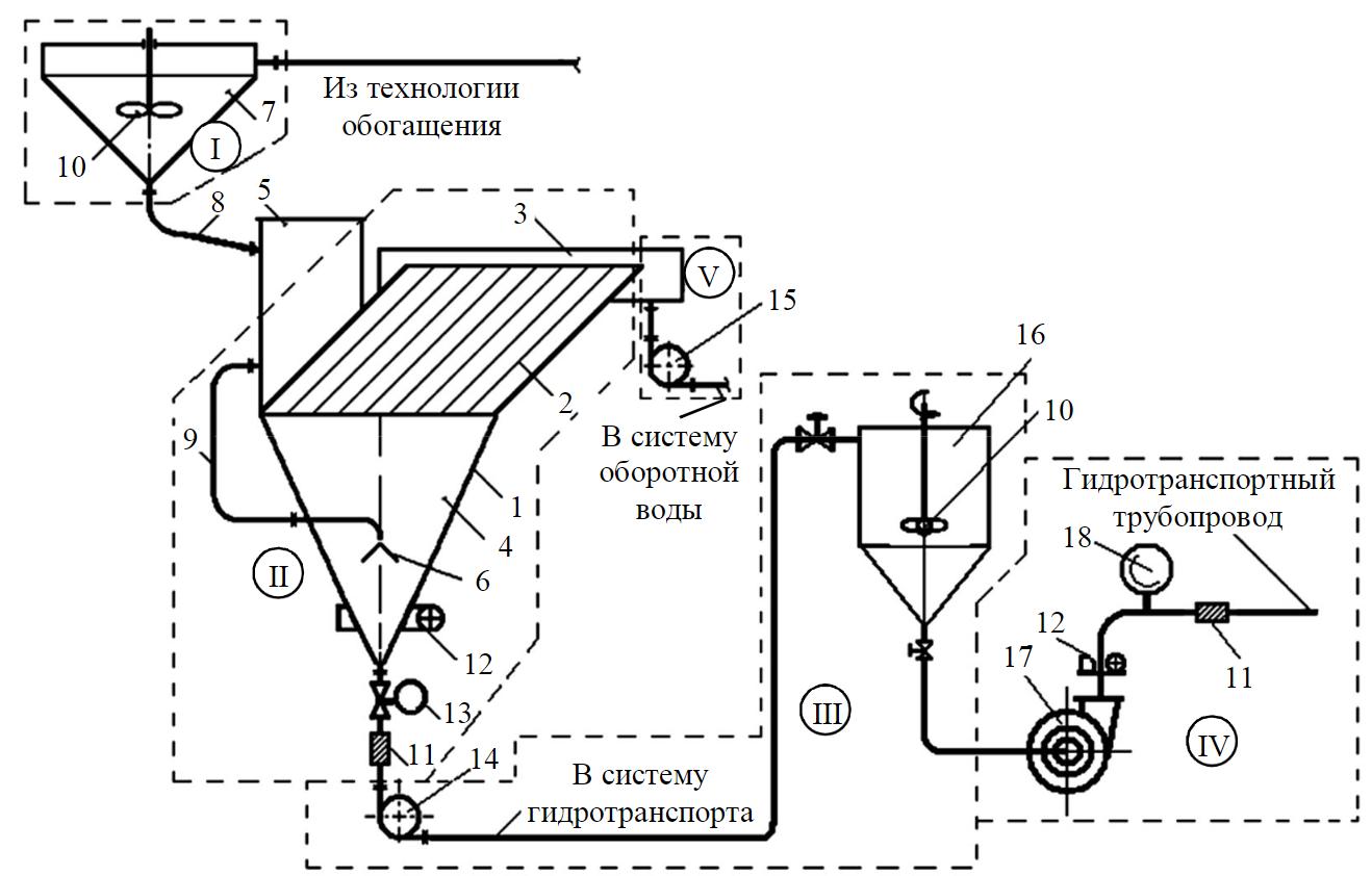
Fig.1. A hydroficated unit for thickening and hydraulic transport of filling mixtures
Methods
Hydroficated unit (Fig.1) for preparation and transportation of backfill mixtures consists of sequentially mounted blocks: I – consumption (reception) of the incoming slurry; II – dehydration; III – supply of the condensed mixture to the pump; IV – hydrotransport; V – drain removal.
The thickened slurry (current tailings of ore dressing) comes from the dressing technology to the hopper of the initial pulp 7 with an impeller 10 (to prevent the settling of solid particles). Further, the slurry through the supply pipeline 8 fills the surge tank 5 and the volume of the thickener is loaded through the pipeline 9 (bunker storage 4, block of inclined plates 2 and drain tray 3). The slurry flows between the plates of the thickener 1 with a baffle cap 6, where precipitation (sedimentation) of solid particles occurs along the entire length of the channel. The sediment of solid particles formed on the lower plates, under the action of its own weight, moves from top to bottom and is deposited in the lower part of the storage hopper 4, where a thickened slurry is formed. Recycled water overflows through the upper edges of the plates into the drain tray 3, installed around the entire perimeter of the block of plates, and is removed using a pump 15 to the tailings.
The slurry condensed to the required concentration with the help of a slurry pump 14 is fed through a pipeline with a valve 13 into the condensed slurry bin 16, then it enters the hydrotransport pipeline with the help of a soil pump 17 and is transported to the stowing complex, where the hardening stowing mixture is prepared. The volume of the mixture and the pressure of this system is measured by flow meters 11 and 12 and pressure gauge 18.
A distinctive feature of the hydroficated complex under consideration is that all technological operations for preparing the filling mixture and hydraulic transportation are combined in one unit. In this configuration, the processes of regulation and control of the technological process of thickening and hydraulic transport of the thickened filling mixture are simplified. Studies of the hydroficated complex according to the scheme shown in Fig.1 were carried out in the laboratory of the Mining University on a prototype plate thickener. Tailings of copper ore enrichment of the Dzhezkazgan Mining and Metallurgical Plant were used as experimental slurries.
The main elements of the thickening and hydraulic conveying unit are the plate thickener and the soil pump. A feature of the working process of lamellar (thin-layer) thickeners is that due to the special design of the thickening unit 2, solid particles of tailings of small classes, up to 0.038 mm, are captured and sent to the thickened product. The principle of operation of plate thickeners is countercurrent. The thickened flow containing particles of a given granulometric composition moves from bottom to top, and the dehydrated sediment of solid particles moves along the lower plates in the opposite direction – from top to bottom and accumulates in storage bin 4. The operating mode of the hydrotransport unit is controlled by a set of instruments: density meters VIP-2MR; induction flowmeters EMIS-MAG 270 at the outlet of the storage hopper and at the discharge pipe of the pump.
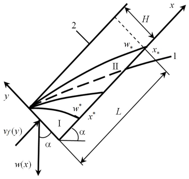
Fig.1. A hydroficated unit for thickening and hydraulic transport of filling mixtures
The main design parameter of lamellar thickeners is the length of the solid particles settling zone – the plates and the channel formed by the lower and upper plates. Figure 2 shows the scheme of solid particles settling in the space between the lower (1) and upper (2) plates. In Fig.2: L is the total length of the plates; Н is the distance between the lower and upper plates; a is plate inclination angle, deg; w*, w* is maximum and minimum sedimentation velocity of solid particles, m/s; x*, x* is distance of solid material deposit formation on the lower plates; νf(y) is the velocity of the slurry inlet flow averaged over the cross-sectional area of the channel, m/s; I и II are areas of complete turbidity (all particles of the granulometric composition of the slurry are present) and gradual clarification of the inlet stream of the slurry.
A stationary flow of slurry in the channel between the plates is provided with a limited value of the Reynolds and Froude numbers. For a stationary flow regime, the assumption about the gravitational drift of solid particles of particle size distribution from the streamlines of the slurry is valid. Preliminary experiments have shown that Recr number for providing a laminar and stationary regime does not exceed 400, i.e.
where Hr – channel height, m; νc – average slurry speed, m/s; ν – kinematic viscosity of slurry, m2/s.
For the stationary regime of the slurry flow, the values of the main design and geometric parameters of the plate thickener (Table 1) were obtained, the totality of which constitutes a mathematical model of the working process of the plate thickener.
Table 1
Structural, geometric parameters and characteristics of the plate thickener
|
Parameter |
Obtained values |
|
Average slurry velocity, m/s |
|
|
Channel height, m |
|
|
Section of plates with laminar flow, m |
|
|
Total length of plates, m |
|
|
Angle of inclination of plates, deg |
|
|
Channel area, m2 |
|
|
Drain area, m2 |
|
| Height of the inclined part, m |
|
|
Capacity of the lower part, m3 |
|
|
Productivity for solid material, t/h |
|
|
Structural and geometric parameters of the thickener: 1 – discharge channel; 2 – storage hopper; 3 – loading pipeline; 4 – block of plates; 5 – surge tank; 6 – sedimentation channel; 7 – drain tray; 8 – drain channel; 9 – inclined plates |
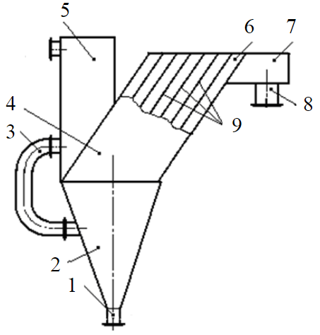 |
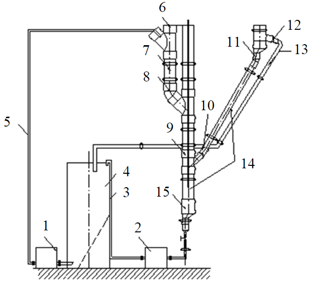
Fig.1. A hydroficated unit for thickening and hydraulic transport of filling mixtures
From the above calculations, it can be seen that the geometric and design characteristics of the working process of the plate thickener are determined by the slurry flow regime in the interplate channels Re, the hydraulic size of the solid particles of particle size distribution P(di), and the capacity at the inlet to the thickener Qi.
Results
Experiments were carried out to check the adequacy of the obtained mathematical model. Studies of thickening processes were carried out on a specially designed laboratory sample of a thin-layer lamellar thickener (Fig.3).
The studied slurry with a given concentration and particle size distribution of solid particles was loaded into a supply tank and pumped through the experimental circuit. Upon reaching the steady state operation of the bench (after 5-10 min), samples were taken at the thickener outlet (from pipe 13) and in its unloading (3). The samples were analyzed for density, the concentration of solid particles was determined. During the experiments, the height of the thickened layer was measured in the lower part of the thickener through a transparent insert. According to the nature of the change in the height of the thickened layer, the stability of the thickener operation mode was determined. Overflow and discharge solids data were used to determine the effective thickening area from feed, thickened and overflow products. Based on the results of work at several concentrations of the solid phase, taking into account the specific parameters of the thickener, the most efficient mode was chosen in terms of the maximum concentration in the condensed product and the lower solid content in the pulp overflow. The experimental results in terms of specific parameters were recalculated for the operation of industrial models of gravity thickeners.
When performing experimental studies on a laboratory lamellar thickener, measurements of the initial flow of the pulp prepared from the tailings of copper ore enrichment were made. The content of the solid phase at the inlet to the thickener was about 5 % by volume of the mixture cisc. The performance of the loading pump (2 in Fig.3) was about 5 l/min. The capacity of the system for solid material was about 0.25·10–3 m3/min (0.675 kg/min). During the experiments, the time of settling of the solid phase in the lower part of the thickener was measured up to a given height of the storage hopper, which was used to determine the rate of constrained settling of solid particles. The height of the layer of settled particles was observed through a glass insert. Changing the flow rate of the thickened slurry at the outlet of the thickener using a plug valve on the outlet pipe changed the concentration of solids in the thickened slurry. The consumption of clarified water and the content of solid particles in it were measured. To measure the distribution of the concentration of solid particles along the height of the thickener (along the height of the vertical part), holes 10 mm in diameter were drilled in the casing, through which pulp samples were taken into special calibrated containers [30]. After sampling, the holes were plugged with plastic plugs. The flow rate was determined by the filling time of the measuring container. The concentration of solid particles in the samples was determined by weighing on a balance beam with weights. Main measured quantities: sampling time t, s; measurement of the volume of the selected sample Wpr, m3; sample weighing Gpr, g; height of the compacted sediment layer h, mm; cross-sectional area of pulp passage Sef, mm2; amount of solid phase in the slurry qsol, t; concentration of the solid phase сsol, %.
The values of these parameters were used to calculate:
- performance of the thickener in the unloading of the apparatus
- thickened slurry density
- specific load per effective thickening area
where D – diameter of laboratory thickener, D = 50 mm; ρsol – density of copper ore tailings, ρsol = 2700 kg/m3.
Experimental data on the thickening of the slurry of copper ore tailings in a laboratory lamellar thickener are given in Table 2.
Table 2
Experimental data on the study of slurry thickening of copper ore tailings
|
Time, s |
Volume samples, ml |
Weight samples, g |
Mixture density, kg/m3 |
Concentration, % |
Specific load for pulp, m3/(h∙m2) |
Specific load for solid material, t/(h∙m2) |
Sediment height, m |
|
15 |
312.5 |
413.43 |
1323 |
20.0 |
38.21 |
18.34 |
0.318 |
|
20 |
277 |
413.40 |
1492 |
29.0 |
25.40 |
20.57 |
0.212 |
|
25 |
260 |
429.50 |
1652 |
38.4 |
19.10 |
20.68 |
0.159 |
|
30 |
250 |
453.06 |
1812 |
47.8 |
16.30 |
22.00 |
0.127 |
The results of experiments and experimental data indicate the dependence of the geometric parameters of the thickener on the value of the concentration in the unloading apparatus. When the concentration changed, the height of the sediment layer in the discharge part of the thickener and the specific load on the effective thickening area changed. With a change in concentration in the unloading of the thickener from 0.2 to 0.5 %, the height of the compacted layer varied from 318 to 127 mm. In this case, the specific load varied from 38.21 m3/(h∙m2) for slurry and 18.34 t/(h∙m2) for solid material up to 16.29 m3/(h∙m2) and 22 t/(h∙m2). Moreover, the specific load on the pulp decreased with an increase in the concentration of the condensed slurry, and the load on the solid phase of the flow increased.
During the experiments, samples were taken from the inclined module in three of its sections: at the inlet, in the middle, and at the outlet (thickener drain). The granulometric composition of solid particles in the selected samples was determined by sieve analysis. To do this, the samples were filtered, dried and dispersed through a set of sieves. The determination of the amount of material by size classes was carried out by weighing individual classes. The accuracy of sieve analysis was about 5 %. Based on the sieve analysis, the weighted average diameter of solid particles was calculated.
As a preliminary conclusion based on the results of experiments on a laboratory thickener with a thin-layer module, we note that the main part of fine particles is deposited in an inclined channel, and the geometric dimensions of the thickener determine the concentration of the solid phase in the thickened product. With a change in the flow rate in the unloading of the thickener and a constant flow rate at its inlet, the height of the compacted sediment and the concentration of solids in the thickened slurry change. The capacity of the thickener for solid material and the flow rate at the inlet remained constant in all experiments.
Hydraulic transport of condensed slurry to the stowing complex
An analysis of the experimental results shows that a highly concentrated viscoplastic slurry, the flow of which is described by the Shvedov – Bingham formula [41], forms the slurry in the thickener discharge:
where τ – shear stress; τ0 – static stress; μ – dynamic viscosity coefficient; $\frac {dV}{dn}= \dot γ$ – velocity gradient (shear rate).
This preliminary conclusion about the nature of the thickened slurry is confirmed by experimental data obtained using a rotational viscometer. In the Shvedov – Bingham formula, the defining parameter is viscosity, which varies depending on the concentration of solid particles from the minimum (viscosity of recycled water) to the maximum values characteristic of pasty slurries. The experiments were carried out on an automatic universal rotational viscometer Rheotest RN 4.1. During the experiments, the dependence of the shear stress on the shear rate gradient for various concentrations of solid particles сν in the volume of the studied slurry was determined (Table 3).
Table 3
The values of the measured parameters according to the Shvedov – Bingham model
|
Shear rate,s–1 |
Shear stresses (Pa) at various volume concentrations of solid material |
||||
|
сν = 0.233 |
сν = 0.4 |
сν = 0.498 |
сν = 0.525 |
сν = 0.562 |
|
|
32.52 |
3.18 |
6.88 |
17.06 |
33.58 |
82.93 |
|
33.25 |
3.20 |
7.00 |
17.20 |
33.92 |
83.33 |
|
34.67 |
3.48 |
7.23 |
17.48 |
34.31 |
84.11 |
|
35.71 |
3.55 |
7.42 |
17.68 |
34.60 |
84.68 |
|
35.89 |
3.65 |
7.44 |
17.71 |
34.65 |
84.80 |
|
37.06 |
3.78 |
7.63 |
17.94 |
34.98 |
85.37 |
|
41.11 |
4.02 |
8.29 |
18.74 |
35.98 |
87.37 |
|
41.33 |
4.08 |
8.32 |
18.78 |
36.04 |
87.47 |
|
41.78 |
4.12 |
8.40 |
18.87 |
36.14 |
87.70 |
|
41.70 |
4.11 |
8.38 |
18.85 |
36.10 |
87.65 |
|
42.15 |
4.15 |
8.48 |
18.94 |
36.26 |
87.87 |
|
42.66 |
4.18 |
8.57 |
19.08 |
36.44 |
88.12 |
|
44.33 |
4.20 |
8.86 |
19.45 |
37.10 |
88.94 |
|
44.87 |
4.24 |
8.95 |
19.56 |
37.29 |
89.20 |
|
46.22 |
4.41 |
9.19 |
19.84 |
37.77 |
89.39 |
|
46.61 |
4.46 |
9.25 |
19.92 |
37.91 |
90.10 |
|
48.11 |
4.65 |
9.54 |
20.23 |
38.45 |
90.80 |
|
48.21 |
4.67 |
9.55 |
20.25 |
38.48 |
90.84 |
|
50.24 |
4.92 |
9.87 |
20.68 |
39.22 |
91.78 |
|
52.58 |
5.22 |
10.24 |
21.20 |
39.83 |
92.87 |
|
53.00 |
5.27 |
10.30 |
21.26 |
39.94 |
93.06 |
|
54.53 |
5.30 |
10.50 |
21.50 |
40.34 |
93.77 |
|
54.80 |
5.32 |
10.60 |
21.54 |
40.41 |
93.89 |
|
54.89 |
5.33 |
10.61 |
21.55 |
40.43 |
93.93 |
Experimental data make it possible to calculate the dynamic viscosity of slurries as the ratio of the shear stress to the shear rate gradient at the corresponding values of the initial stress.
The experimental viscosity curve is described by a dependence
where μ0 – coefficient of dynamic viscosity of pure water, Pa∙s.
The formula establishes the relationship between the viscosity of the condensed slurry and the concentration of solid particles and determines the specific head loss during the hydrotransport of condensed slurries.
To establish the functional dependence of pressure losses during the flow of slurry through the pipeline, we write the Shvedov – Bingham formula
where – relative stress.
For static voltage:
the total voltage will be
Expression for pressure loss during the flow of hydraulic mixture through the pipeline:
Pressure loss
where ism – slurry head loss, m/m; ρ – mixture density, kg/m3;
If the shear rate for the laminar flow regime is equal to $\dot γ = 8ν_m/D$ and the Reynolds number , then
As a result, the head loss formula for a viscoplastic slurry:
In contrast to the dependence of the specific pressure loss Darcy – Wesbach for conventional slurry, the resulting formula takes into account the relative values of shear stresses that occur during the flow of a viscoplastic slurry. The relative shear stress varies from 0 to 1. If the relative stress is 0, the slurry does not exhibit viscoplastic properties and is a normal Newtonian fluid. If the relative stress is 1, then the slurry is a solid. The main parameter that determines the type of slurry (Newtonian or viscoplastic) is the volume concentration of the solid phase.
Conclusion
As a result of a comprehensive theoretical and experimental study of a hydroficated unit for thickening and hydrotransport of highly concentrated slurries of polymetallic ore beneficiation products to the filling complexes of a mining enterprise, the important task of creating resource-saving equipment and technology with the development of a scientifically based method for calculating the processes of thickening and hydraulic transport was solved. The research found:
- A hydraulic unit is effective for preparing backfill mixture. It includes a device for thickening the tailing pulp to high concentrations of the solid phase and a pump for pumping the thickened backfill mixture to the backfill complexes of the mining enterprise.
- The movement of the tail pulp in the channel between the thickener plates is accompanied by sedimentation of solid particles along the entire length of the lower plates. The nature of the settling of solid material depends on the speed of the constrained fall of solid particles (hydraulic fineness), which is a function of the viscosity of the pulp. The physical model of the process of thickening (dehydration) of tailings slurries is the hypothesis of gravitational drift of solid particles from streamlines, taken as the basis for developing an algorithm for calculating the design, technological and geometric parameters of plate-type thickeners.
- The law of distribution of solid particles along the length of the settling zone, the presence in the thickened sludge of predominantly particles of small size classes and a high degree of concentration of solid particles indicate that the thickened product is characterized by non-Newtonian rheological properties.
- For the mechanism of flow of the studied hydraulic mixtures, the most acceptable theory of deformation of non-Newtonian fluids is Shvedov – Bingham and P.I.Rebinder with an undisturbed flow structure at, when t< t0 (laminar flow mode); with a continuously collapsing structure when t ³ t0 ( transition mode flows from laminar to turbulent flow); with a destroyed structure at t >> t0 (developed turbulent flow regime).
- Slurry flow rate and head loss are functions of the rheological characteristics of the viscoplastic slurry and can be calculated from the derived calculated dependencies, which together determine the mathematical model for the flow of viscoplastic slurry of ore tailings through hydrotransport pipelines.
- The results of theoretical studies of the processes of thickening and hydrotransport of condensed slurry are confirmed by experimental data obtained during experimental studies on a prototype of a lamellar thickener and a laboratory hydrotransport unit.
References
- Babokin G.I. Influence of process flow diagram and longwall length on specific energy consumption of shearers. Mining Informational and Analytical Bulletin. 2021. Vol. 2. P. 139-149 (in Russian). DOI: 10.25018/0236-1493-2021-2-0-139-149
- Pichuev A.V., Martyshkin V.V. Integrated Assessment of Energy Efficiency of Tunnel Boring Machines. Technical Opponent. 2019. N 2, p. 26-28 (in Russian).
- Sadridinov A.B., Pichuev A.V., Karpenko S.M. A Comprehensive Analysis of Energy Efficiency Indicators for Industrial Facilities. Energy Safety and Energy Economy. 2018. N 2, p. 15-17 (in Russian). DOI: 10.18635/2071-2219-2018-2-15-17
- Golik V.I., Dmitrak Yu.V., Chzhun Chan, Maslennikov S.A. The Use of Tailings While Preparing Hardening Filling Mixtures. News of the Ural State Mining University. 2018. N 2 (50), p. 95-101 (in Russian). DOI: 10.21440/2307-2091-2018-2-95-101 99
- Kulikova A.A., Kovaleva A.M. Use of tailings of enrichment for laying of the developed space of mines. Mining Informational and Analytical Bulletin. 2021. N 2-1, p. 144-154 (in Russian). DOI: 10.25018/0236-1493-2021-21-0-144-154
- Smirnov O. Iu. Investigating the Conditions of Applying the Filling Method of Field Development in Various Mining and Geological Conditions. Izvestiya vysshikh uchebnykh zavedenii. Gornyi zhurnal. 2019. N 5, p. 14-20 (in Russian). DOI: 10.21440/0536-1028-2019-5-14-20
- Alexakhin A., Sala D., Golovin K., Kovalev R. Reducing energy costs for pipeline transportation. Transportation Research Procedia. 2021. Vol. 57, p. 24-32. DOI: 10.1016/j.trpro.2021.09.021
- Aben Kh., Krupnik L.A., Shaposhnik Y.N. Technology of blasting at the contact with backfilled stopes. Gornyi zhurnal Kazakhstana. 2017. N 11, p. 4-5.
- Lèbre É., Corder G.D., Golev A. Sustainable practices in the management of mining waste: A focus on the mineral resource. Minerals Engineering. 2017. Vol. 107, p. 34-36. DOI: 10.1016/j.mineng.2016.12.004
- Krupnik L.A., Aben Kh.Kh., Myrzakhmetov S.S. et al. Breaking of ore at contact with backfill during the development of underground reserves. Vzryvnoe delo. 2017. Vol. 117-74, p. 205-213 (in Russian).
- Sadridinov A.B., Pichuev A.V., Peturov V.I. Improving the energy efficiency of mining operations. Transportnaya infrastruktura Sibirskogo regiona. 2016. Vol. 1, p. 641-645 (in Russian).
- Aleksandrova T.N., Potemkin V.A. Development of a methodology to assess the hydrocyclone process with account of the rheological properties of the mineral slurry. Journal of Mining Institute. 2021. Vol. 252, p. 908-916. DOI: 10.31897/PMI.2021.6.12
- Vlasak P. Coarse particles-water mixtures flow in pipes. Journal of Mining Institute. 2017. Vol. 225, p. 338-341. DOI: 10.18454/PMI.2017.3.338
- Gembitskaya I.M., Gvozdetskaya M.V. Transformation of grains of technological raw materials in the process of obtaining fine powders. Journal of Mining Institute. 2021. Vol. 249, p. 401-407. DOI: 10.31897/PMI.2021.3.9
- Revel-Muroz P.A., Fridlyand Ya.M., Kutukov S.E., Golyanov A.I. Assessing the Hydraulic Efficiency of Oil Pipelines According to the Monitoring of Process Operation Conditions. Science and Technologies: Oil and Oil Products Pipeline Transportation. 2019. N 1, p. 8-19 (in Russian). DOI: 10.28999/2541-9595-2019-9-1-8-19
- Ustinova Ya.V., Koptev V.Yu., Kruk M.N. Mechanical Properties of Potassium-Containing Ore as a Factor in the Choice of the Material Processing Method. Forging and Stamping Production. Processing of Materials by Pressure. 2021. N 6, p. 21-30 (in Russian).
- Cheng Q., Zheng A., Yang L. et al. Studies on energy consumption of crude oil pipeline transportation process based on the unavoidable exergy loss rate. Case Studies in Thermal Engineering. 2018. Vol. 12, p. 8-15. DOI: 10.1016/j.csite.2018.02.005
- Avksentiev S. Yu., Serzhan S.L., Trufanova I.S. Determination of Parameters of Hydraulic Tailings Beneficiation of Iron Ore in Kachkanar GOK. Mining Informational and Analytical Bulletin. 2018. N 11, p. 3-14 (in Russian). DOI: 10.25018/0236-1493-2018-4-11-3-14
- Bolshunova O.M., Vatlina A.M., Korzhev A.A. Influence of slurry concentration on the energy efficiency of the pump-pulp pipeline system. Innovations and prospects for the development of mining engineering and electromechanics: IPDME-2021, 22-23 aprelya 2021, Sankt-Peterburg, Rossiya. Saint Petersburg Mining University, 2021, p. 147-149 (in Russian).
- Aleksandrov V.I., Timukhin S.A., Makharatkin P.N. Energy efficiency of hydraulic transportation of iron ore processing tailings at Kachkanarsky MPP. Journal of Mining Institute. 2017. Vol. 225, p. 330-337. DOI: 10.18454/PMI.2017.3.330
- Bauman A.V. Analysis of aggregation and sedimentation stability of process slurries. Obogashchenie rud. 2018. N 2, p. 55-60 (in Russian). DOI: 10.17580/or.2018.02.10
- Kibirev V.I., Bauman A.V., Nikitin A.E. On the Development of Modern Russian Thickeners. Russian Mining Industry. 2017. N 5 (135), p. 33-35 (in Russian).
- Kuzmin E.V., Svyatetsky V.S., Markovets V.V. Thickening of uranium ore mill tailings with paste production for underground disposal. Gornyi zhurnal. 2018. N 7, p. 73-77 (in Russian)
- Avksentiev S.Y., Avksentieva E.Y. Determining the parameters of the hydraulic transport of tailings for processing iron ore. IOP Conference Series: Earth and Environmental Science. 2018. Vol. 194. N 032003. DOI: 10.1088/1755-1315/194/3/032003
- Qinglin Cheng, Anbo Zheng, Lu Yang et al. Studies on energy consumption of crude oil pipeline transportation process based on the unavoidable exergy loss rate. Case Studies in Thermal Engineering. 2018. Vol. 12, p. 8-15. DOI: 10.1016/j.csite.2018.02.005
- Koptev V.Yu. The choice of transport vehicles for the design of transport systems of mining enterprises. Innovations and prospects for the development of mining engineering and electromechanics: IPDME-2017, 23-24 marta 2017, Saint-Petersburg, Russia. Saint-Petersburg Mining University, 2017, p. 57-61 (in Russian).
- Mingzhi Li, Jianping He, Ruhong Jiang et al. Analysis of minimum specific energy consumption and optimal transport concentration of slurry pipeline transport systems. Particuology. 2021. Vol. 66, p. 38-47. DOI: 10.1016/j.partic.2021.08.004
- Zhen Li, Songlin Wu, Shiwen Zhang et al. Optimization of Land Reuse Structure in Coal Mining Subsided Areas Considering Regional Economic Development: A Case Study in Pei County, China. Sustainability. 2020. Vol. 12. Iss. 8. N 3335. DOI: 10.3390/su12083335
- Masip-Macía Y., Pedrera J., Castro M. T. et al. Analysis of Energy Sustainability in Ore Slurry Pumping Transport Systems. Sustainability. 2019. Vol. 11. Iss. 11. N 3191. DOI: 10.3390/su11113191
- Frolov D.V. Research and Justification of the Ways to Optimize Coal Sludge Thickening Processes. Bulletin of the Kuzbass state Technical university. 2018. N 2 (126), p. 61-69 (in Russian). DOI: 10.26730/1999-4125-2018-2-61-69
- Kaiwei Chu, Jiang Chen, Yu A.B., Williams R.A. Numerical studies of multiphase flow and separation performance of natural medium cyclones for recovering waste coal. Powder Technology. 2017. Vol. 314, p. 532-541. DOI: 10.1016/j.powtec.2016.10.047
- Watling H.R., Collinsona D.M., Watling R.J., Shiers D.W. Simulated heap leaching and recovery of multiple elements from a mineralised black shale. Hydrometallurgy. 2017. Vol. 167, p. 48-57. DOI: 10.1016/j.hydromet.2016.10.015
- Jinyi Tian, Long Ni, Tao Song et al. An overview of operating parameters and conditions in hydrocyclones for enhanced separations. Separation and Purification Technology. 2018. Vol. 206, p. 268-285. DOI: 10.1016/j.seppur.2018.06.015
- Akhbarifar S., Shiruani M. Improving cyclone efficiency for small particles. Chemical Engineering Research and Design. 2019. Vol. 147, p. 483-492. DOI: 10.1016/j.cherd.2019.05.026
- Tusupbaev N.K., Batyrbaeva A., Amantai N. et al. Study of thickening and filtration of lead-zinc concentrates in the presence of non-ionic polymers and their mixtures with anionic polyelectrolytes. Materialy Mezhdunarodnoi prakticheskoi internet-konferentsii “Aktualnye problemy nauki”. 22 noyabrya 2018, Almaty, Kazakhstan. Satbauev University, 2018, p. 1-6 (in Russian). DOI: 10.31643/2018.025
- Busarev A.V., Selyugin A.S., Yagin Ya.V. Study of the processes of oil containing wastewaters treatment machine-building enterprises with the application of pressure hydrocyclones. Mezhdunarodnyi zhurnal prikladnykh i fundamentalnykh issledovanii. 2017. N 8-2, p. 190-194.
- Vahidifar S., Saffarian M.R., Hajidavalloo E. Introducing the theory of successful settling in order to evaluate and optimize the sedimentation tanks. Meccanica. 2018. Vol. 53, p. 3477-3493. DOI: 10.1007/s11012-018-0907-2
- Svetlov A., Makarov D., Selivanova E. et al. Heap leaching and perspectives of bioleaching technology for the processing of low-grade copper-nickel sulfide ores in Murmansk region, Russia. Journal of the Polish Mineral Engineering Society (Inzynieria Mineralna). 2017. Vol. 18. N 1 (39), p. 51-57.
- Bagheri G., Bonadonna C. On the drag of freely falling non-spherical particles. Powder Technology. 2016. Vol. 301, p. 526-544. DOI: 10.1016/j.powtec.2016.06.015
- Wachter S., Jakobs T., Kolb T. Effect of Solid Particles on Droplet Size Applying the Time-Shift Method for Spray Investigation. Applied Science. 2020. Vol. 10. Iss. 21. N 7615. DOI: 10.3390/app10217615
- Matvienko O.V., Bazuev V.P., Sabylina N.R. et al. Shvedov – Bingham Model of Steady Flow of Visco-Plastic Bitumen Binder in Cylindrical Tube. Journal of Construction and Architecture. 2019. N 3, p. 158-177 (in Russian). DOI: 10.31675/1607-1859-2019-21-3-158-177