
Improving the energy-efficiency of small-scale methanol production through the use of microturboexpander units
- 1 — Ph.D. Associate Professor Baltic State Technical University “VOENMEKH” named after D.F.Ustinov ▪ Orcid
- 2 — Ph.D. Associate Professor Saint Petersburg Mining University ▪ Orcid
- 3 — Ph.D. Associate Professor Saint Petersburg Mining University ▪ Orcid
- 4 — Senior Lecturer Baltic State Technical University “VOENMEKH” named after D.F.Ustinov ▪ Orcid
- 5 — Design Engineer AO “ODK-Klimov” ▪ Orcid

Abstract
The issue of improving the energy-efficiency of container-based gas chemical plants for methanol production in field conditions is considered. The relevance of the direction is determined by the necessity for development of remote Arctic hydrocarbon fields. The object of research is energy-efficient conversion of waste gases energy and surplus thermal energy in small-scale system of methanol production using technology of synthesis gas generation by non-catalytic partial oxidation of natural gas. Approaches to the design and analysis of structural solutions for microturboexpander units are considered. A technique combining traditional approaches to the calculation of equipment and modeling by the finite element method in ANSYS is proposed. The developed methodology facilitates calculation of design parameters for microturboexpanders and allows taking into account peculiarities of working medium, thermobaric conditions and gas flow characteristics.
None
Introduction
The challenge of meeting rising global energy demand by developing energy-efficient and low-carbon technologies is relevant today. However, to cover the growth in energy consumption by wind and solar power alone – on which the decarbonisation strategies of some developed economies are based – is not possible in emerging markets for decades to come. Among the carbon-containing raw materials, hydrocarbon gas appears to be one of the most energy-efficient and environmentally friendly [1]. With the depletion of conventional hydrocarbon fields in order to ensure sustainable development of the Russian economy, there is an urgent need for developing hard-to-recover and hard-to-reach fields, including those in the Arctic region [2, 3].
When designing and constructing the infrastructure of Arctic oil and gas facilities, the decision to introduce gas-chemical technologies will ensure compliance with the requirements of environmental legislation in the area of associated petroleum gas (APG) and low-pressure gas utilization, as well as increase the profitability of production [4-6]. This is particularly relevant for the development of remote, hard-to-reach and small oil and gas fields, which together account for more than 50 % of the proven reserves of raw hydrocarbons in Russia [7-8]. In addition to APG utilization the proposed gas-chemical system can be used for the involvement of coalbed methane and shale gas, as well as bio- and landfill gases into the economic process.
The considered gas-chemical system is developed for the task of APG utilization, as this issue is very acute all over the world. According to the international initiative Zero Routine Flaring by 2030, provided by the World Bank, about 150 billion m3 of associated gas is flared annually in the world [9].
Gas flaring contributes to the greenhouse effect. For example, the Russian oil and gas industry is one of the largest sources of CO2 emissions in the country. Its share in total Russian carbon dioxide emissions is about 26 % [10].
For APG utilization in the field conditions the most widely used are power generation and processing with separation into dry gas, propane-butane mixture and gasoline. Both methods are relevant and in specific cases allow full utilization of gas [8, 11]. However, the energy needs of hydrocarbon fields may vary depending on their geographical location, access to centralized energy systems, and availability of fuel for power units, etc. Existing methods of APG utilization are often feasible only when applied at large fields in industrially developed regions. At remote sites, it is impractical to build a long pipeline to transport APG or its components to markets, and the electricity generated from APG may not be in demand in the available volumes [12, 13].
In order to ensure rational use of natural resources, it is feasible to create container-based small-scale gas chemical plants based on the processes of GTL (Gas-to-liquids – based on Fischer – Tropsch process) and GTC (Gas-to-chemicals – based on synthesis gas processing into methanol, dimethyl ether, synthetic hydrocarbons, etc.). GTL and GTC plants can be integrated into APG utilization processes of oil and gas fields, including offshore production platforms. These units can be adapted to different compositions of hydrocarbon gases to produce synthesis gas with a given composition required for different target products: synthetic hydrocarbons, aromatics, dimethyl ether and methanol [14, 15]. For remote gas fields and some Arctic oil facilities, the produced methanol can be used to inhibit the formation of gas hydrates in tubing and pipelines of field infrastructure [16, 17]. In Russia, more than 500 thousand tons of methanol are produced and transported to remote fields per year. The need for special handling of methanol during its transportation, storage and use contributes to a significant increase in the cost of measures to counter hydrate formation.
One of the project objectives is to develop concepts for technically feasible and economically viable process chains for the conversion of APG into synthetic fuels or high quality chemical products under field conditions. The key process for the material use of APG is its conversion to synthesis gas under high temperature conditions (main components CO and H2) [18].
It should be also noted that CO2 generated at the hydrocarbon field could be efficiently utilized by injecting it into the productive formation to enhance oil recovery. Works [19, 20] investigate the characteristics of mixtures with carbon dioxide and efficiency of their application in various formation conditions. CO2 enhanced oil recovery methods are important for further decrease of greenhouse gas emissions into the atmosphere and reduction of the carbon footprint of the produced products. The synthesis gas (syngas) generated can then be converted into various products using suitable processes, e.g. hydrogen for the chemical or petrochemical industry, ammonia for the production of fertilizers, methanol, ethylene or propylene as basic chemicals for the chemical industry and in gasoline, diesel or kerosene as synthetic liquid fuels. Integration of GTC techniques in the oilfield infrastructure may also lead to lower carbon footprint of hydrocarbon production, which will improve their competitiveness in the EU and Asia-Pacific markets [8, 21].
There are a number of technologies for producing methanol from dried natural gas, but in Russia there are only three modular plants operating at a remote Arctic field. These are the plants of the subsidiaries PAO “NOVATEK”: OOO “NOVATEK-YURKHAROVNEFTEGAZ” – plants IOPU-12.5 (with capacity of 12500 tons of methanol per year) and UPM-40 (40000 tons of methanol per year); ОАО “ARCTICGAZ” – plant UPM-50 (50000 tons of methanol per year). The plants run on low-pressure gas from an integrated gas treatment unit. The hydrocarbon gas is converted by catalytic steam reforming to synthesis gas, which is fed to a methanol synthesis reactor using copper-zinc-aluminum catalysts. The waste gases are then utilized, and the methanol is separated from the water and fed to the hydrate inhibitor discharge system of the field infrastructure.
In the operation of the plants described above, the operation of the tubular reactors for catalytic steam reforming of hydrocarbon gas containing C3-C5 components presents a number of difficulties associated with clogging of the reactor tubes with the catalyst by solid carbon. Periodic cleaning of the catalyst with water vapour consumes up to 10 % of working time. Steam purging gasifies the carbon particles to form CO2, which is then vented to the atmosphere. Promising innovative technology for small-scale methanol production is partial non-catalytic oxidation of natural gas with air to produce nitrogen-containing synthesis gas fed into the flowing cascade of catalytic methanol synthesis reactors. The possibility of using air as an oxidizing agent allows to design modular transportable, operation-safe and, to a large extent, energy-independent units. However, for their industrial implementation it is necessary to create pilot plants in order to experimentally verify the calculated material balances and a detailed technical and economic assessment of the projects.
The disadvantage of the considered scheme is the significant energy consumption for compression of hydrocarbon gas and air up to 6 MPa. At the same time in the process of synthesis gas production a significant amount of potential thermal energy is released, which can be used for energy generation by means of microturboexpander units [22].
Analysis of existing models of microturboexpander units
Medium-pressure expanders of DT type (e.g. DT 1.5/4) manufactured by ОАО “NPO “GELIIMASH” and OOO “Kislorodmash” enterprises are presented in the Russian market [23]. This type of expanders operates in a wide pressure range. But the power acquired on a shaft is less than a preset value, and the highest efficiency of operation, is carried out at negative temperatures (isoentropic efficiency less than 87 %).
Rotoflow expanders are also of significant interest [24]. This equipment is characterized by its reliability and ease of operation and maintenance. The features of these units include provision of isoentropic efficiency up to 91 %. Nevertheless, expanders of this type operate in the temperature range from –200 to 150 °C. Considering that the outlet temperature range of the small-scale methanol production unit under consideration is 250-300 °C, such expanders cannot be used.
Chinese manufacturer Suzhou Wintek Machinery Engineering produce medium pressure expanders. The presented range of PLPK expanders (e.g. PLPK-25.83/14.2-5.35) operates in the required range of temperature and pressure. However, due to the insufficient quality of the materials used, the isoentropic efficiency is less than 80 %, which does not satisfy the condition of effective transformation of the working medium.
Capstone Turbine Corporation presents microturbine units with power output from 35 kW to 1 MW. These turbines operate at speeds up to 96000 rpm [25]. However, the working medium is waste gases from combustion chamber with higher temperatures and a very different gas composition.
To improve energy-efficiency and environmental safety of small-scale methanol production, it is necessary to use microturboexpander units with various design depending on thermobaric conditions in a particular section of methanol production unit. Therefore, the aim of this work is to develop a scheme of small-scale methanol production unit with a system for utilization of potential energy, contained in waste gas streams. For this, it is necessary to substantiate the methodology for design of microturboexpander units.
Methods
Further, a small-scale system of methanol production using technology of syngas generation by non-catalytic partial oxidation of hydrocarbon gas is considered [26]. In the scheme (Fig.1), the hydrocarbon gas (CхHy), separated at oil or gas field in separation unit, is supplied to gas compressor intake. The air is drawn from the atmosphere and compressed in the first stage of air compressor 1. At the same time, one part of the air flow is directed to the waste heat boiler and the remaining part is compressed to the required pressure at the second stage of air compressor 1. The hydrocarbon gas and air compressed to the required pressure are mixed and fed to the mixing head of the high-temperature reactor, where the partial oxidation reaction takes place to form synthesis gas. Together with the gas and air, distilled water is fed into the reactor through an injector.
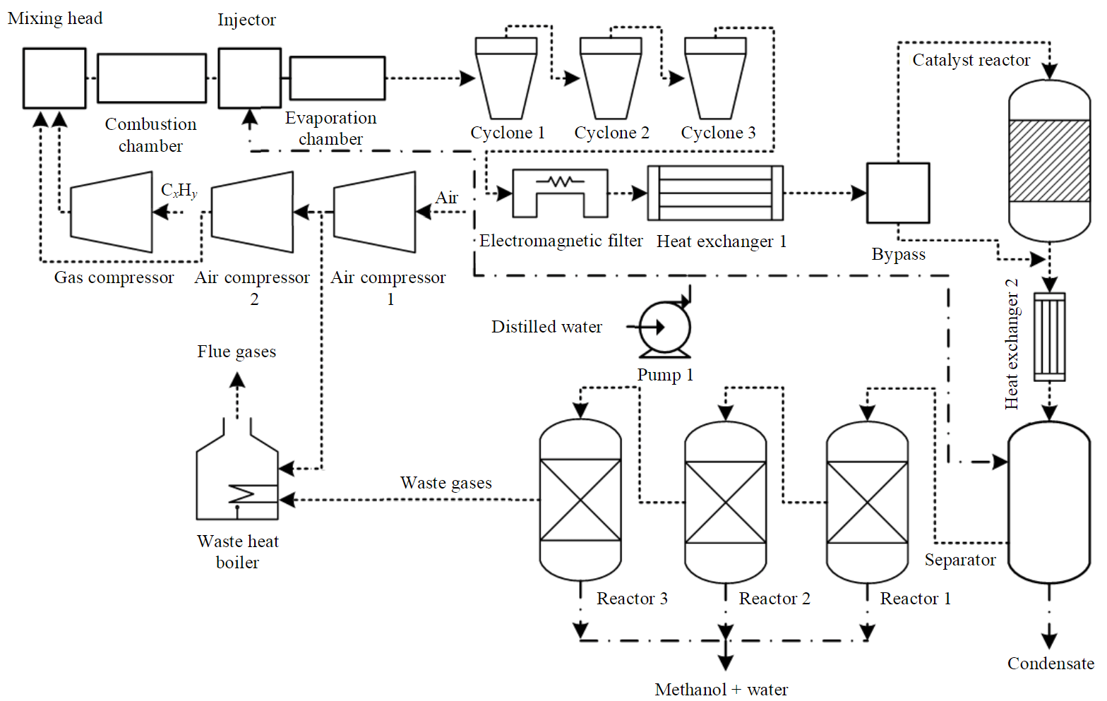
Fig.1. Methanol production process
The syngas produced by partial oxidation in the plant is cleaned from soot in three cyclones (1, 2 and 3 in Fig.1), an electromagnetic filter and heat exchanger 1. Part of the synthesis gas is directed via a bypass to the catalytic reactor, where a CO-shift reaction takes place with the addition of water and conversion of CO to CO2, due to which the molar fraction of H2 in the stream increases. The dried gas flows to heat exchanger 2 for cooling and then to a separator for separation of water from the flow. After the separator, the syngas is fed to reactor 1 (forming part of the cascade of reactors 1, 2 and 3) where methanol is produced in the presence of a catalyst. Due to ballast gases it is not feasible to use one recycling reactor. In the proposed scheme, three reactors are used to increase the percentage of conversion as there is a significant amount of nitrogen in the syngas. Methanol obtained in reactor 1 is directed to the heat exchanger where it is cooled down and goes to the separator for separation of unreacted syngas from obtained methanol and water. The methanol with water is collected in a tank, while the remaining syngas is routed to the second and third stages of the cascade to reactors 2 and 3. The unreacted gas is sent to the waste heat boiler, where it is afterburning and vented to the atmosphere via a filter system.
For various thermobaric conditions in the elements of a methanol production plant, it is not possible to select a ready-made solution, as the medium and process parameters will change not only when scaling the process, but also when changing the composition of the processed hydrocarbon gas depending on a variety of other characteristics. Taking this into account, elements of such turboexpanders have to be designed based on the specific conditions in order to realize the system.
The mechanical energy generated by the turboexpander is used to drive the compressor to supply air (oxidizer) to the mixer, after which the gases enter the reactor for further recuperation. The implementation of this scheme has significant limitations due to the small size of the unit, so the designed unit must have small mass-size characteristics and low operating costs.
To make efficient use of the waste gases (mass ratio of gas elements, %: 87.16 N2; 1.44 Н2; 5 CO2; 4.99 CO; 1.41 CH3OH), a turboexpander should be used, which has small mass-size characteristics and meets the specified parameters: inlet/outlet temperature – 260/139 °C; inlet/outlet pressure – 4.915/1.46 МPа; mass flow rate – 5112 kg/h; volume flow rate – 4768 nm3/h; power at the shaft – 200 kW.
Space must be used rationally and efficiently, as the main feature of the small-scale methanol plant to be developed is the small size and placement of many large components in a single 20ft container.
Considering the small dimensions and the required flow rate of the working medium, the inevitable increase of rotor rpm and circumferential velocities with a reduction of the rotor diameter has to be taken into account. With this condition in mind, it was decided to develop a centrifugal expander, which is a radial-axial vane machine. The choice of such a scheme is determined by simplicity and reliability of the centrifugal wheel. It can be manufactured in a single casting, which expands the operating rpm and possible heat drops, permissible according to durability characteristics.
As a result, the developed expander unit converts energy of waste gas expansion into mechanical energy of expander shaft rotation, which is used further to generate useful work. Waste gases are a mixture of nitrogen, hydrogen, carbon monoxide and dioxide, methanol. Parameters of the gas mixture were determined theoretically by calculations [26].
At the first design stage, the methods of A.N.Sherstyuk and A.E.Zaryankin, E.M.Bambushek, I.A.Sakun and V.I.Epifanov were selected. In the analysis of the proposed calculation methods and based on the analysis of articles [27, 28], the method of A.N.Sherstyuk and A.E.Zaryankin was chosen as the main one. Preliminary thermo gas-dynamic calculation of turbine expander is based on it. Number of blades was calculated by the methodology [27] and the minimum odd number was selected for minimization of friction losses and reduction of potential vibration of the rotor. Design diameter considering the small dimensions was set to D1 = 80 mm, At the same time the limiting value of circumferential velocity at the impeller inlet is u1max ∼ 500 m/s. Condition of circumferential velocity considers the durability characteristics of the materials, from which impellers are produced [29, 30]. The inlet angle β1 is set to 90° with regard to the requirement of shockless flow entry and manufacturability of the impeller blade design. To minimize the flow twist at the outlet of the impeller and reduce loss in the subsequent elements of the flow path, angle α2 is set to 90°. With regard to reduced flow velocity at the nozzle outlet λ ≤ 1 the specified degree of reactivity is ρ = 0.5.
Geometry construction of expander working stage
There are many methods for profiling the peripheral and sleeve rim of an impeller: circular, elliptical and parabolic curves, Bezier curves, etc., based on the research base and the experience of the designers. The meridional profile at this stage was constructed using circumferences. The thickness of the blades and the wedge angle were chosen so that the thickness of the narrow part of the wedge was not less than 1mm for technological reasons [31, 32]. The effect of impeller width on its efficiency was investigated in [28]. Insufficient width can cause breakaway zones under operating conditions, therefore, at this stage, the width was taken as B = 0.25D1. For preservation of the outlet angle constancy over entire profile height at an impeller outlet, the blade profile angle β2 changed by the law tg(β2)R2 = const [27].
According to preliminary calculations of the small-scaled methanol plant, the waste gas velocity at the reactor outlet before the expander is around 20-30 m/s. Considering the calculated degree of reactivity and velocity at the impeller inlet, it was decided to use a nozzle screen to achieve the required parameters and a set angle at the impeller inlet.
Construction of nozzle screen geometry
There is a variety of nozzle screen profiles in the form of blades and channel nozzles. Wing-shaped profiles with parallel adjacent walls are used for small-sized expander units. This is because with small blade sizes, their efficiency does not differ from the profiled ones, but design and fabrication is much easier [27, 29, 33]. For small inlet angles, the back wall is curved to achieve the optimum angle.
The basic geometric parameters of the profile and neck width are calculated based on the methodology proposed in [31] and taking into account the recommendations of [34, 35]. The curved area of the front wall is set by the radius of the circle. The constructed wing-shaped profile is shown in Fig.2.
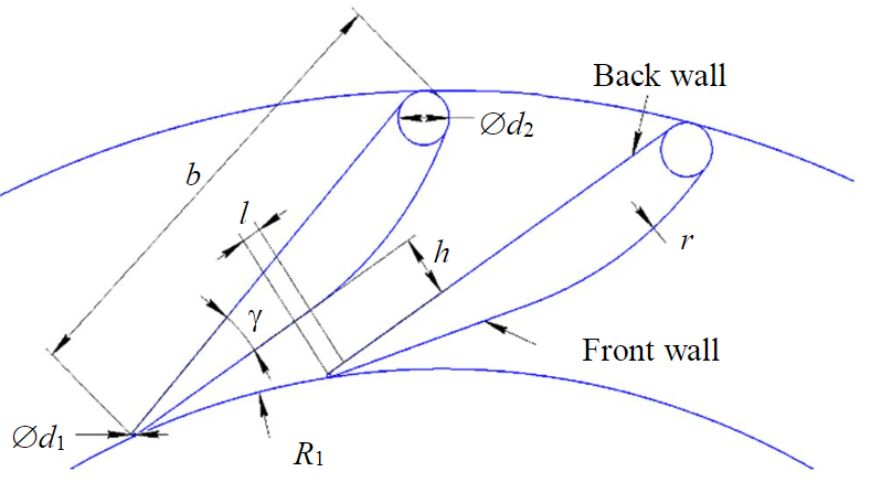
Fig.2. Profile of the designed nozzle screen: d1, d2 – diameters of rounding on outlet and inlet edges; R1 – internal radius, equal to the sum of impeller radius and gap; h – width of channel neck; r – radius of front wall rounding; – width of straight part of the neck; γ – angle of blade opening, defined as γ = 360/zb; zb – number of nozzle blades (taken as 24)
The optimum shape was selected by changing the blade length and neck section length. Neck length was selected to ensure the alignment of the velocity field at the outlet of the channel. Diameter of the outlet edge was set as small as possible to reduce the edge trace and was taken as 0.1 mm [33]. The calculation of such inlet elements is a challenging task due to the complex flow conditions [31, 32]. The methodology [32] was used to estimate preliminary dimensions.
Construction of turboexpander inlets
Inlet elements of expanders are usually designed as a ring or scroll with direct or angular fluid inlet in order to distribute the flow evenly around the circumference of the impeller [27]. The flow supply is made by a single pipe or several pipe connections. The way of flow supply in the inlet elements depends on the layout considerations and the required distribution of forces on the turbine impeller. Bladeless nozzle guide vanes, combining the functions of nozzle and inlet unit at low flow rates and values of reduced velocity, are also used [36].
Discussion of the results
The disadvantage of the scheme, which uses atmospheric air instead of pure oxygen, is the compression of air and hydrocarbon gas to 6 MPa that is the most energy-intensive part of the process. To improve the energy-efficiency of the process and reduce the carbon footprint of the synthesized products it is proposed to use several microturboexpander units with different characteristics and geometries to make efficient use of:
- excess waste gas pressure upstream of the waste heat boiler – to utilize the energy of the flow after the methanol synthesis reactors;
- flue gas pressure downstream of the waste heat boiler – after the flow is warmed up by the afterburning of the reaction gases, another microturbine can be placed;
- water vapour pressure in the high-temperature circuit – will make it possible to utilize excess high-potential heat energy;
- vapour phase pressure of low-boiling fluid in the low-temperature circuit – will recover excess low-potential thermal energy and cool the streams before separating the liquid phase (water, methanol).
Figure 3 shows the developed scheme for improving energy-efficiency and reducing the carbon footprint of the methanol production process. Fig.3, a shows the operation algorithm of turboexpander 1 and 2. The methanol, which is extracted from the streams coming out of three reactors in the cascade, is collected and used for field needs. The methanol does not need to be completely separated from the water for hydrate inhibition purposes. Waste gases, separated after the third reactor, are under significant overpressure (up to 5 MPa), which is used to drive turboexpander 1. The syngas remaining after passing through the reactor cascade and the first expander is then combusted in the waste heat boiler, which is a sealed vessel with an integrated ignition burner. In the burner, the waste gases are mixed with enriched compressed air, supplied from the air compressor 1. After the waste heat boiler, the flue gases are sent to the turboexpander 2 for the final stage of stream energy utilization. The flue gases are then discharged through filters to the atmosphere or to a CO2 capture plant (not shown in the scheme).
Figure 3, b shows the operation algorithm for turboexpanders 3 and 4. Water is used to remove excess heat generated after the high-temperature reactor on heat exchanger 1. The refrigerant (water) is circulated in the high-temperature circuit by means of a pumping station and the pressure at the inlet to each heat exchanger is regulated by means of control valves. After taking up the heat, the water is converted into steam, which rotates the turboexpander 3. Heat removal and steam condensation is carried out on a single refrigeration centre, which includes a low-boiling organic Rankine cycle circuit to recover the energy of the low-potential heat at the turboexpander 4. The low-boiling circuit is used to cool the technological flows upstream of the separators to separate water, methanol and syngas. At the same time, all turboexpanders in the developed scheme are used to drive generators for power production.
Analysis of calculation results on design of turbine in microturboexpander unit
Calculation was carried out in a dedicated software created for this purpose in Python 3. Application of this language is promising for further automation of calculations and automatic construction of elements in application software packages supporting scripts in this language.
Since the main angles are set for design considerations, and the angle β2 is determined by the calculation result from the condition α2 = 90, the set parameter remains α1. Its effect on the isoentropic efficiency of the turbine stage should be investigated. Since the calculation capacity is limited, it is necessary to simplify the calculation model. One option is to calculate only one blade with part of the flow area around it. In this case, the boundary areas of the flow are made periodic, allowing the calculation to be carried out with only one area.
Geometry of the nozzle blade was created in SolidWorks and then imported into ANSYS DesignModeler. Design mesh was built in the TubroGrid module (Fig.4). The number of cells in the mesh was ~510000. Verification calculation was performed in the CFX module.
The gas mixture was set as Pure Substance, with thermodynamic model being an ideal gas. Parameters of the mixture were set according to the reference books. The calculation has been carried out as a steady-state problem. Set boundary conditions are: inlet full temperature T*0 = 533 К and gas mixture flow rate G = 1.42 kg/s; outlet static pressure P1 = 2.817 MPa, predetermined from thermo gas-dynamic calculation results. SST-Menter was chosen as the turbulence model, as it is able to provide the necessary accuracy for such problems [37]. The calculation result is shown in Fig.5.
Zone of flow detachment is observed on the front wall at the transition to the neck area. To avoid such issues it is necessary to continue selecting a circumferential radius that allows a smoother flow transition along the profile curve, or to apply other curve methods such as a Bezier curve.
When the angle of flow to the nozzle is small, the back wall is replaced by a curve that provides a favourable flow path. Once the nozzle geometry is obtained, a joint calculation with the impeller is carried out (the same way is for the nozzle). Specified boundary conditions: inlet total temperature T*0 = 533 К and gas mixture flow rate G=1.42 kg/s; outlet static pressure P2 = 1.46 MPa.
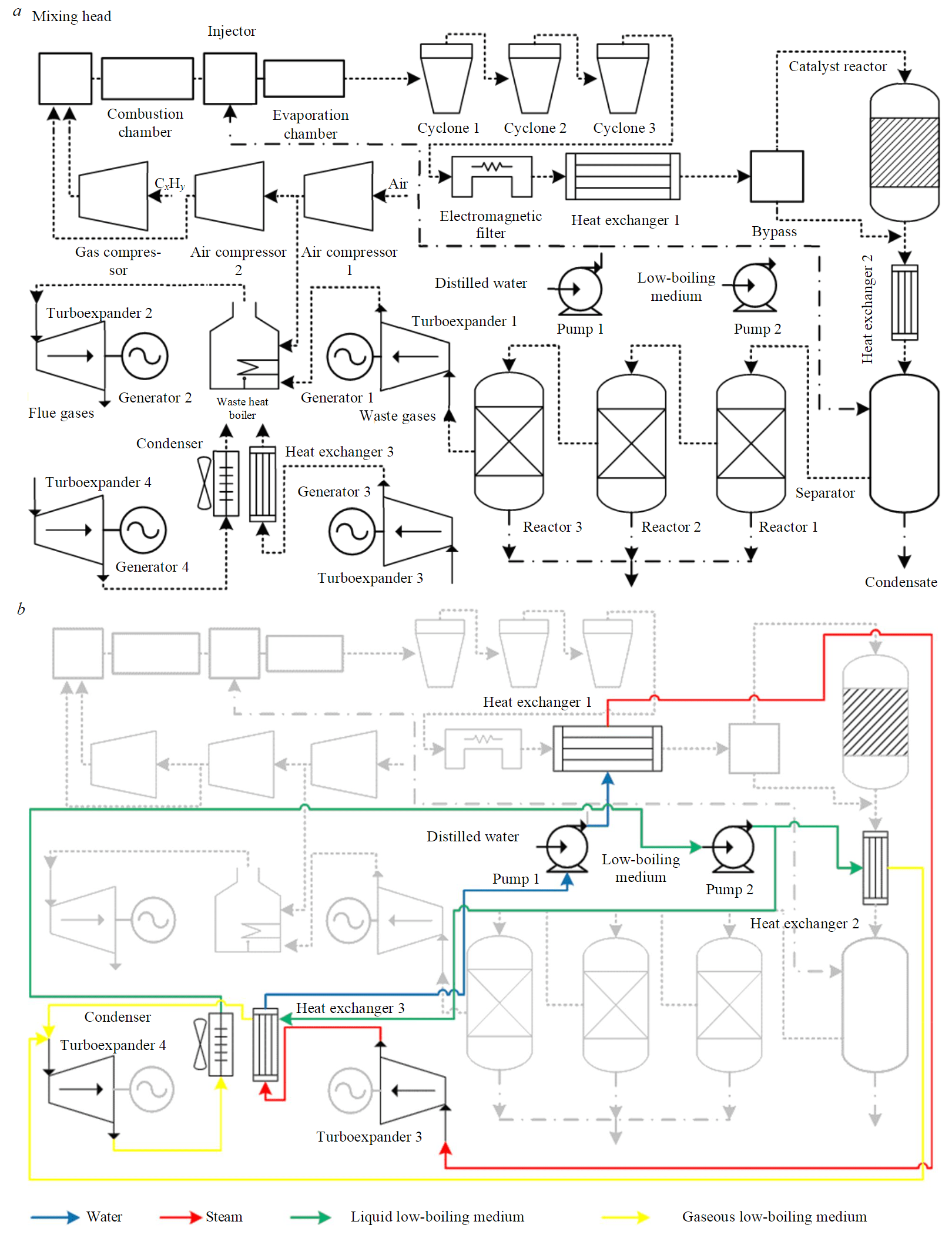
Fig.3. Scheme of material (а) and energy flows (b) in the energy utilization system of small-scale methanol production
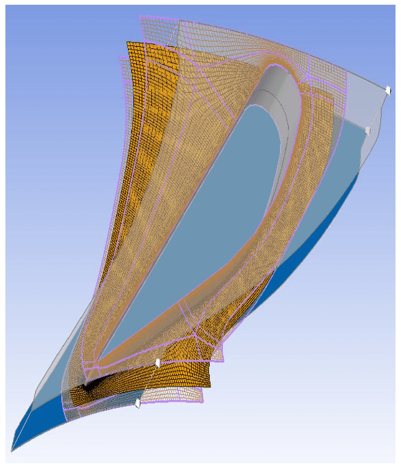
Fig.4. Calculation mesh in the inter-blade nozzle channel
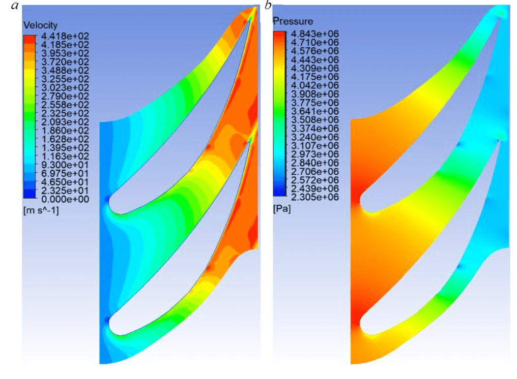
Fig.5. Fields of velocity (а) and pressure (b) in the nozzle channel
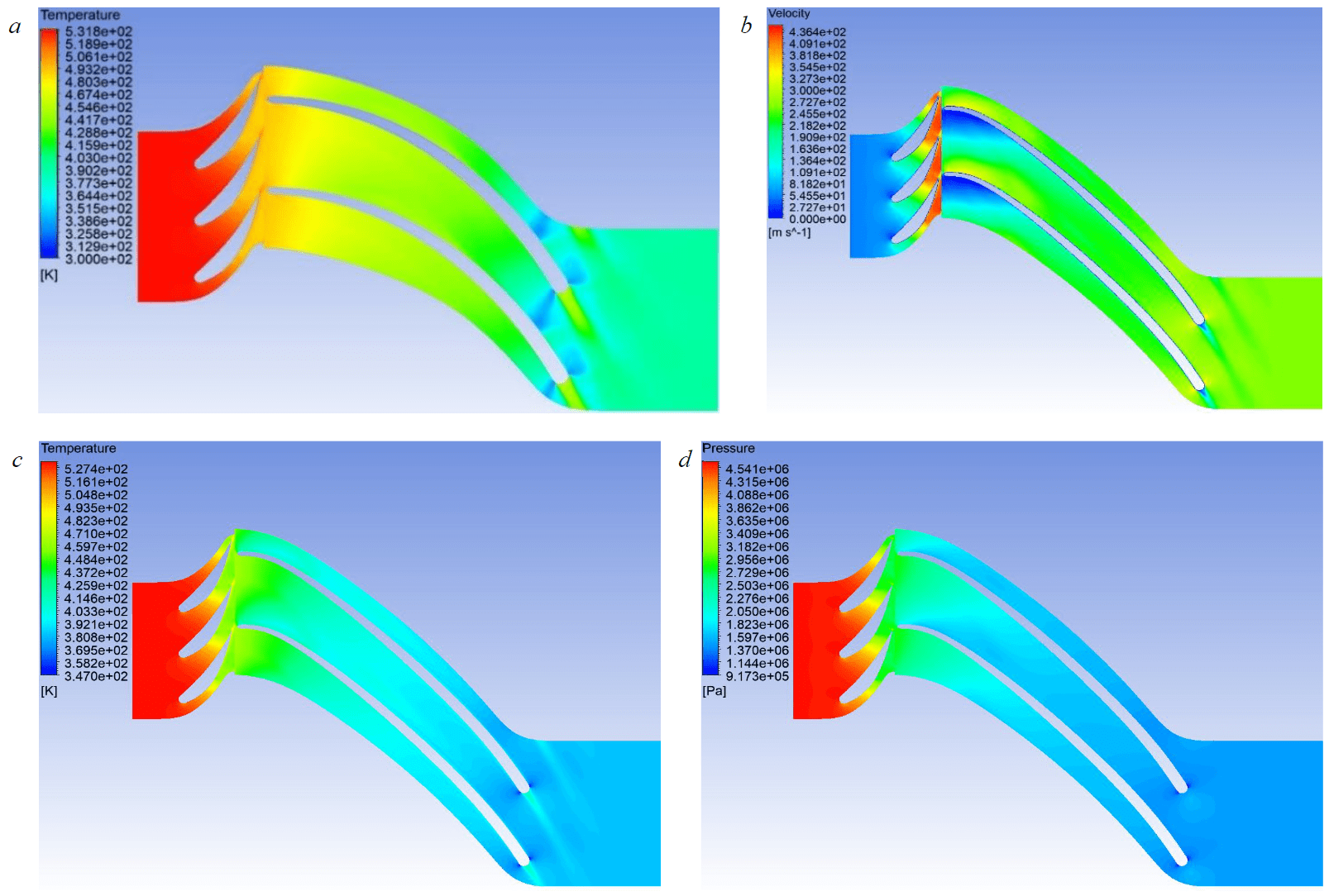
Fig.6. Fields of distribution for temperature (а), velocity (b), static temperature (c), static pressure (d)
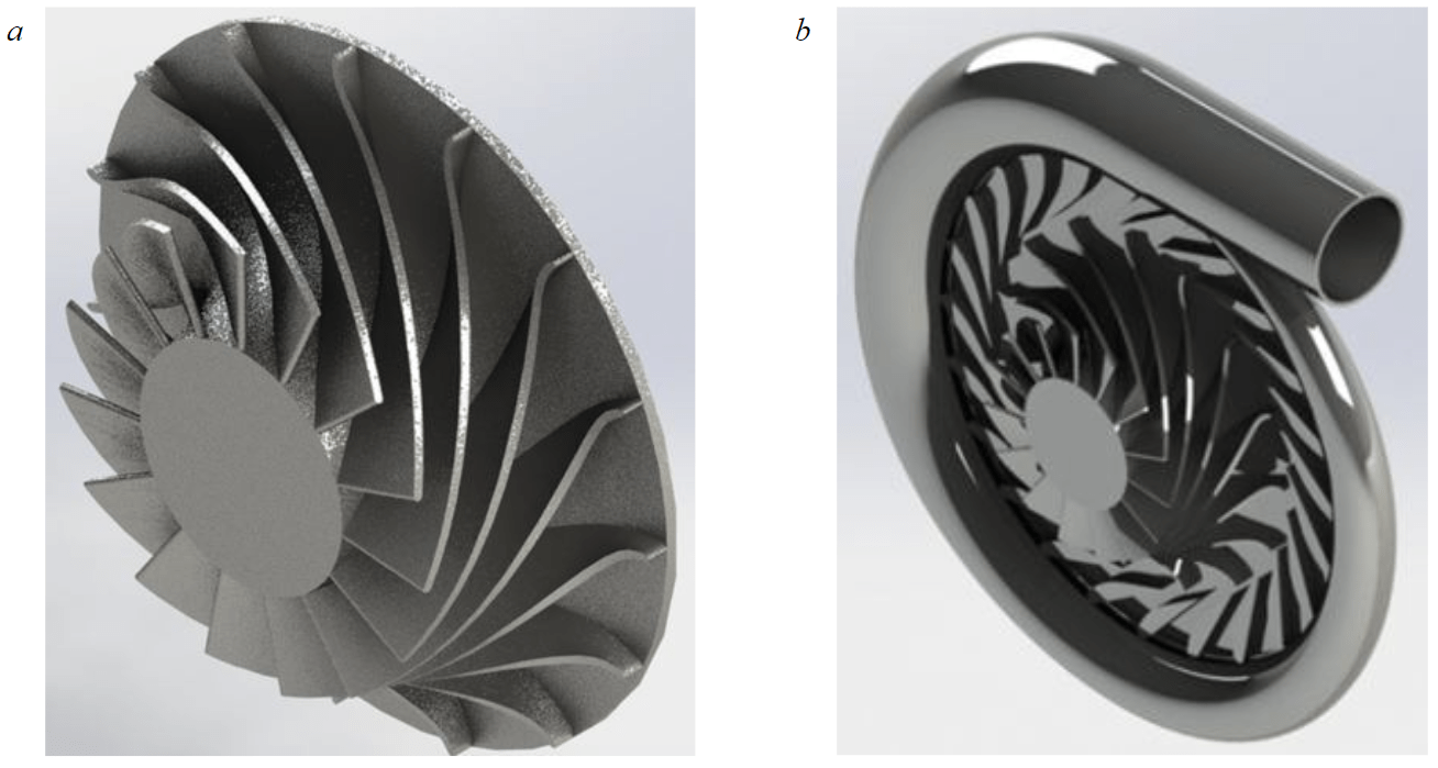
Fig.7. 3D-model of impeller (а) and a scroll with impeller (b)
When constructing the calculation model, the condition of approximate equality for the areas of the calculation parts at the nozzle outlet and the impeller inlet has to be fulfilled. The final calculation area is represented by 3 nozzle areas with two impeller areas. Number of cells per nozzle and impeller design area is approximately 1250000. As can be seen from the distributions in the Fig.6, the obtained impeller obeys the known physical models, taking into account the non-standard gas mixture. The turbine stage obeys the well-known laws of thermodynamics, the pressure and temperature drop and the velocity in the confusor channel increases.
From the graph α1 = 19° is selected, which corresponds to n = 89790 rpm; efficiency = 0.807. Following parameters of the impeller stage are obtained: D1 = 80 mm; α1 = 19°; β2 = 26°; N = 198.7 kW; efficiency = 0.807; Тout = 134.14 °C; u1 = 376 m/s; n = 89790 rpm; number of impeller blades – 15; degree of reactivity/radiality – 0.5/0.5.
The averaged parameters for the total pressure at the nozzle inlet, the static temperature at the impeller outlet and other parameters are calculated using the function calculator. Obtained results of numerical modeling: inlet pressure P0* = 4.65 MPa; outlet static temperature T2 = 399 K; absolute velocity at the impeller outlet c2 = 98.07 m/s; torque of the turbine shaft on the z-axis per blade M = 1.5 N·m; angle of flow outlet from the impeller – 64°.
Circumferential radii xc in the cross-sections and their corresponding angles Δν are: 23 mm/0°; 20.5/45; 18.8/90; 17.2/135; 15.2/180; 13.2/225; 10.6/270; 7.5/315; 0/360.
Impeller model and assembly view are shown in Fig.7. In order to estimate the dimensions of the unit from the results obtained, the geometry of the scroll and the assembly is constructed as a first approximation.
The developed turboexpander is supposed to be used to drive the shaft of an electric generator. However, the main problem with this solution is the high rotation speed of the turbine and the shaft of the electric generator. In order to ensure quality parameters of generated electric power, uncontrolled and active voltage rectifiers, as well as passive and active power filters of higher harmonics, are included in the structure of the power system. The generated electric power can be used to supply the auxiliary needs of the plant or for other purposes in the area where the system is located.
The proposed approach is based on the automation of the calculation and design of microturboexpanders developed specifically for the flow parameters and properties of the working medium. The resulting 3D models of expander elements can be printed on a 3D printer, and after machining they can be used in the expander generators (to use the excessive pressure of the waste and flue gases) of conventional and organic Rankine cycles with water and low-boiling medium.
Conclusion
The scheme of a small-scale hydrocarbon gas processing plant, which can be used for a wide range of tasks, is considered: utilization of low-pressure gas and APG; provision of methanol or synthetic liquid hydrocarbons to remote facilities. The scheme is enhanced with the addition of four microturboexpander generators, which will allow the process to be more efficient.
The main dimensions have been obtained and the optimum angle α1 has been determined based on the set characteristics of the inlet diameter and revolutions of the impeller. The next stage of the research will be to investigate and improve the aerodynamic characteristics of the developed nozzle and impeller, and to calculate in detail the feeder scroll.
The proposed methodology facilitates the calculation of design parameters for microturbines, taking into account the characteristics of the working medium, temperature, pressure and performance of the gas flow fed to them.
The development of microturbogenerators capable of operating with waste gases, water vapour and low-boiling fluids will improve the energy-efficiency of the process and reduce the carbon footprint of the products produced.
References
- Litvinenko V. The role of hydrocarbons in the global energy agenda: The focus on liquefied natural gas. Resources. 2020. Vol. 9. Iss. 5. N 59. DOI: 10.3390/resources9050059
- Ilinova A., Chanysheva A. Algorithm for assessing the prospects of offshore oil and gas projects in the Arctic. Energy Reports. 2020. Vol. 6. Supplement 2, p. 1349-1355. DOI: 10.1016/j.egyr.2019.11.110
- Litvinenko V.S., Dvoynikov M.V., Trushko V.L. Elaboration of a conceptual solution for the development of the arctic shelf from seasonally flooded coastal areas. International Journal of Mining Science and Technology. 2021. Vol. 6. Supplement 2, p. 504-509. DOI: 10.1016/j.ijmst.2021.09.010
- Schipachev A.M., Dmitrieva A.S. Application of the resonant energy separation effect at natural gas reduction points in order to improve the energy efficiency of the gas distribution system. Journal of Mining Institute. 2021. Vol. 248, p. 253-259. DOI: 10.31897/PMI.2021.2.9
- Feigin V.I., Braginskii O.B., Zabolotskii S.A. et al. A study of the status and prospects of trends in oil and gas processing, petroleum and gas chemistry industries in the Russian Federation. Moscow: Ekon-inform, 2011, p. 806 (in Russian).
- Tcvetkov P.S., Fedoseev S.V. Analysis of project organization specifics in small-scale LNG production. Journal of Mining Institute. 2020. Vol. 246, p. 678-686. DOI: 10.31897/PMI.2020.6.10
- Arutyunov V.S., Strekova L.N., Nikitin A.V. et al. Prospects of Conversion of Hydrocarbon Gases to Liquid Products Based On Nitrogen-Rich Synthesis Gas (Review). Petroleum Chemistry. 2019. Vol. 59. N 4, p. 370-379. DOI: 10.1134/S0965544119040029
- Leusheva E.L., Morenov V.A. Development of combined heat and power system with binary cycle for oil and gas enterprises power supply. Oil Industry. 2017. N 7, p. 104-106 (in Russian). DOI: 10.24887/0028-2448-2017-7-104-106
- The World Bank. URL: https://www.worldbank.org/en/programs/zero-routine-flaring-by-2030 (accessed 23.03.2022).
- Statistical Review of World Energy 2022. URL: https://www.bp.com/content/dam/bp/business-sites/en/global/corporate/pdfs/energy-economics/statistical-review/bp-stats-review-2022-full-report.pdf %20 (accessed 26.09.2022).
- Tsvetkov P., Cherepovitsyn A., Makhovikov A. Economic assessment of heat and power generation from small-scale liquefied natural gas in Russia. Energy Reports. 2020. Vol. 6. Supplement 2, p. 391-402. DOI: 10.1016/j.egyr.2019.11.093
- Iakovleva E., Belova M., Soares A. Allocation of potentially environmentally hazardous sections on pipelines. Geosciences. 2021. Vol. 11. Iss. 1, p. 1-11. DOI: 10.3390/geosciences1101000
- Tsvetkov P.S., Fedoseev S.V. Analysis of project organization specifics in small-scale LNG production. Journal of Mining Institute. 2021. Vol. 246, p. 678-686. DOI: 10.31897/PMI.2020.6.10
- Lishchiner I.I., Malova O.V., Maslennikov V.M. et al. Synthesizing Methanol from Nitrogen-Ballasted Syngas. Catalysis in Industry. 2010. Vol. 2. N 4, p. 368-373. DOI: 10.1134/S2070050410040112
- Sultanbekov R., Beloglazov I., Islamov S. et al. Exploring of the incompatibility of marine residual fuel: A case study using machine learning methods. Energies. 2021. Vol. 14. Iss. 24. N 8422. DOI: 10.3390/en14248422
- Loseva E., Lozovsky I., Zhostkov R., Syasko V. Wavelet Analysis for Evaluating the Length of Precast Spliced Piles Using Low Strain Integrity Testing. Applied Sciences. 2022. Vol. 12. Iss. 21. N 10901. DOI: 10.3390/app122110901
- Koteleva N., Loseva E. Development of an Algorithm for Determining Defects in Cast-in-Place Piles Based on the Data Analysis of Low Strain Integrity Testing. Applied Sciences. 2022. Vol. 12. Iss. 20. N 10636. DOI: 10.3390/app122010636
- Litvinenko V., Meyer B. Syngas Production: Status and Potential for Implementation in Russian Industry. Cham: Springer, 2018, p. 161. DOI: 10.1007/978-3-319-70963-5
- Ahmadi M., Alizadeh S.M., Tananykhin D. et al. Laboratory evaluation of hybrid chemical enhanced oil recovery methods coupled with carbon dioxide. Energy Reports. 2021. Vol. 7, p. 960-967. DOI: 10.1016/j.egyr.2021.02.005
- Guo Q., Ahmadi M.H., Lahafdoozian M. et al. A laboratory approach on the improvement of oil recovery and carbon dioxide storage capacity improvement by cyclic carbon dioxide injection. Energy Reports. 2021. Vol. 7, p. 1571-1580. DOI: 10.1016/j.egyr.2021.03.012
- Ostadi M., Paso K.G., Rodriguez-Fabia S. et al. Process Integration of Green Hydrogen: Decarbonization of Chemical Industries. Energies. 2020. Vol. 13. Iss. 18. N 4859. DOI: 10.3390/en13184859
- Morenov V., Leusheva E., Buslaev G. et al. System of Comprehensive Energy-Efficient Utilization of Associated Petroleum Gas with Reduced Carbon Footprint in the Field Conditions. Energies. 2020. Vol. 13. Iss. 18. N 4921. DOI: 10.3390/en13184921
- Turbodetandernye agregaty. URL: http://geliymash.ru/production/turbodetandernye-agregaty/ (accessed 23.03.2022).
- ROTOFLOW Turboexpanders. URL: https://www.rotoflow.com/product/turboexpanders (accessed 23.03.2022).
- Mikroturbiny CAPSTONE. URL: https://capstone.ru/#sphere (accessed 23.03.2022).
- Zagashvili Yu.V., Efremov V.N., Kuzmin A.M., Lischiner I.I. Complex for Obtaining Synthesis-Gas for Smalltonnage Production of Methanol. Oil and Gas Chemistry. 2017. N 1, p. 19-26 (in Russian).
- Kartashev A.L., Martynov A.A. Mathematical Modeling and Optimizationof Flow Structure in Francis Turbine Stage of Microturbine Power Plant. Bulletin of the South Ural State University. Ser. Mechanical Engineering Industry. 2015. N 3, p. 28-36 (in Russian).
- Passar A.V. Influence of a meridian contour form in a driving wheel on gas flow parameters in a radially-axial turbine of a gas-turbine plant. Bulletin of the Tomsk Polytechnic University. Geo Аssets Engineering. 2017. Vol. 328. N 9, p. 33-48 (in Russian).
- Karimi Noughabi A., Sammak S. Detailed Design and Aerodynamic Performance Analysis of a Radial-Inflow Turbine. Applied Sciences. 2018. Vol. 8. Iss. 11. N 2207. DOI: 10.3390/app8112207
- Huebner J., Kata D., Kusiński J. et al. Microstructure of laser cladded carbide reinforced Inconel 625 alloy for turbine blade application. Ceramics International. 2017. Vol. 43. Iss. 12, p. 8677-8684. DOI: 10.1016/j.ceramint.2017.03.194
- Rahbar K., Mahmoud S., Al-Dadah R.K. Development and experimental study of a small-scale compressed air radial inflow turbine for distributed power. Applied Thermal Engineering. 2017. Vol. 116, p. 549-583. DOI: 10.1016/j.applthermaleng.2017.01.100
- Baturin O.V. Blading of Radial-Axial Turbine Wheel Using Bezier Curve. Bulletin of Samara State Aerospace University named after Academician S.P.Korolev (National Research University). 2011. N 3-3 (27), p. 125-130 (in Russian).
- Grigorev V.A., Kalabukhov D.S., Radko V.M. Numerical Gas-Dynamic Simulation of Singlestage Centripetal Ultralow Power Turbine. Vіsnik dvigunobuduvannya. 2013. N 2, p. 118-124 (in Russian).
- Development of technical solutions to ensure creation of domestic highly efficient scalable oil-free turbogenerators for aviation and power generation in the 100 kW power class. URL: https://www.voenmeh.ru/science/results/technical-solutions (accessed 23.03.2022).
- Belousov A.E., Ovchinnikov E.S. Mathematical Modeling of the Operation of an Expander-Generator Pressure Regulator in Non-Stationary Conditions of Small Gas Pressure Reduction Stations. Mathematics. 2022. Vol. 10. Iss. 3. N 393. DOI: 10.3390/math10030393
- Lishchiner I.I., Malova O.V., Tolchinskii L.S. “Energosintop” modular energy technological plants. Gas chemistry: state and ways of development in the XXI century. Proceedings of Moscow Seminar on Gas Chemistry 2012-2013. Moscow: Izd. tsentr RGU nefti i gaza imeni I.M. Gubkina, 2014, p. 140 (in Russian).
- Piven V., Zagashvili I., Kuzmin A. Natural gas emissions capture on site by small-sized noncatalytic converter of Methane to Syngas – Methanol that emulates liquid rocket engine. 2nd International Conference on Petrochemical Engineering, 23-25 July 2018, Kuala Lumpur, Malaysia. Arch Pet Environ Biotechnol. 2018. Vol. 3. Iss. 3, p. 32. DOI: 10.29011/2574-7614-C1-005