Determination of suitable distance between methane drainage stations in Tabas mechanized coal mine (Iran) based on theoretical calculations and field investigation

Abstract
A large amount of gas is emitted during underground mining processes, so mining productivity decreases and safety risks increase. Efficient methane drainage from the coal seam and surrounding rocks in underground mines not only improves safety but also leads to higher productivity. Methane drainage must be performed when the ventilation air cannot dilute the methane emissions in the mine to a level below the allowed limits. The cross-measure borehole method is one of the methane drainage methods that involves drilling boreholes from the tailgate roadway to an un-stressed zone in the roof or floor stratum of a mined seam. This is the main method used in Tabas coal mine N 1. One of the effective parameters in this method is the distance between methane drainage stations, which has a direct effect on the length of boreholes required for drainage. This study was based on the measurement of ventilation air methane by methane sensors and anemometers placed at the longwall panel as well as measuring the amount of methane drainage. Moreover, in this study, the obtained and analyzed data were used to determine the suitable distance between methane drainage stations based on the cross-measure borehole method. In a field test, three borehole arrangements with different station distances in Panel E4 of Tabas coal mine N 1 were investigated. Then, the amounts of gas drained from these arrangements were compared with each other. The highest methane drainage efficiency was achieved for distances in the range of 9-12 m between methane drainage stations.
None
Introduction
The history of coal mining shows that the methane released from the rock mass to the longwall area has been responsible for numerous mining disasters (especially the methane hazards), which can cause very serious accidents as a result of methane and/or coal dust explosions. One way to control methane in underground coal mines is to drain methane [1-3]. Methane drainage is used in coal mines to reduce methane emission as well as to keep methane concentration during mining at a safe level [4, 5].
During underground coal mining, large volumes of gas are released from coal seams and gas-bearing strata above and below the mined seam [6-8]. Methane drainage must be performed when the ventilation air cannot dilute the methane emissions in the mine to a level below the allowed limits [9]. Methane drainage from roof and floor strata is the most effective method of controlling methane hazards as it ensures the reduction of methane emission into the working areas [10, 11].
The method that has proved to be very efficient is draining methane from rock mass and goaf area and transporting it to the surface through pipelines, using the suction of drainage station pumps. This method can prevent the released gas in the damaged roof and floor strata from emitting into the longwall mining goaf and working face area [12, 13]. A.A.Campoli et al. adopted this type of cross-measure borehole to control the longwall goaf gas, in which boreholes with a small diameter are drilled from the underground inseam roadway into the fractured overburden strata to prevent CH4 from entering the ventilation system of the coal mine [14].
For methane drainage, there are several methods, one of which is used depending on the mine conditions. One of these methods is the cross-measure borehole method. Several factors in this method affect the degassing efficiency, including the angle of the boreholes relative to the axis of the tailgate, the dip of the boreholes [15, 16], the height of the boreholes from the top of the coal seam, and the distance between methane drainage stations. Proper distance between methane drainage stations is one of the most important factors in increasing drainage efficiency. N.Szlazak and J.Swolkien examined the methane drainage efficiency and ventilation air methane (VAM) in Polish coal mines from 2006 to 2017. According to his findings, the average efficiencies of methane drainage and methane output from ventilation were 32.96 and 67.04 %, respectively. The average efficiencies of methane drainage and VAM in different years are presented in Table 1 [17, 18].
Table 1
Average efficiencies of methane drainage and VAM in different years in Poland coal mines [17, 18]
|
Efficiency, % |
Year |
Average |
|||||||||||
|
2006 |
2007 |
2008 |
2009 |
2010 |
2011 |
2012 |
2013 |
2014 |
2015 |
2016 |
2017 |
||
|
Methane drainage |
33.26 |
30.58 |
31.16 |
30.36 |
30.65 |
30.19 |
32.20 |
32.63 |
36.03 |
36.33 |
36.64 |
35.53 |
32.96 |
|
VAM |
66.74 |
69.42 |
68.84 |
69.64 |
69.35 |
69.81 |
67.80 |
67.37 |
63.97 |
63.67 |
63.36 |
64.47 |
67.04 |
N.Szlazak et al. examined the relationship between the efficiency of methane drainage and the type of ventilation in Polish coal mines from 2005 to 2015. Average methane drainage efficiency in longwall mining ventilation systems [19, 20]: with a U ventilation system 41.2 %; with a Y ventilation system 48.7 %; with a parallel gate road and u ventilation system 63.9 %. The lowest efficiency is 41 % related to a U ventilation system [19].
In order to understand the law of methane motion in the goaf zone and to provide theoretical da-ta for methane drainage boreholes, Y.Zhang et al. calculated the height of the goaf and fractured areas according to experimental relations by field experiment. The results of their observations showed that with increasing distance from the working face, the concentration of gas in the goaf increases. When the distance from the working face is less than 150 m, the change in gas concentration will be relatively stable. But if the distance is more than 150 m, the gas concentration increases sharply [7]. J.Qin et al. used computational fluid dynamics (CFD) simulations and found that the boreholes closer to the tailgate had higher gas emissions [21].
To determine the best position of the end of the gas drainage borehole, T.Li et al. performed a series of numerical simulations with UDEC software in the goaf area [22]. They controlled the dynamic change of gas concentration at different borehole heights based on field tests. The results showed that at different distances, there are four distinct distribution zones in the horizontal direction: the fracture zone of the main rock layer, the fracture channel production and development zone, the fracture channel maturity zone, and the fracture channel closure zone. In the vertical direction of the goaf floor, there are three characteristics of overburden: caving zone, fracture zone, and bending zone. Based on the field test, it was found that there are four stages of change in gas concentration in a borehole: the stable stage of gas, the initial change stage of gas, the gas fluctuation stage, and the restabilization stage of gas. They showed that the efficiency of gas drainage can be improved by combining the overburden caving laws in the design of gas drainage holes [22].
Different positions of methane drainage boreholes may produce different drainage results in coal mines. To investigate this possibility, X.Liu et al. proposed a 3D model, which covers three kinds of drill holes. The results showed that the drainage pattern with up and down boreholes not only yields methane with high purity for recycling but also can be used to control the methane concentration in the upper corner [23]. Many variables affect the goaf gas flow and borehole drainage efficiency, such as the gas release characteristics of gas sources, the heights of caved and fractured zones of the goaf, and the location of the drainage boreholes. Z.Qin et al. investigated how these variables influence the goaf gas flow patterns and borehole performances through CFD simulations. Simulation results showed that the gas drainage velocities around the perimeter of the panel goaf are higher than in the central goaf. Moreover, the location of the drainage borehole has a significant influence on the drai-nage performance. Boreholes located in the lower region of the fractured zone (20 m above the roof) can draw more methane than those located in the upper region of the fractured zone (70 m above the roof) and those located in the caved zone (2 m above the roof) [24].
This study aims to improve the gas drainage process, taking into account the distance between methane drainage stations, and the technical parameters of boreholes in the cross-measure borehole method.
The cross-measure boreholes drainage method is the most widespread methane drainage method used in underground coal mines. Cross-measure boreholes generally are drilled through multiple rock layers to the targeted gas-bearing strata. The boreholes can be drilled from the tailgate roadway in the roof and floor strata. The placement of drainage boreholes in the longwall is dependent on the applied system of exploitation and ventilation [25, 26]. Different methods of methane drainage with cross-measure boreholes in the longwall extraction system according to the ventilation type are as follows.
Cross-measure methane drainage method with U ventilation system. In this system, the air is supplied from the main gate, and after passing through the face line, it leaves the tailgate. The drai-nage boreholes in this system are drilled from the tailgate roadway and are eliminated after the advancement of working face [20]. The decisive factor that determines the level of methane capture and therefore the efficiency of methane drainage is the large number of boreholes simultaneously connected to the drainage system with negative pressure [25]. The angle of the borehole from the tailgate roadway generally ranges from 20 to 60°. In addition, the inclination and spacing of boreholes largely are determined by the gas content in the roof and floor strata as well as other geomechanically parameters related to the borehole stability [27, 28]. In this method, drainage boreholes are drilled with a length of 60-80 m, every 20-50 m from the tailgate roadway [29, 30].
Cross-measure methane drainage method with Y ventilation system
In this system, intake air is delivered into a longwall face through the main gate roadway and tailgate roadway, and return air flows through the tailgate roadway along the goaf. This system is used for longwalls with a high predicted level of methane content. Drainage boreholes in this system are drilled from a tailgate roadway, and they have to take out methane from places of greatest emission. Boreholes located 50-200 m behind the longwall face work most effectively. In this case, the methane drainage efficiency is usually greater than that of a U system [31, 32].
Cross-measure methane drainage method with a parallel tailgate roadway
This system, in addition to the main gate roadway, has two parallel tailgate roadways that are separated from each other by chain pillars. This system is used in longwalls with a high prediction of methane emission. Intake air is supplied to the longwall face through two roadways: the main gate roadway and the tailgate roadway; return air flows through the second tailgate roadway. The drainage boreholes in this system are drilled from the higher parallel roadway towards the lower one. Boreholes located 50-200 m behind the longwall face are the most effective [20, 31].
The Parvadeh Coal Mine N 1 is located in Tabas County, South Khorasan province, Iran. Five main coal seams have been explored (B1, B2, C1, C2, and D) at the coal deposit, and currently C1 is being worked.
To date, seven panels have been extracted. The working face of this study is Panel E4. Tabas Coal Mine adopts a “U-type” ventilation system for air supply. Methane drainage started from Panel E3, and Panel E4 is currently being drained. In this system, air is supplied via the bottom road and passes through the longwall. Drainage boreholes are drilled from the tailgate roadway and are liquidated as the exploitation front moves on.
Technical data of the drilling rig [34]: maximum drilling depth of a hole 120 m; full section drilling diameter 59-143 mm; drilling angle 90°… –90°. Technical data of methane drainage boreholes in Tabas coal mine [34]: borehole diameter 76 mm; borehole length 26-100 m (average 47); angle of the borehole from the axis of the tailgate onto the longwall face 18-45 (average 35); inclination of the borehole 10-38 degree (average 16). Physical and chemical characteristics of the coal in Tabas coal mine: permeability 1.9·10–12m2; porosity 1.9-7.8 %; density 1.6 kg/m3; ash 36 %; sulfur 2 %; volatile substances 15 %; moisture 0.9 %.
Methods and materials
In Tabas mechanized coal mine, methane drainage started from Panel E3. The length of Panel E3 is 1235 m, the average production speed is 3.9 m/d and the average daily production is 2448 t. The longwall retreat system and U ventilation system are commonly used. The drainage system in the mine uses cross-measure boreholes. Figure 1 shows the methane drained in m3/min during 42 weeks in the beginning of Panel E3. These details on Panel E3 were collected from 12.05.2018 to 01.03.2019. The average methane drainage during this period in Panel E3 was 6.6 m3/min per week, and the methane drainage efficiency was low. The total length of methane drainage boreholes drilled in these 42 weeks in Panel E3 was 11530 m, and the average length of methane drainage boreholes was 72.7 m. The number of boreholes drilled in Panel E3 was 159, and the distance between methane drainage stations in Panel E3 varied between 18 and 22 m.
The technical parameters of drainage boreholes are as follows: The average angle of the boreholes from the axis of the tailgate roadway was 38 degrees and the average inclination of the borehole was 16.09°.
The methane drainage efficiency was low in Panel E3, so it was decided to make changes in the arrangement of the boreholes and the distance between the drainage stations in Panel E4. Accor-dingly, various arrangements of stations in the mine were implemented. To increase the methane drainage efficiency, we decided to make changes in the distance between methane drainage stations and the length of methane drainage boreholes. For this purpose, we performed the following field test in Panel E4. The average production speed in Panel E4 was 3.4 m/day and the average daily production was 2209 t.
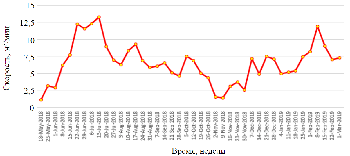
Fig.1. Methane drained in Panel E3
The analysis was performed to evaluate the change in the amount of methane captured by drai-nage and the efficiency of this process in relation to the effect of distance between the stations in Panel E4. We implemented three patterns of drilling with different distances between stations in Panel E4 to obtain the appropriate distance between methane drainage stations.
This field test was conducted on three groups: groups A, B, and C. Group A consisted of 11 methane drainage stations (1-11), and in each station, four boreholes were drilled. The distance between the stations was 18 to 22 m. Group B consisted of eight methane drainage stations (12-19), and in each station, six boreholes were drilled. The distance between the stations in this group was 9 to 12 m. Group C consisted of 16 stations (20-35), and in each station, four boreholes were drilled with a distance in the range of 9 to 12 m. The drilling layout is shown in Fig.2.
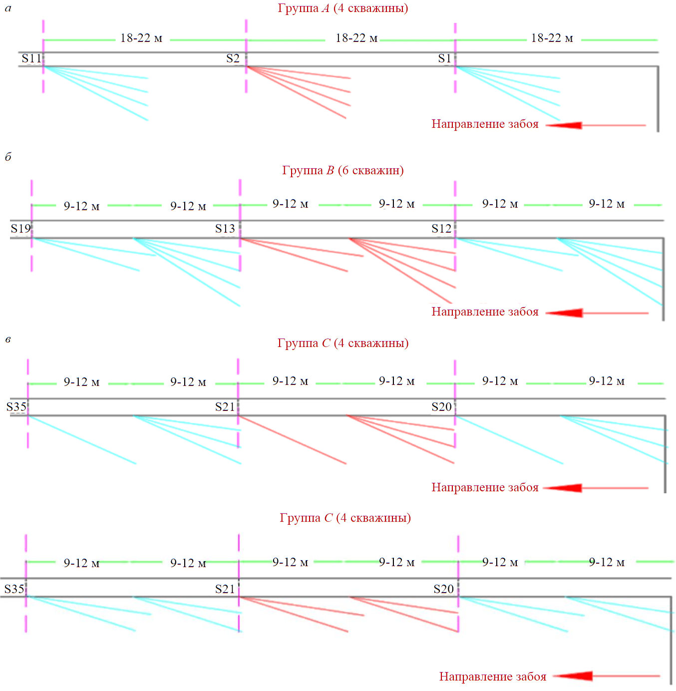
Fig.2. Distance between methane drainage stations in groups A (а), B (b), and C (c)
The total length of methane drainage boreholes drilled in these 42 weeks in Panel E4 was 5584 m, and the average length of methane drainage boreholes was 36.2 m. The number of boreholes drilled in Panel E4 was 154. The technical parameters of the drainage boreholes in this panel are as follows: The average angle of the borehole from the axis of the tailgate roadway was 36° and the average inclination of the borehole was 17.8°.
This study was conducted from 07.02.2020 to 20.11.2020 in Panel E4. The length of the studied panel was 1325 m, and we performed this field test in the first 466 m of the panel. We used methane sensors and anemometers placed in the air return entry (tailgate) to collect the data from the ventilated air methane. During this time, the length of the extracted part of the longwall panel reached approximately 466 m.
The methodology of methane measurements in the methane drainage pipeline network in each station was as follows:
- The amount of methane mixture is calculated according to the following formula for measuring the orifice [28]
where A – orifice plate factor; ΔP – pressure difference, mm H2O; P – absolute pressure, mm Hg; P = B + P1 – P2; B – barometric pressure, mm Hg; P1 – pressure related to depth, mm Hg; P2 – the size of depression, mm Hg; S – relative gas density; T – gas temperature (primary rock mass or directly from the installation; T = t + 273 °C.
- The amount of captured methane is calculated by as follows:
where CCH4 – methane concentration in the pipeline, %.
The distance between stations and the amount of gas drained from each station are presented in Table 2.
Table 2
Distance between stations and the amount of gas drained in Panel E4
|
Number of Station |
Number of Boreholes |
Distance between stations, m |
Gas drained, m3 |
Group |
|
1 |
4 |
20 |
69832 |
A |
|
2 |
4 |
18 |
53258 |
A |
|
3 |
4 |
18 |
68916 |
A |
|
4 |
4 |
20 |
99568 |
A |
|
5 |
4 |
18 |
49634 |
A |
|
6 |
4 |
22 |
100205 |
A |
|
7 |
4 |
18 |
102327 |
A |
|
8 |
4 |
20 |
107087 |
A |
|
9 |
4 |
22 |
94614 |
A |
|
10 |
4 |
18 |
114190 |
A |
|
11 |
4 |
18 |
114611 |
A |
|
12 |
6 |
9 |
142370 |
B |
|
13 |
6 |
10 |
161363 |
B |
|
14 |
6 |
12 |
175522 |
B |
|
15 |
6 |
10 |
118089 |
B |
|
16 |
6 |
9 |
84471 |
B |
|
17 |
6 |
9 |
141219 |
B |
|
18 |
6 |
12 |
186249 |
B |
|
19 |
6 |
9 |
182988 |
B |
|
20 |
4 |
12 |
134113 |
C |
|
21 |
4 |
11 |
118972 |
C |
|
22 |
4 |
9 |
193711 |
C |
|
23 |
4 |
10 |
157162 |
C |
|
24 |
4 |
10 |
149109 |
C |
|
25 |
4 |
9 |
120309 |
C |
|
26 |
4 |
9 |
246391 |
C |
|
27 |
4 |
11 |
223871 |
C |
|
28 |
4 |
11 |
155135 |
C |
|
29 |
4 |
9 |
253248 |
C |
|
30 |
4 |
10 |
162392 |
C |
|
31 |
4 |
10 |
160369 |
C |
|
32 |
4 |
9 |
142357 |
C |
|
33 |
4 |
9 |
117161 |
C |
|
34 |
4 |
10 |
106332 |
C |
|
35 |
4 |
11 |
193997 |
C |
The calculation of methane efficiencies from drainage and ventilation:
Results and discussion
The results of the statistical analysis are shown in Fig.3, 4. In the beginning phase of panel production (30-239 m into the longwall panel consisting of boreholes of group A), the amounts of methane captured by drainage in the beginning phase of production were from 2.8 to 6.5 m3/min with an average of 4.1 m3/min. The values of VAM were in the range of 16.6 to 25.7 m3/min, with an average value of 20.4 m3/min, and absolute methane ranged from 19.9 to 29.12 m3/min with an average of 24.4 m3/min.
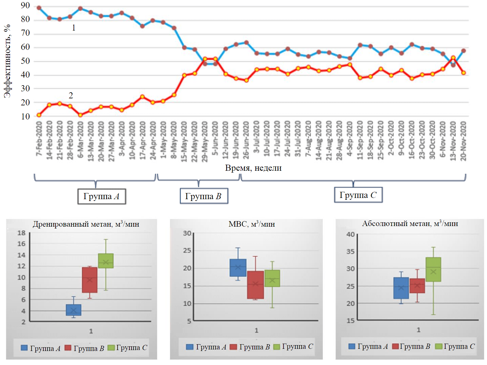
Fig.3. Changes in the amount of drained methane, VAM, and absolute methane in each group 1 – ventilation air methane efficiency; 2 – methane drainage efficiency
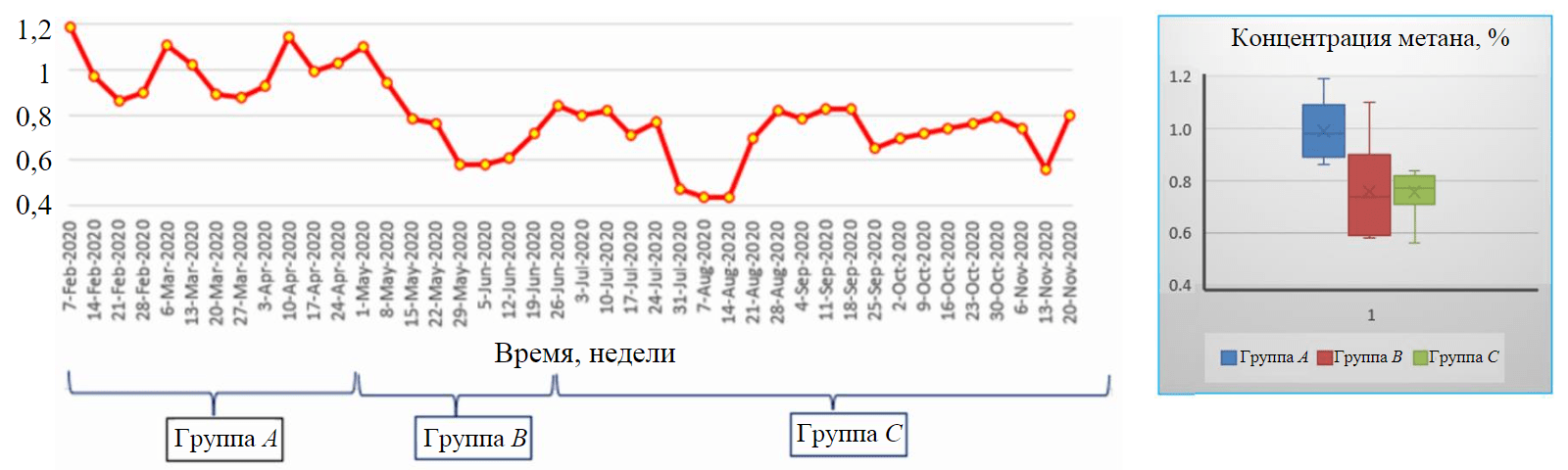
Fig.4. Methane concentration in tailgate roadway (return airway, Panel E4)
For 240 to 323 m into the longwall panel consisting of boreholes in group B, the amounts of methane captured by drainage in this phase of production were from 6.3 to 12 m3/min with an average of 9.5 m3/min. The values of VAM were in the range of 11.1-23.4 m3/min with an average value of 15.7 m3/min, and absolute methane ranged from 20.4 to 29.7 m3/min with an average of 25.2 m3/min.
For 324 to 466 m into the longwall panel consisting of boreholes in group C, the amounts of methane captured by drainage in this stage were from 7.2 to 16.8 m3/min with an average of 12.3 m3/min. The values of VAM were in the range of 8.8-21.9 m3/min with an average value of 16.6 m3/min, and the absolute methane ranged from 16.7 to 36.2 m3/min with an average of 29 m3/min.
The efficiencies of methane drainage and VAM are shown in Fig.3. The lowest efficiency of methane drainage was when the distance between methane drainage stations was in the range of 18-22 m. The highest average methane drainage efficiency, reaching up to 52.7 %, was achieved for the time interval of group C with the same number of boreholes.
Figure 4 shows the methane concentration at the tailgate roadway in the time intervals of groups A, B, and C. It is clear that although the methane drainage stations with distances in the range of 9-12 m keep the methane concentration low in the tailgate roadway, the distances in the range of 18-22 m lead to increasing return methane level. Groups B and C with distances of stations between 9 and 12 m keep the return methane in the tailgate roadway at a lower level than group A with distances of stations between 18 to 22 m.
Fig.5 compare different parameters of drainage boreholes in Panels E3 and E4, respectively. As shown in these figure, the number of boreholes drilled during the first 42 weeks in Panel E3 was 159, while the number of boreholes drilled in Panel E4 was 154. Moreover, the average lengths of boreholes drilled in Panels E3 and E4 were 72.70 and 36.20 m, respectively.
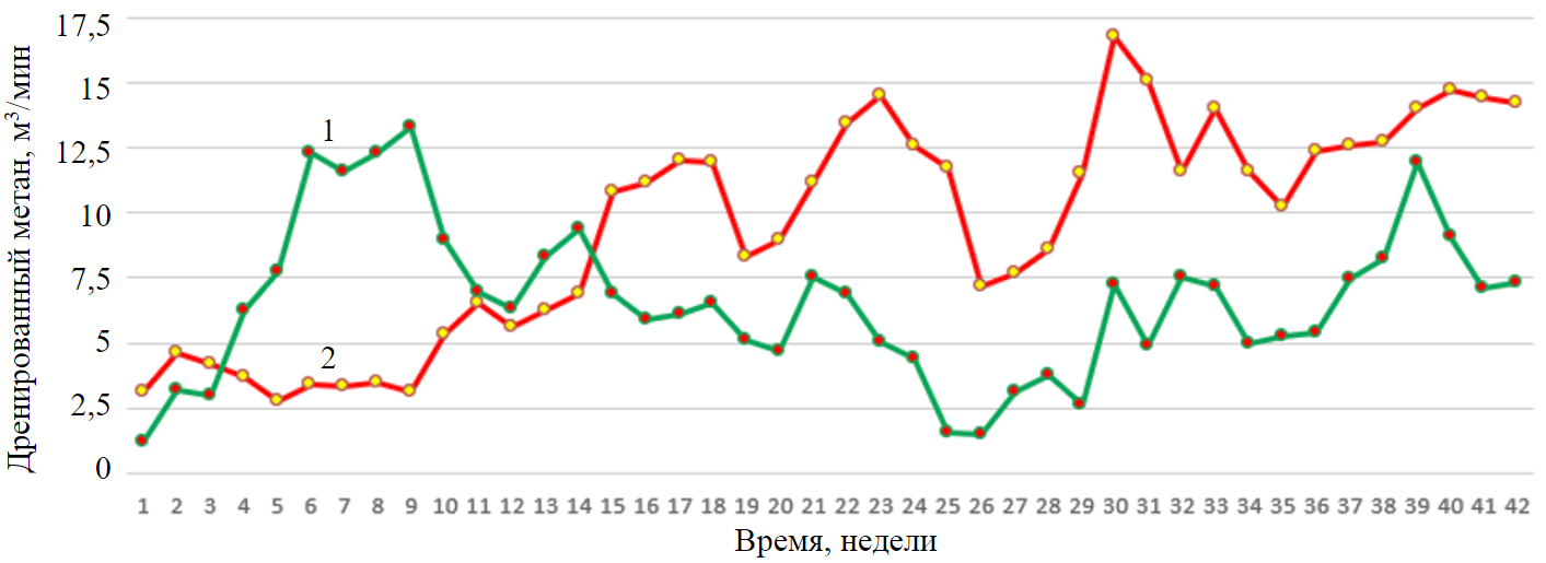
Fig.5. Comparison of methane drained from Panels E3 and E4 1 – Panel Е3; 2 – Panel Е4
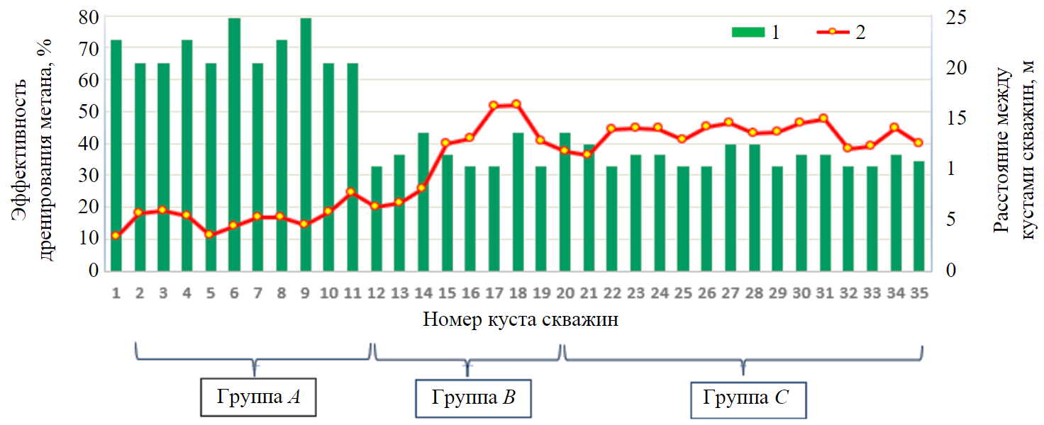
Fig.6. Effect of distance between methane drainage stations on the methane drainage efficiency 1 – distance between stations; 2 – methane drainage efficiency
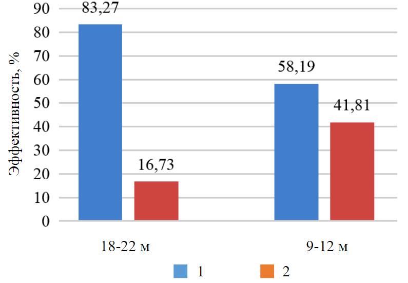
Fig.7. Average methane drainage and VAM efficiencies 1 – ventilation air methane efficiency; 2 – methane drainage efficiency
The total lengths of the boreholes drilled in Panels E3 and E4 were 11530 and 5584 m, respectively. However, the amount of methane drained from Panel E4 was higher than that from Panel E3.
Analysis of results shows that the amount of methane drained from Panel E3 was higher than that from Panel E4 during weeks 4 to 14 for the following reasons: The rates of face advance in Panels E3 and E4 were respectively 24 and 18 m per week. The total lengths of boreholes during this period in Panels E3 and E4 were 2323 and 1110 m, respectively. The average lengths of the boreholes during this period in Panels E3 and E4 were 68 and 34 m, respectively. The number of boreholes drilled during this period in Panels E3 and E4 were 34 and 32, respectively.
Fig.6 and 7 show the field test results. According to these results, when the distances between methane drainage stations were in the range of 18-22 m (Group A), the methane drainage efficiencies were between 10 and 25 %. However, when the distance between stations was reduced, the efficiency reached about 40 % and in some cases about 50 % (Groups B and C).
Conclusion
Effective methane drainage in underground coal mines not only improves safety but also increases production. This study aimed to improve the gas drainage process, taking into account the distance between drainage stations in the cross-measure borehole method. The efficiency of a methane drainage system can be determined through a detailed analysis of methane emissions in longwall production panels. In this study, the highest efficiency of methane drainage was observed when the distances between stations were in the range of 9-12 m. The results showed that the efficiency of methane drainage was higher when the distances between stations were in the range of 9-12 m with the arrangement of boreholes 3-1, or 2-2 compared to when the distances between the stations with 4 boreholes were in the range of 18-22 m.
References
- Borowski M., Kuczera Z. Comparison of Methane Control Methods in Polish and Vietnamese Coal Mines. E3S Web of Conferences. 2018. Vol. 35. N 01004. DOI: 10.1051/e3sconf.20183501004
- Best Practice Guidance for Effective Methane Drainage and Use in Coal Mines, Ece Energy. Series N 31. United Nations, New York and Geneva, 2010, p. 86.
- Rahimi Sh., Ataee-pour M., Madani H., Aminossadati S.M. Investigating the impact of gas emission uncertainty on airflow distribution in an auxiliary ventilation system using CFD and Monte-Carlo simulation. Building and Environment. 2021. Vol. 204. N 108165, p. 1-10. DOI: 10.1016/j.buildenv.2021.108165
- Szlązak N., Swolkień J. The Effectiveness of the Methane Drainage of Rock-Mass With AU Ventilation System. Archives of Mining Sciences. 2016. Vol. 61. N 3, p. 617-634. DOI: 10.1515/amsc-2016-0044
- Dzhioeva A.K., Brigida V.S. Spatial non-linearity of methane release dynamics in underground boreholes for sustainable mining. Journal of Mining Institute. 2020. Vol. 245, p. 522-530. DOI: 10.31897/PMI.2020.5.3
- Saghafi A., Pinetown K.L. A new method to determine the depth of the de-stressed gas-emitting zone in the under burden of a longwall coal mine. International Journal of Coal Geology. 2015. Vol. 152. Part A, p. 156-164. DOI: 10.1016/j.coal.2015.09.008
- Yong Zhang, Xibin Zhang, Chunyuan Li et al. Methane moving law with long gas extraction holes in goaf. Procedia Engineering. 2011. Vol. 26, p. 357- 365. DOI: 10.1016/j.proeng.2011.11.2179
- Chenlin Wang, Xiaodong Zhang. Experimental study on the fracture distribution characteristics of the overlying strata in an abandoned gob. Research square. 2021. DOI: 10.21203/rs.3.rs-992837/v1
- Krause E., Skiba J. Formation of methane hazard in longwall coal mines with increasingly higher production capacity. International Journal of Mining Science and Technology. 2014. Vol. 24. Iss. 3, p. 403-407. DOI: 10.1016/j.ijmst.2014.03.020
- Hosseini A., Najafi M. Determination of Methane Desorption Zone for the design of drainage boreholes Pattern (Case Study: E4 Panel of Tabas Mechanized Coal Mine, Iran). Rudarsko-geološko-naftni zbornik. 2021, p. 61-75. DOI: 10.17794/rgn.2021.1.6
- Skotniczny P. Three-dimensional numerical simulation of the mass exchange between longwall headings and goafs, in the presence of methane drainage in a U-type ventilated longwall. Archives of Mining Sciences. 2013. Vol. 58. N 3, p. 705-718. DOI: 10.2478/amsc-2013-0049
- Guorui Feng, Ao Zhang, Shengyong Hu et al. A Method to Accurately Determine the Methane Enrichment Zone of a Longwall Coal Mine. Geofluids. Vol. 2019. N 2438075, p. 1-10. DOI: 10.1155/2019/2438075
- Karacan C.Ö., Diamond W.P., Schatzel S.J. Numerical analysis of the influence of in-seam horizontal methane drainage boreholes on longwall face emission rates. International Journal of Coal Geology. 2007. Vol. 72. Iss. 1, p. 15-32. DOI: 10.1016/j.coal.2006.12.007
- Campoli A.A., Cervik J., Schatzel S.J. Control of Longwall Gob Gas With Cross-Measure Boreholes (Upper Kittanning Coalbed): Report of investigations / United States Department of Interior, Bureau of Mines. N 8841. Bureau of Mines, 1983, p. 1-17.
- Brigida V.S., Golik V.I., Dmitrak Yu.V., Gabaraev O.Z. Ensuring Stability of Undermining Inclined Drainage Holes During Intensive Development of Multiple Gas-Bearing Coal Layers. Journal of Mining Institute. 2019. Vol. 239, p. 497-501. DOI: 10.31897/PMI.2019.5.497
- Pan Wei, Changwen Huang, Xuelong Li et al. Numerical simulation of boreholes for gas extraction and effective range of gas extraction in soft coal seams. Energy Science and Engineering. 2019, p. 1-17. DOI: 10.1002/ese3.377
- Swolkien J. Utilizing of Methane from Polish Hard Coal Mines. Journal of Energy and Power Engineering. 2015. Vol. 9, p. 149-160. DOI: 10.7265/1934-8975/2015.02.004
- Szlazak N., Obracaj D., Swolkien J. Enhancing Safety in the Polish High-Methane Coal Mines: An Overview. Mining,Metallurgy & Exploration. 2020. Vol. 37, p. 567-579. DOI: 10.1007/s42461-020-00190-0
- Szlazak N., Obracaj D., Swolkień J. Methods of Methane Control in Polish Coal Mines. Proceedings of the 11th International Mine Ventilation Congress. Beijing, China: Jointly published with Science Press, 2018, p. 292-307. DOI: 10.1007/978-981-13-1420-9_25
- Szlązak N., Borowski M., Obracaj D. et al. Selected issues related to methane hazard in hard coal mines. Kraków: AGH University of Science and Technology Press, 2014, p. 148.
- Qin Johnny, Qu Qingdong, Guo Hua. CFD simulations for longwall gas drainage design optimization. International Journal of Mining Science and Technology. 2017. Vol. 27. Iss. 5, p. 777-782. DOI: 1016/j.ijmst.2017.07.012
- Tengteng Li, Bing Wu, Baiwei Lei. Study on the Optimization of a Gas Drainage BoreholeDrainage Horizon Based the Evolution Characteristics of Mining Fracture. Energies. 2019. Vol. 12 (23). N 4499. DOI: 10.3390/en12234499
- Xingkui Liu, Shuzhao Yang. Three-dimensional numerical simulation of methane drainage by high-level drill holes in a lower protective coal seam with a “U” type face. International Journal of Coal Science & Technology. 2014. Vol. 1 (4), p. 434-440. DOI: 10.1007/s40789-015-0053-6
- Zongyi Qin, Liang Yuan, HuaGuo, Qingdong Qu. Investigation of longwall goaf gas flows and borehole drainage performance by CFD simulation. International Journal of Coal Geology. 2015. Vol. 150-151, p. 51-63. DOI: 10.1016/j.coal.2015.08.007
- Berger J., Markiewicz J., Dolega T. Influence of distance of exploitational front from drainage boreholes on their efficiency with use the U ventilation system. Archives of Mining Sciences. 2010. Vol. 55. N 3, p. 561-571.
- Yangchun Han, Jiulong Cheng, Qisong Huang et al. Prediction of the height of overburden fractured zone in deep coal mining: Case study. Archives of Mining Sciences. 2018. Vol. 63 (3), p. 617-631. DOI: 10.24425/123687
- Whittles D.N., Lowndes I.S., Kingman S.W. et al. The stability of methane capture boreholes around a long wall coal panel. International Journal of Coal Geology. 2007. Vol. 71. Iss. 1-3, p 313-328. DOI: 10.1016/j.coal.2006.11.004
- Yuanyuan Xing, Feifei Zhang. Optimizing borehole spacing for coal seam gaspre-drainage. Journal of Geophysics and Engineering. 2019. Vol. 16. Iss. 2, p. 399-410. DOI: 10.1093/jge/gxz014
- Szlazak N., Borowski M., Swolkien J. The Effectiveness of the Methane Drainage of the Rock-Mass with a Parallel Ventilation Heading During Longwall Mining. Journal of Energy and Power Engineering. 2014. Vol. 8. Iss. 11, p. 1876-1888.
- Napieraj S. Efficiency of the methane drainage of coal seams in polish underground coal mines. Journal of Mining Institute. 2006. Vol. 167. N 2, p. 145-148.
- Szlazak N., Borowski M., Obracaj D. et al. Comparison of methane drainage methods used in polish coal mines. Archives of Mining Sciences. 2014. Vol. 59. N 3, p. 655-675. DOI: 10.2478/amsc-2014-0046
- Tutak M., Brodny J. The Impact of the Strength of Roof Rocks on the Extent of the Zone with a High Risk of Spontaneous Coal Combustion for Fully Powered Longwalls Ventilated with the Y-Type System – A Case Study. Applied Science. 2019. Vol. 9. N 5315. DOI: 10.3390/app9245315
- Hosseini A., Najafi M., Hossein Morshedy A. The effect of technical parameters of cross-measure boreholes methane drai-nage method on the amount of exhaust gas. Case study: Tabas Parvadeh coal mine N 1. 2022. Vol. 12. N 30, p. 79-89. DOI: 10.29252/ANM.2021.17356.1522
- Bagherzadeh A., Najafi M., Fatehi Marji F., Noroozi M. A proper borehole pattern design for coal seam methane drainage in Tabas coal mine using Comsol Multiphysics. Journal of Sustainable Mining. 2022. Vol. 21. N 1. DOI: 10.46873/2300-3960.1347