Increasing the content of coarse fractions in the mined coal mass by a combine using paired cuts
- 1 — Ph.D., Dr.Sci. Professor Saint Petersburg Mining University ▪ Orcid
- 2 — Ph.D. Institute of Energy and Mining Mechanical Engineering ▪ Orcid ▪ Scopus
- 3 — Ph.D. Associate Professor Saint Petersburg Mining University ▪ Orcid
- 4 — Director of Mechanical Design Research Center Institute of Energy and Mining Mechanical Engineering ▪ Orcid

Abstract
The main volume of coal is mined underground using shearers. In modern shearers, auger actuators are mainly used, which are distinguished by the simplicity of design, manufacturability and reliability. However, in the process of separating coal from mass by cutting, the yield of fine grades is 40-50 % of the total production volume. Therefore, the search and development of technical solutions that provide an increase in the yield of large fractions in the process of coal mining with auger shearers is an urgent task. Traditionally, this problem is solved by increasing the thickness of the slices, which is achieved by installing cutters with a larger radial reach and increasing the shearer feed rate. An unconventional way to increase the cross section of slices by forming energy-efficient paired and group slices with mutual superposition of stress fields in the mass from the action of neighboring cutters is considered. The results of modeling the process of cutting coal confirm that an increase in the efficiency of destruction of the rock mass by the cutters of the auger executive bodies of the shearer can be achieved by a complex technical solution, including the formation of paired cuts and combined stress zones in the rock mass. As a result, the output of large fragments when cutting with paired cutters increases by 1.3-1.8 times compared with cutting with a single cutter.
None
Introduction
In the process of mining by modern mining machines, the extracted mass contains more than 40 % of fine grades and dust, which significantly increases the loss of coal, energy costs and labor costs for sedimentation, binding and removal of dust, and reduces the safety of mining operations. Shearers in the process of mining separate the mineral from the mass with cutters, which are one of the main groups of mining working tools [1-3]. The cutters operating modes determine the intensity and efficiency of the entire technological chain of mining at a mining enterprise [4-6]. The mass of the cutter is no more than a thousandth of a mining machine [7-9], but at the same time it is its main element, since its hardness, wear resistance and failure-free operation determine the efficiency and reliability of any downhole mining machine [10-12].
The correct choice of the cutting tool, its placement and fastening schemes on the executive body determine the shape and cross-sectional area of any cut, which significantly affects the productivity of the mining machine, the granulometric composition of the mined coal and the specific energy consumption [13-15].
Formulation of problem
The values of the phase parameters of elementary spalls, as elements of the cutting process, are significantly affected by the conditions for the stress zones formation in the near close-to-cutters space of the mass, in particular, the superposition of stresses from the action of neighboring cutters of the executive body, which is not taken into account in modern calculation methods. This limits the possibilities of forming new more energy-efficient types of slices, large-scale cleavage executives and high-performance shearers [16-18]. The use of paired and group cuts makes it possible to reduce the energy intensity of coal separation from the massif, improve its quality in terms of particle size distribution and develop sequential-group schemes for arranging cutters that create combined stress zones in the rock mass.
Methodology
Of the known models of destructive strain of coals, the most suitable is the Johnson – Cook model, which takes into account kinetic hardening and adiabatic heating of the deformable material [19-21]. Therefore, using the Johnson-Cook model, one should evaluate the destructibility of coals, thereby comparing it with the results of experiments. The development of reliable and accurate methods for estimating the values of the cutting forces of rocks and coals is one of the priority areas of scientific research [22-24].
To study the features of the coal destruction process, the ABAQUS software and the Johnson-Cook model were used. The objectives of simulation are to identify the patterns of formation of the stress area in the near-cutting zone of the destroyed massif and to assess the possibility of purposeful control of cutting parameters according to the Johnson – Cook model [25, 26]. The simulation allows you to test the Johnson – Cook criteria and the characteristics of chip formation, cutting forces, stress and strain. The correlation of cutting parameters and stress is realized by simulation. Stress theory (maximum strain energy theory) has been applied to determine the maximum stress during turning under various cutting conditions [27-29].
The theory of highest stresses suggests that the yield strength of plastic materials begins when the stress reaches a critical level [30, 31]. It is believed that the separation of coal from the rock mass in time proceeds similarly to the mechanical processing operation of various materials. The process simulation was carried out by the finite element method in the ABAQUS/Explicit software package. In the adopted model, the stress during plastic strain is determined by the formula [32-34]:
where εp – effective plastic strain; A, B, N, ε0 – model parameters; n – strain hardening index; C – strain coefficient. The prime means the derivative with respect to time. The formula is a curve of coal strain.
According to research results [27, 33] parameters of the coal model are determined through experiments and formulas: density ρ – 1352 kg m–3; shear modulus G – 0.58 GPa; constant damage D1 – 0.027; damage constant D2 – 1; normalized cohesive strength A – 0.4; normalized hardening factor under pressure B – 0.7; strain coefficient C – 0.05; hardening index under pressure N – 0.5; principal fracture stress σmax – 10 MPa; strain hardening index n – 0,31.
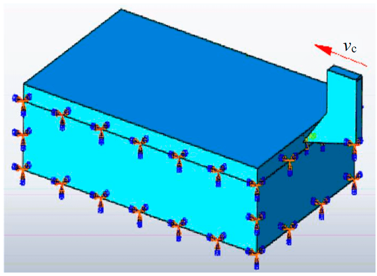
Fig.1. Boundary conditions of the coal mass model
A 3D model of a coal mass 80×50×20 mm with a cut thickness h = 2 mm was built (Fig.1). The cutter is fixed in a vertical position, it is given speed in a horizontal direction parallel to the initial upper surface of the mass. In the models of the cutting process, the cutting speed vc= = 0.08 m/s, the coefficient of friction between the cutter and the mass μ = 0.22 are assumed. Friction coefficients in other friction pairs are taken equal to zero.
Results
When cutting coal, the stress in mass (Fig.2) is distributed in accordance with closed curves around the cutter without kinks: the closer to the cutter, the greater the stress in the mass.
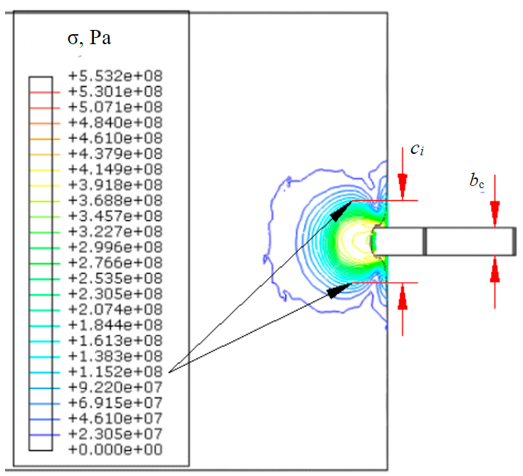
Fig.2. Stress distribution σ when cutting with a single cutter
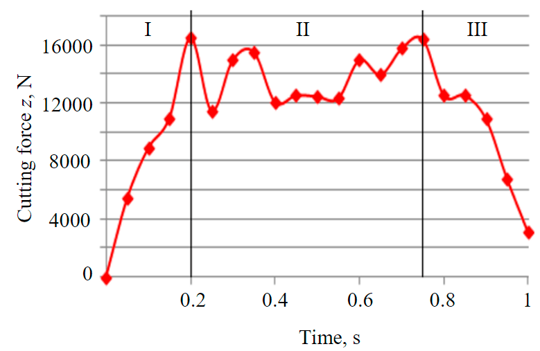
Fig.3. Change in cutting force per single cut
Fig.4. Boundary conditions of the model with paired cutters
From the formula and Fig.2, according to the simulation results, it follows that in the zone сi значение напряжения σi = 11.52 MPa (Fig.2) greater than the value of the main fracture stress of coal σmax = 10 MPa. The stress zone width is greater than the width of the cutting edge of the cutter bс by 2.81 times.
The process of a single cut is represented (Fig.3) by three zones:
- zone I – cutting force steadily increases and bс reaches the maximum value z = 16.5 kN;
- zone II – stationary cutting mode: the cutting force changes from 16.5 to 11.5 kN with
a constant value of the mathematical expectation estimations; - zone III – the force steadily decreases from
z = 16.4 kN to zero.
The change in force in zone II adequately reflects the features of cutting coal with a single cutter and can be used to analyze stationary cutting conditions.
Similar to modeling with a single cutter, modeling of paired slices was carried out, which are installed without leading each other in parallel, close planes of rotation with a step tcp = 1.5bс (Fig.4).
Cutter pitch tcp = 1.5bс. Isolines of equal stresses in the mass when cutting coal with paired cutters (Fig.5, a) are located in the form of closed curves around the cutter: the closer to the cutter, the greater the stress in the rock mass. In zone сi, the stress value σi = 11.52 MPa greater than the value of the main fracture stress of coal σmax = 10 MPa. The width of the stress zone when cutting with paired cutters is greater than the width of the cutting edge of the cutter bс by 2.99 and 1.58 times when cutting with one cutter.
Cutter pitch tcp = 2.0bс. From Fig.5, b it follows the results of coal cutting simulation: in the zone сi, the stress value σi = 11.74 MPa is greater than the value of the main coal fracture stress σmax = 10 MPa.
The width of the stress zone is 4.6 times greater than the width of the cutting edge of the cutter bс and 1.7 times when cutting with one cutter. The distribution lines of equal stresses are continuous seamless curves, but small wrinkles appear. The stresses in these places exceed the maximum yield strength of the material. Looking at the distribution of stresses, the cutters work effectively by supporting each other and have proven to be more efficient than when cutting with cutter pitches tcp = 1.5bс.
Fig.5. Stress distribution σ when cutting with paired cutters: cutter pitch tcp = 1.5 (а); 2.0 (b); 2.5bс (c)
Cutter pitch tcp = 2.5bс. It follows from the results of coal cutting modeling that the stress value σi = 11.53 MPa (Fig.5, c) is greater than the value of the main coal fracture stress σmax = 10 MPa.
At the same time, the width of the stress zone is 2.65 times greater than the width of the cutting edge of the cutter bс and 0.95 times less than when cutting with one cutter. The general curve, reflecting the distribution of stresses in the mass between two cutters, is characterized by the presence of cracks and stresses in these positions, which are less than the critical stress of the material. Thus, when the cutting paired incisors are located with the installation step tcp = 2.5bс, they do not support each other. The size of fragments of destruction particles is much smaller when cutting with paired cutters with a cutting step of 1.5; 2.0bс. In a small stress zone between two cutters, smaller chips are formed, which increases energy consumption and reduces the efficiency of the process.
The length of single and paired cuts practically does not change in the direction of the cutting speed. In the process of a paired cut, the conjugated stress distribution zones with characteristic lines of closed arcs are formed in the mass. In Fig.5, a, b, the stress zones are united by isolines of equal stresses, which creates conditions for the formation of larger chips. Between adjacent conjugated stress zones, regions are formed that cause the appearance of small chips. In the steady cutting mode, different from the reference one (with a constant cut thickness h = 3 mm), the effective cutting forces and specific energy consumption depend not only on the cutting resistance and the degree of fragility of the mass, but also on the cutting conditions. Therefore, the definition of cutting forces is based on the value of the specific cutting energy in the reference mode.
Results discussion
The processes of paired cuts with different steps of setting the incisors have the following zones (Fig.6):
- zone I – cutting force steadily increases and bс reaches the maximum value z = 16.5 kN;
- zone II – stationary cutting mode: the cutting force changes from 16.5 to 11.5 kN with a constant value of the mathematical expectation estimations;
- zone III – the force steadily decreases from z = 16.4 kN to zero.
From Fig.6 it can be seen that the forces during cutting with paired cutters with cutter installation steps tcp = 1.5; 2.0bс less than when cutting with tcp = 2.5bс.
From Figs. 3 and 6 it follows that when cutting with paired cutters with a setting step tcp = 2.0bс, the cutting forces are the smallest, and the width of the chip fragments is the largest. This confirms the presence of rational slices in terms of their effectiveness and the possibility of choosing the values of the parameters of paired slices in comparison with single and group slices.
Fig.6. Cutting forces on cutters 1 – tcp = 1.5; 2 – 2.0; 3 – 2.5bс
Conclusion
Based on the results of coal cutting simulation using ABAQUS software, the following conclusions can be drawn:
- in the process of separating coal from the mass by paired cuts, the yield of large fractions increases compared to a single cut;
- at tcp = 2.0bс, fragments with the largest chipping area are formed;
- when using paired and group cuts, the formation of combined stress zones in the massif is possible, causing an increase in the size of chip fragments by 1.3-1.8 times;
- when cutting coal with paired cutters with tcp = 2.0bс, the cutting forces on a single cutter are less than when cutting with a single cutter or paired cutters with tcp = 1.5; 2.5bс;
- the proposed rational pair and group cuts in terms of shape and cross-sectional area provide the possibility of creating more energy-efficient sequential-group schemes for placing cutters on the auger executive bodies of shearers.
References
- Khoreshok A.A., Mametev L.E., Tsekhin A.M. et al. Mining machines and complexes. Mining machine cutting tool. Kemerovo: Kuzbasskii gosudarstvennyi tekhnicheskii universitet imeni T.F.Gorbacheva, 2018, p. 286 (in Russian).
- Linnik Yu.N., Linnik V.Yu., Petrov I.V., Zich A. Assessment of Reliability of Coal Mining Machine Cutters. Ugol'. 2021. N 2, p. 10-13 (in Russian). DOI: 10.18796/0041-5790-2021-2-10-13
- Khoreshok A.A., Mametev M.E., Tsekhin A.M. et al. Manufacture and operation of destructive tools for mining machines. Tomsk: Izdatelstvo Tomskogo politekhnicheskogo universiteta, 2013, p. 296 (in Russian).
- Zagrivnyi E.A., Basin G.G. External dynamics formation in mining machines. Journal of Mining Institute. 2016. Vol. 217, p. 140-149 (in Russian).
- Meshkov A.A., Kazanin O.I., Sidorenko A.A. Implementation of production potential of high-performance equipment – A key trend of improvement in underground mining of power-generating coal. Mining informational and analytical bulletin. 2020. N 12, p. 156-165 (in Russian). DOI: 10.25018/0236-1493-2020-12-0-156-165
- Zvonarev I.E., Shishlyannikov D.I. Efficiency improvement of loading of potassium ore by means of “Ural-20R” heading-and-winning machine. IOP Conference Series: Earth and Environmental Science. 2017. Vol. 87. Iss. 2. N 022025. DOI: 10.1088/1755-1315/87/2/022025
- Linnik Yu.N., Linnik V.Yu., Voronova E.Yu. et al. Analysis of the Structure of Failures of Augers of Cleaning Combines. Ugol'. 2021. N 4, p. 20-24 (in Russian). DOI: 10.18796/0041-5790-2021-4-20-24
- Kuvshinkin S.Y., Ivanova P.V. Developing a methodology for estimation of excavation techniques for given operating conditions. International Conference on Innovations and Prospects of Development of Mining Machinery and Electrical Engineering, 24-27 April 2019, Saint-Petersburg, Russian Federation. IOP Conference Series: Earth and Environmental Science. 2019. Vol. 378. N 012121. DOI: 10.1088/1755-1315/378/1/012121
- Shibanov D.A., Ivanov S.L., Shishkin P.V. Digital technologies in modeling and design of mining excavators. International Conference on Innovations, Physical Studies and Digitalization in Mining Engineering (IPDME) 2020, 23-24 April 2020, Saint Petersburg, Russian Federation. Journal of Physics: Conference Series. 2021. Vol. 1753. N 012052. DOI: 10.1088/1742-6596/1753/1/012052
- Bolobov V.I., Bochkov V.S. On capabilities of thermomechanical treatment in increasing durability of short service life elements of mining аnd processing equipment. Journal of Mining Institute. 2016. Vol. 221, p. 688-691. DOI: 10.18454/PMI.2016.5.688
- Shishlyannikov D.I., Trifanov M.G., Chekmasov N.V., Ivanov S.L. The Choice of Technically Justified Operating Modes of “Ural” Combines on the Basis of an Estimation of their Drivers Load Under Real Operating Conditions. Mining Equipment and Electromechanics. 2017. N 7, p. 3-8 (in Russian).
- Babyr N.V., Korolev A.I., Neupokoeva T.V. Enhancement of powered cleaning equipment with the view of mining and geological conditions. IOP Conference Series: Earth and Environmental Science. 2018. Vol. 194, N 032004. DOI: 10.1088/1755-1315/194/3/032004
- Zhabin A.B., Polyakov A.V., Averin E.A. et al. Ways of Development for the Theory of Rock and Coal Destruction by Picks. Ugol'. 2019. N 9, p. 24-28 (in Russian). DOI: 10.18796/0041-5790-2019-9-24-28
- Zhabin A.B., Polyakov A.V., Averin E.A., Sarychev V.I. State of Scientific Researches in the Field of Rock Destruction by Picks at the Turn of the Century. Izvestija Tulskogo gosudarstvennogo universiteta. Nauki o zemle. 2018. N 1, p. 230-247 (in Russian).
- Pavlenko M.V., Khaidina M.P., Kuziev D.A. et al. Impacts of the Combine Harvester in the Production of Coal to Increase Methane Recovery Array in the Workspace Lava. Ugol'. 2019. N 4, p. 8-11. DOI: 10.18796/0041-5790-2019-4-8-11
- Nguyen V.S., Nguyen K.L., Lykov Yu.V. Increasing the yield of coarse coal fractions in shearing. Gornyi zhurnal. 2021. N 2, p. 97-100 (in Russian). DOI: 10.17580/gzh.2021.02.13
- Zhabin A.B., Polyakov A.V., Averin E.A. et al. Estimation of abrasiveness impact on the parameters of rock-cutting equipment. Journal of Mining Institute. 2019. Vol. 240, p. 621-627. DOI: 10.31897/PMI.2019.6.621
- Yungmeister D.A., Lavrenko S.A., Yacheikin A.I., Urazbakhtin R.Y. Improving the shield machine cutter head for tunneling under the conditions of the Metrostroy Saint Petersburg mines. ARPN Journal of Engineering and Applied Sciences. 2020. Vol. 15. N 11, p. 1282-1288.
- Jinxia Liu, Chao Ma, Qingliang Zeng, Kuidong Gao. Discrete Element Simulation of Conical Pick’s Coal Cutting Process under Different Cutting Parameters. Hindawi Shock and Vibration. 2018. Vol. 2018. N 7975141. DOI: 10.1155/2018/7975141
- Xiaohui Liu, Songyong Liu, Lie Li, Xinxia Cui. Experiment on Conical Pick Cutting Rock Material Assisted with Front and Rear Water Jet. Hindawi Publishing Corporation Advances in Materials Science and Engineering. 2015. Vol. 2015. N 506579. DOI: 10.1155/2015/506579
- Prokopenko S.A., Sushko A.V., Kurzina I.A. New design of cutters for coal mining machines. VI International Scientific Practical Conference on Innovative Technologies and Economics in Engineering, 21-23 May 2015, Yurga, Russia. IOP Conference Series: Materials Science and Engineering. 2015. Vol. 91. N 012058. DOI: 10.1088/1757-899X/91/1/012058
- Kazanin O.I., Yaroshenko V.V. Decrease in coal losses during mining of contiguous seams in the near-bottom part at Vorkuta deposit. Journal of Mining Institute. 2020. Vol. 244, p. 395-401. DOI: 10.31897/PMI.2020.4.1
- Prokopenko S.A., Filatov Yu.M., Li Hi Un. The Development of Safe and Effective Cutting Tool for Mining Machine. Mining informational and analytical bulletin. 2017. N S5-1, p. 490-499 (in Russian).
- Khoreshok A., Ananiev K., Ermakov A. et al. Determination of the rational number of cutters on the outer cutting drums of geokhod. Acta Montanistica Slovaca. 2020. Vol. 25. Iss. 1, p. 70-80. DOI: 10.46544/AMS.v25i1.7
- Johnson G.R., Cook W.H. Fracture characteristics of three metals subjected to various strains, strain rates, temperatures, and pressures. Engineering Fracture Mechanics. Vol. 21. Iss. 1, p. 31-48.
- Johnson G.R., Cook W.H. A Сonstitutive model and data for metals subjected to large strains. High rates and high temperatures. Proceedings of the 7th Intern symp on ballistics, 19-21 April 1983, The Hague, The Netherlands. Roy Institute of Engineers in the Netherlands, 1983, p. 541-547.
- Beijing Xie, Zheng Yan, Yujing Du et al. Determination of Holmquist–Johnson–Cook Constitutive Parameters of Coal: Laboratory Study and Numerical Simulation. Processes. 2019. Vol. 7. Iss. 6. N 386. DOI: 10.3390/pr7060386
- Dewangan S., Chattopadhyaya S. Characterization of Wear Mechanisms in Distorted Conical Picks After Coal Cutting. Rock Mechanics and Rock Engineering. 2016. Vol. 49, p. 225-242. DOI: 10.1007/s00603-015-0726-x
- Zlotnikov E.G., Khalimonenko A.D., Kazakov D.Yu. Modeling and calculation of load on cutting inserts of disk milling cutters in software environment of Autodesk Inventor. IOP Conference Series: Earth and Environmental Science. 2018. Vol. 194. N 022048. DOI: 10.1088/1755-1315/194/2/022048
- Schwer L. Optional Strain-Rate Forms for the Johnson Cook constitutive model and the Role of the Parameter Epsilon 01. 6th European LS-DYNA Users’ Conference, Gothenburg, Sweden. DYNAlook, 2007, p. 17.
- Voronova E.Y., Khazanovich G.Sh. General methodology for the optimization of the parameters of aggregated tunneling systems. International Conference on Mechanical Engineering, Automation and Control Systems 2018, 12-14 December 2018, Novosibirsk, Russian Federation. IOP Conference Series: Materials Science and Engineering. 2019. Vol. 560. N 012048. DOI: 10.1088/1757-899X/560/1/012048
- Jing Xu, Zhongbin Wang, Chao Tan et al. Cutting Pattern Recognition Method for Shearers Based on Improved Ensemble Empirical Mode Decomposition and a Probabilistic Neural Network. Sensors. 2015. Vol. 15. Iss. 11, p. 27722-27737. DOI: 10.3390/s151127721
- Hongqing Zhu, Shuhao Fang, Yilong Zhang et al. Numerical simulation of the dynamic distribution characteristics of the stress, strain and energy of coal mass under impact loads. Scientific Reports. 2020. Vol. 10. N 16849. DOI: 10.1038/s41598-020-74063-3
- Xuefeng Li, Shibo Wang, Shirong Ge et al. Numerical simulation of rock fragmentation during cutting by conical picks under confining pressure. Comptes Rendus Mécanique. 2017. Vol. 345. Iss. 12, p. 890-902. DOI: 10.1016/j.crme.2017.09.004