
Method for predicting the stress state of the lining of underground structures of quasi-rectangular and arched forms
- 1 — Ph.D., Dr.Sci. Associate Professor Saint Petersburg Mining University
- 2 — Postgraduate Student Saint Petersburg Mining University ▪ Orcid

Abstract
A method for predicting the stress-strain state of the lining of underground structures, the shape of the cross-section of which is different from the circular outline, is considered. The main task of the study is to develop a methodology for assessing the influence of the parameters of the cross-section shape of underground structures on the stress state of the lining. To solve this problem, a method for calculating the stress state of the lining for arched tunnels with a reverse arch and quasi-rectangular forms is substantiated and developed. The methodology was tested, which showed that the accuracy of the prediction of the stress state of the lining is sufficient to perform practical calculations. An algorithm for multivariate analysis of the influence of the cross-sectional shape of underground structures of arched and quasi-rectangular shapes on the stress state of the lining is proposed. Parametric calculations were performed using the developed algorithm and regularities of the formation of the stress state of the lining of underground structures for various engineering and geological conditions, as well as the initial stress state field, were obtained. A quantitative assessment of the influence of geometric parameters of tunnels on their stress-strain state was performed.
None
Introduction
Developments in the design of tunneling complexes allow them to be used for the mechanized construction of tunnels not only circular, but also arched, oval and quasi-rectangular sections. The choice of the cross-section shape is determined by a number of factors, among which the most significant are: the purpose of the underground structure; geotechnical conditions of construction; accepted construction technology; estimated economic costs. Circular cross-section is the most common in the construction of tunnels in weak soils, which is determined by the availability and reliability of equipment for the construction of tunnels of such shapes, as well as the fact that for most mining and geological conditions, this shape is the most stable [1, 2]. The disadvantage of the circular shape is the low cross-section utilization coefficient – it decreases with increasing cross-sectional area. Tunnels of non-circular outlines have a higher cross-section utilization coefficient compared to circular ones. However, such a change in shape leads to an increase in stresses and a decrease in the stability of the tunnel lining. It is possible to reduce the stresses in the lining by optimizing the shape, in particular, changing the radius of the walls and the arch. Taking into account the fact that there are no recommendations for optimizing the geometry of non-circular sections in general, it is necessary to develop a design solution that will increase the efficiency of using non-circular cross-sectional shapes of underground structures.
Research in the field of calculating the stress state of the lining of underground structures is presented in scientific papers aimed at studying the stress-strain state of the lining based on analytical solutions [3-6], numerical modeling [7-9] and experimental studies [10-13]. Large-scale experimental studies of the stress state of prefabricated linings for circular tunnels [14-16], rectangular tunnels [17], quasi-rectangular tunnels [18-20], crescent tunnels [21] and elliptical tunnels [22] have been carried out. Taking into account the complexity of conducting large-scale experimental studies, the results of such works are not generalizing, but are aimed at solving problems in specific mining and geological conditions.
The researchers obtained detailed results of calculating the stress state of the lining of underground structures, performed on the basis of analytical solutions and numerical modeling [23, 24], an approach to parametric analysis of changes in the stress state of the lining of tunnels of rectangular and elliptical [25], circular and rectangular cross-section shapes [26] was proposed. In [27], the influence of the shape of the cross-section of tunnels on the amount of the Earth's surface subsidence is estimated. In the source [28], the influence of twin tunnels of various cross-sectional shapes on the formation of the stress state of the lining was studied. In [29], a number of numerical calculations were performed to assess the effect of the cross-section shape on the stress state of the lining. The results of the performed studies show that the stress state of the lining significantly depends on the shape of the cross section. However, the issues of substantiating the geometric parameters of the lining of non-circular shapes have not been considered in scientific papers.
The main attention is paid to the assessment of the influence of various factors (geological and geometric) on the formation of the stress state of tunnel linings of non-circular shape. The method of calculating the stress state of the lining, based on taking into account the rock mass through hyperstatic reactions (Hyperstatic Reaction Method, HRM), better known as the Metrogiprotrans method, has proven its effectiveness in calculating the lining of circular tunnels [13, 30]. Its application is considered for the calculation of tunnel linings of non-circular cross-sectional shapes: arched with a reverse arch and quasi-rectangular. The main advantage of the HRM method – the speed of calculations – is used to solve the problem of multivariate analysis of the influence of the shape of the tunnel cross-section on the stress state of the lining. An algorithm has been developed to evaluate the effect of the cross-section shape on the stress state of the lining for arched tunnels with a reverse arch and quasi-rectangular cross-section.
The developed method made it possible to identify new patterns of formation of the stress state of the lining of tunnels of various cross-sectional shapes.
Methodology
HRM method for calculating the stress state of the lining of an underground structure
The HRM method belongs to a class of numerical analysis methods in which the stress state of the lining, represented as one-dimensional rod elements, can be determined through integral indicators. The interaction between the lining of the underground structure and the host rock mass is formed through a set of normal and tangential springs, which are connected to the rod elements through adjacent nodes. The mechanical behavior of the rock mass at the pre-limit stage of deformation is assumed on the basis of the linear law of deformation, while the achievement of the limit state is characterized by an ideal plastic flow. Nodal displacements in the HRM method are unknown, their determination allows to establish the values of integral indicators of the stress state of the rod elements, i.e. to determine the stress state of the lining. External pressure in the form of concentrated forces is applied to the nodes. A detailed description of the use of the HRM method for calculating the stress state of the circular shape lining is presented in [13, 30]. In this paper, the HRM method is extended to predict the stress state of non-circular linings (arched shape with a reverse arch, quasi-rectangular shape).
The relation between the global stiffness matrix of the system under consideration K, vectors of unknown displacements U and nodal forces F can be represented as [31]
Expanding equation (1), we obtain:
where ki,a, ki,b, ki,c and ki,d – sub-matrices of the matrix ki; U1, U2, U3, … Un – components of the displacement vector; F1, F2, F3, … Fn – components of the force vector.
The presence of springs along the perimeter of the tunnel affects the stiffness of the considered system of rod elements. This is taken into account by changing the stiffness of each of the rod elements, consequently, the global stiffness matrix.
Methodology for calculating the loads on the lining of tunnels of various shapes
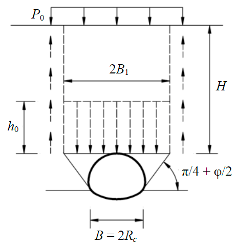
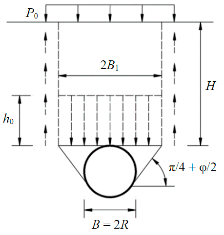
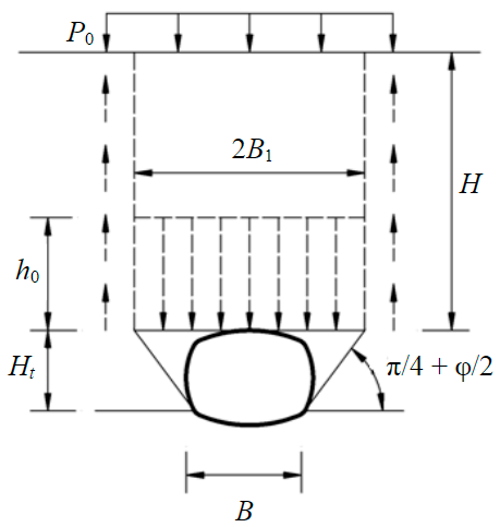
There are various hypotheses of the formation of rock pressure on the lining of underground structures, each of which has its own field of application, based on engineering and geological conditions and depending on the position of the underground structure relative to the Earth's surface. The applicability of methods for calculating loads on the lining has been studied by many scientists and is widely presented in the literature [32-35], therefore it is not the main object of this study. The method of calculating the load on the support proposed by Tertsagi [36] was adopted, which considered the formation of a descending rock pillar with a width of B1, part of the load from which is transferred to the surrounding rock mass due to friction, and the other component is held by the lining of the underground structure, which allows maintaining the equilibrium of the considered system of interaction “underground structure – soil mass”.
According to the methodology proposed by Tertsagi, when the depth of the underground structure is less than two widths, the value of the vertical pressure on the lining of the underground structure is determined by the total weight of the rock pillar:
where γ – average volume weight of overlying rocks; z – the distance from the Earth's surface to the design mark.
For calculated cases when the depth of the underground structure is more than two widths, the calculation of the load on the lining is determined through the value of the effective power of the rocks h0, the weight of the rocks in which determines the amount of pressure:
It is assumed that the descending rock pillar has a width B1, and sliding prisms are formed in the sides of the workings, the slope angle of which is assumed to be equal to (π/4 + φ/2). The value of the effective power of the descending rock pillar is determined by the formula
where B1 – half the width of the descending rock pillar (Table 1); – coupling; K0 – lateral pressure coefficient; H – depth of the underground structure; P0 – additional load applied on the Earth's surface.
Formulas for determining the width B1 of underground structures of various cross-sectional shapes are summarized in Table 1.
Table 1
Determination of the width of the underground structure
|
Tunnel cross-section shape |
The formula for calculating half the width |
Calculation scheme |
|
Circular |
where R – tunnel radius; φ – internal friction angle |
|
|
Quasi-rectangular |
where В – width of the underground structure; |
|
|
Arched with a reverse arch |
where Rc – tunnel half-width |
 |
Features of preparation of the calculation model within the HRM method
When performing calculations of the stress state of the tunnel lining, the load transfer schemes indicated in Fig.1, a-c are adopted. The interaction between the lining of the underground structure described by the rod elements and the rock mass is carried out through springs oriented in the normal and tangential directions relative to the contour of the underground structure (Fig.1, d). The stiffness of normal and tangential springs is defined as kn and ks, respectively. The values of kn and ks are determined through the values ηn and ηs, which characterize the ability of the host rock mass to resist deformation.
The nonlinear dependence determining the relation between the deformation of the lining δ and the reaction of the rock mass p to these deformations is presented in [13, 30]:
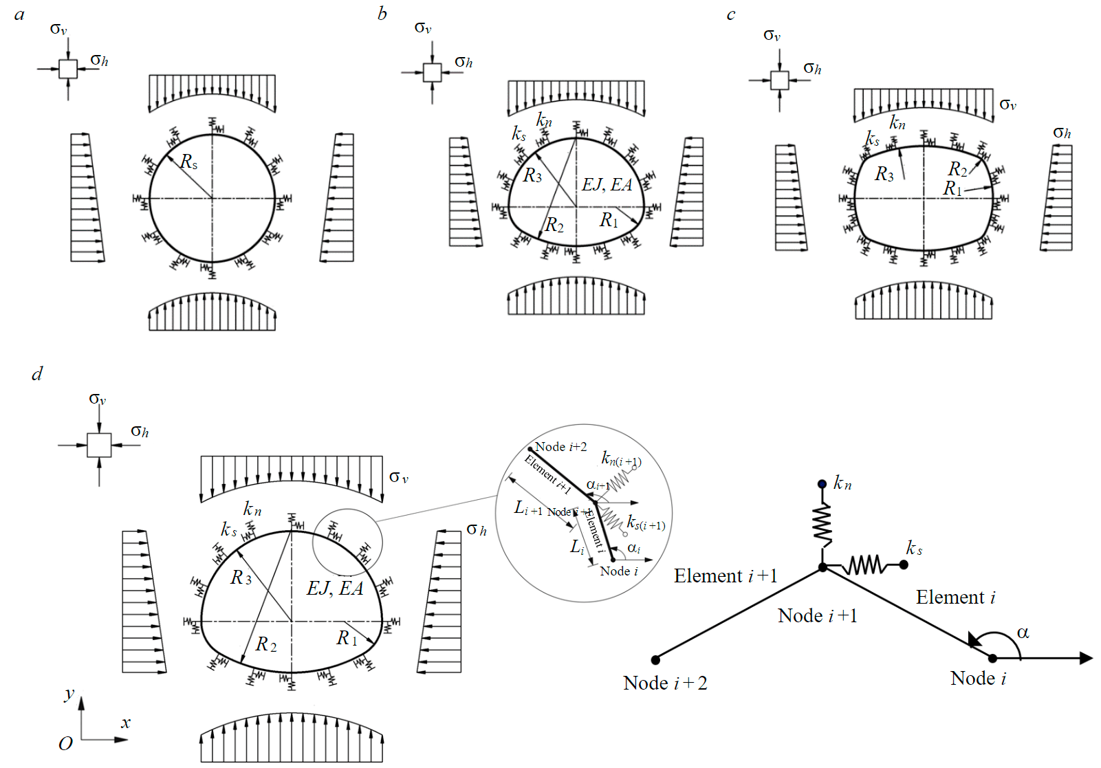
Fig.1. Calculation schemes for the prediction of the stress-strain state of the lining of underground structures of various cross-sectional shapes: a – circular shape; b – arched shape with a reverse arch; c – quasi-rectangular shape; d – scheme of the organization of interaction between the lining of an underground structure and a rock mass σv, σh – vertical and horizontal loads, respectively; EA, EJ – axial and bending stiffness of the lining, respectively; E – the modulus of deformation of the lining material; A – the cross-section area of the lining; J – moment of inertia of the lining; R – radius of the underground structure (circular cross-section shape); R1 – side wall radius; R3 – radius of the arch of an underground structure; R2 – the radius of the reverse arch (arched cross-section with a reverse arch) or the supporting part of the arch (quasi-rectangular shape)
where plim – the limit value of the rock mass reaction; η0 – the initial value of the rock mass stiffness at a value of δ close to zero.
The indicator of the relative rock mass stiffness can be expressed as follows:
The stiffness of the springs in the normal direction varies depending on the radius of the underground structure and is determined by the formula
while the stiffness of the springs in the tangential direction can be assumed to be equal to one-third of the stiffness of the springs in the normal direction [13]:
where Es– modulus of the rock mass deformation; vs – coefficient of lateral deformation of the rock mass; Ri – the radius of curvature of the lining at each considered point of its perimeter.
The limiting values of the reaction of the rock mass in the radial pn,lim and tangential ps,lim directions depend on the strength characteristics of the rocks (coupling and internal friction angle) of the magnitude characterizing the comprehensive compression of the rocks Δσconf :
The stiffness of the springs kn,1 and ks,1 can be determined by the following formulas:
where Li –1 – distance between nodes i and i – 1; Li – distance between nodes i and i + 1.
When performing calculations, it was noted that the formation of the stress state of the lining of an underground structure is significantly influenced by its weight. Thus, in [37] it was shown that pressure reduction in the lower part of the underground structure allows for better convergence with the forecast results based on numerical modeling. When performing calculations, it is assumed that the value of the active pressure is reduced in relation to its maximum value by 10 % [38].
An algorithm for determining the shape of the cross-section of an underground structure by the force factor
The algorithm of multivariate analysis of the influence of the cross-section shape of a quasi-rectangular tunnel (Fig.2) on the stress state of the lining consists in splitting the tunnel section into separate segments, the parameters (the position of the center of the segment and the radius) of which are controlled through reference points. First of all, the cross-sectional area of the tunnel is determined in accordance with the size of the approach of buildings for a double-track subway tunnel [39, 40]. The contour of the section in the light of the tunnel of a quasi-rectangular shape should overlap this zone. Taking into account this requirement, a number of mathematical dependencies are proposed to determine the geometric parameters of the quasi-rectangular shape of the tunnel section from the point of view of internal forces arising in the lining of the tunnel.
The following sequence of determining the geometric parameters of a quasi-rectangular tunnel is adopted (Fig.3).
At the initial stage, the geometric center O2 is selected and the radius R2 is calculated. The center O2 (x2, y2) of arc 2 is located on the bisector of the line segment A1A2, which is described by the linear equation y = x + (h1 – d1).
The radius is determined by the formula
where (d2, h1) ‒ coordinates of the point A2.
Fig.2. General algorithm for calculating geometric parameters of the cross-section (a) and various cross-section configurations (b) for non-circular tunnels xA1, xA2 – the horizontal coordinates of points А1 and А2 respectively; х2gh – limit horizontal coordinate of a point O2; R1, R2, R3 – radii of the side wall, the supporting part of the arch and the arch; a11, a22 ‒ the upper limit angle and the lower limit angle of the angles a1 and a2 respectively; Mi ‒ the minimum value of the maximum bending moment at the position of point O2 corresponding to case i (when changing the position of points O1 and O3)
Fig.3. Schematic diagram of the calculation of the geometric parameters of a tunnel of quasi-rectangular cross-section (Arch1, Arch2, Arch3 – the perimeters of the arc of the side wall, the supporting part of the arch and the arch, respectively)
The location of the centers O1, O3 is determined. Arc 2 is bounded by the points A'1 and A'2, located on a circle with the center O2 and radius R2. The angles between the straight line O2A'1, O2A'2 and the horizontal axis must satisfy the condition: α1 = (0, α11) и α2 = (α22, 90).
The center O1 of arc 1 is the intersection of a line passing through point O2 and having a slope tg(α1), and the horizontal x axis: O1(х1,0), x1=-y2/tg(α1)+x2. The center О3 of arc 3 is the intersection of a line passing through point O2 and having a slope tg(α2), and the vertical x axis: O3(0, y3), y3=tg(α2)(-x2)+y2. From here we can express the values of the radii R1 and R3 (m):
where ( xA1',yA1' ) and ( xA2',yA2' ) ‒ the coordinates of the point A'1 and A'2 , respectively.
Adaptation of the HRM method for a tunnel of non-circular cross-section shape was performed in the MatLab software package. The algorithm for calculating the parameters of the tunnel cross-section is also an element of the general program code for calculating the stress state of the lining. The output data are integral indicators of the stress state of the lining (shearing force, bending moment, axial force) and the position of the nodal points of the system after optimization.
A similar algorithm for assessing the influence of the cross-section shape of tunnels on the stress state of the lining has also been developed for tunnels of arched cross-section with a reverse arch (see Fig.1, b), but it is not considered in this paper.
Discussion of the results
Assessment of the reliability of the stress state prediction of the lining in the framework of the HRM method
The formation of the stress state of the lining of underground structures of circular, quasi-rectangular and arched cross-section forms, the parameters of which are shown in Fig.1 and in Table 2, is considered. The calculation of the stress state of the lining is carried out on the basis of the above methodology. The results obtained by the HRM method were compared with the results obtained on the basis of numerical simulation of the interaction of the lining with the rock mass by the finite element method. A detailed statement of the problem within the framework of the finite element method is presented in [38]. When performing calculations, the thickness of the lining was assumed to be equal to 0.5 m. The problem was solved in a plane-deformation formulation, the influence of the face zone on the formation of the load on the lining was not taken into account. The depth of the tunnel (from the ground surface to the crown of the arch of the underground structure) is 10 m, the lateral pressure coefficient for all design cases is 0.6.
Table 2
Geometric parameters of tunnel cross-sections of various shapes
|
Cross-section shape |
R, m |
R1, m |
R2, m |
R3, m |
Cross-section area, m2 |
|
Circular |
4.89 |
– |
– |
– |
75.12 |
|
Quasi-rectangular |
– |
5.35 |
1.00 |
9.95 |
59.78 |
|
Arched with a reverse arch |
– |
2.45 |
8.11 |
5.24 |
69.65 |
The rock mass was considered as a nonlinear deformable medium with a limit on the magnitude of maximum tangential stresses. Physical and mechanical characteristics of the rock mass, showing the mechanical behavior of rocks in the area under consideration, and the lining material:
γ – 18/25 kN/m3; Е – 3.6/35000 MPa; v – 0.495/0.15; с – 25.6/– kPa; φ – 16.5°/– respectively.
The results of the calculation of the stress state of the lining by the HRM method and its comparison with the results obtained based on the solution of the problem by the finite element method are presented in the form of diagrams of bending moments and axial forces along the perimeter of the tunnel lining (Fig.4). The results show good convergence between different schemes of interaction of the rock mass and the lining of the underground structure. The greatest difference in the results between the two methods in terms of the bending moment is observed when considering a tunnel of circular cross-section and is 8.3 %, while for tunnels of quasi-rectangular and arched cross-sections the difference is 1.2 and 2.0 %, respectively. In terms of the magnitude of the axial forces, the difference between the two methods is 5.8, 5.4 and 6.0 %, respectively. From a qualitative point of view, there is a good convergence. The calculations performed with other parameters of the rock mass, support and stress state [38] also show good convergence of the two calculation methods.
Fig.4. Stress state in the lining: а – bending moment; b – axial force 1 – circular (HRM); 2 – arched shape (HRM); 3 – quasi-rectangular (HRM); 4 – circular (Plaxis); 5 – arched shape (Plaxis); 6 – quasi-rectangular (Plaxis)
It can be concluded that the presented method makes it possible to estimate the stress state of the lining with sufficient accuracy for practical calculations. Taking into account the fact that the speed of calculations within the HRM method is several orders of magnitude higher compared to numerical modeling methods, it can be effectively used to solve optimization problems, where the number of computational iterations can range from several hundred to tens of thousands.
The results of the evaluation of the influence of a curved tunnel cross-section on the stress state of the lining
Let's consider an example of the practical implementation of the proposed algorithm for assessing the influence of the tunnel cross-section shape on the stress state of the lining. Engineering and geological conditions for the construction of a quasi-rectangular cross-section tunnel were adopted for Hanoi, Vietnam. The size of the approach of the tunnel structures for the conditions under consideration is shown in Fig.5. The depth of the tunnel is 10 m, the thickness of the lining is 0.5 m. The geometric parameters of the cross-section are calculated according to the algorithm described earlier.
To reduce the calculation time, each calculation case is estimated using a step of 1° for angles α1 and α2 from bounded angles α11 and α22 respectively; 0.1 m to change the parameter x2. When calculating the geometric parameters of the tunnel cross-section, 12479 calculations of the stress state of the lining of the quasi-rectangular cross-section were performed, the estimated time for each case was about two seconds.
The dependence of internal forces and radial displacements of the lining on the radius of the reverse arch R3 of the tunnel is shown in Fig.6. The influence of the radius R3 on the value of the maximum bending moment in the cross section of the lining is significant. An increase in the radius R3 leads to an increase in the maximum bending moment in the lining. The maximum normal force changes slightly when the radius R3 changes.
Also, an increase in the radius R3 leads to the fact that the arch and the reverse arch of the tunnel become flatter. Then the normal vertical load acting on these segments of the lining increases, and the vertical lateral load decreases. The vertical load transmitted to the side wall of the tunnel is also reduced. Thus, the flatter the arch and the reverse arch of the tunnel, the higher the maximum bending moment in the lining of the tunnel. The maximum normal displacement of the tunnel lining increases with increasing radius R3.
Processing of the calculation results allowed to establish that the ratio between the radius R3 and the maximum bending moment in the lining of the tunnel of a quasi-rectangular cross-section shape can be described by the equation
Fig.5. Construction of the clearance diagrams of tunnel structures: a – double-track railway tunnel according to Vietnam standards; b – simplified approach dimension of tunnel structures W0 = 8.88 m; H0 = 5.50 m; s1 = 0.76 m; d1 = 3.68 m; d2 = 4.44 m; h1 = 2.75 m; h2 = 1.54 m; h1 = H0/2 = h2 + s1
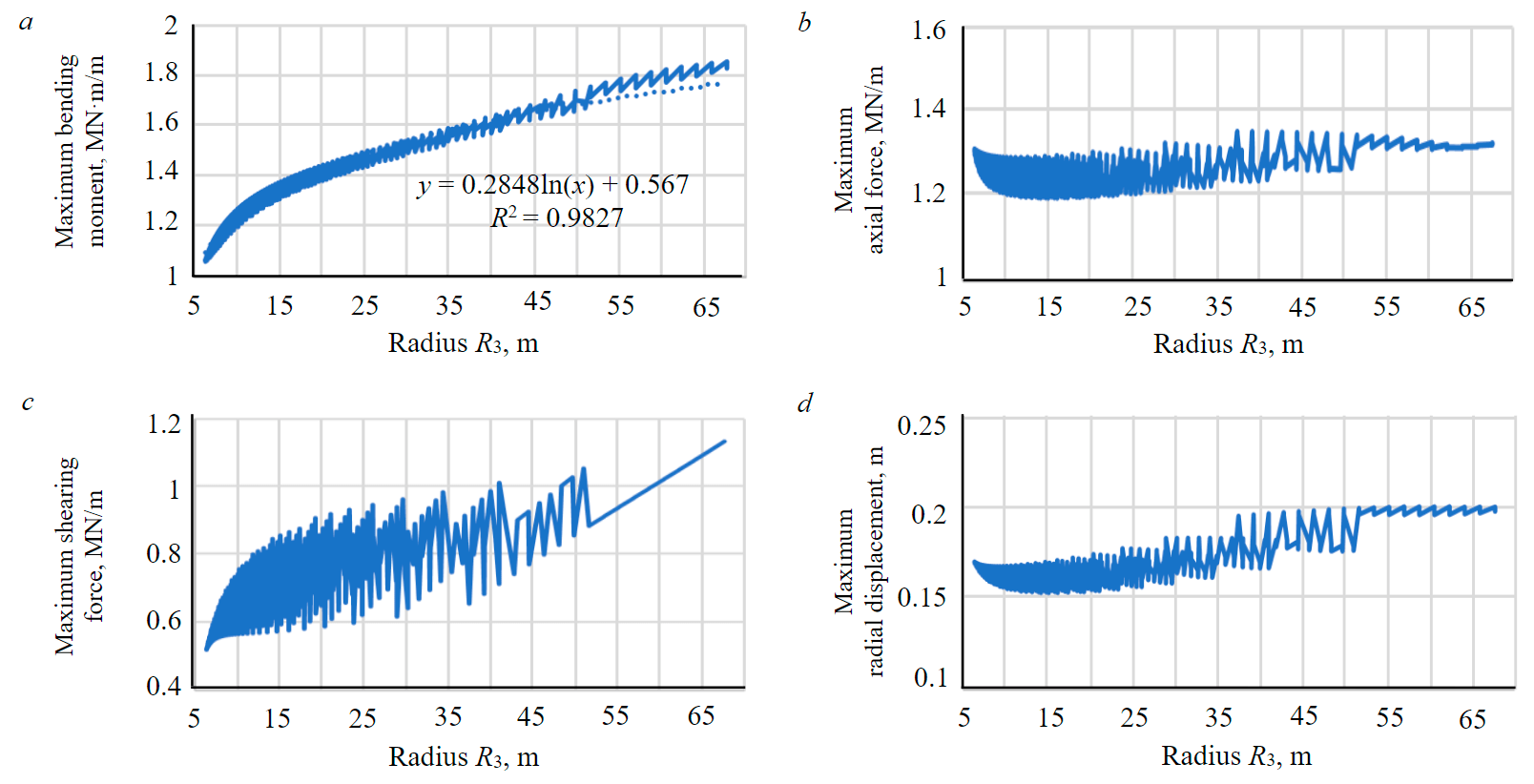
Fig.6. Internal forces and normal displacements arising in the lining of tunnels: a – maximum bending moment; b – maximum axial force; c – maximum shearing force; d – maximum radial displacement
The relation between the maximum bending moment in the tunnel lining and the radii R2, R3, R1 with sufficient accuracy for practical calculations can be described by the equation
It can be seen from equations (14) and (15) that the maximum bending moment in the lining is mainly affected by the radius of the reverse arch and slightly by the radius of the side wall of the tunnel.
A detailed analysis of the calculation results allowed to establish that the value of the maximum bending moment in the section of the tunnel lining for the conditions under consideration varies from 1.05 (the best shape of the cross-section according to the force factor) to 1.85 MN·m/m (the worst shape), i.e. the difference in the values of the bending moment is 75 %. At the same time, the difference in area between the best and worst forms of cross-section was 21 %. It can be concluded that the analysis of the data obtained on the basis of a multivariate calculation allowed to significantly reduce the stress state of the lining while maintaining the minimum size of the cross-section area of the tunnel.
To assess the influence of various parameters and geometry of the tunnel on the stress state of the lining, a multivariate calculation was performed. In a certain range, the modulus of deformation of the rock mass, the depth of the tunnel and the lateral pressure coefficient changed. The modulus of soil deformation is one of the main parameters determining the stress state of the tunnel lining. Its value during the calculations varied from 5 to 200 MPa, while the remaining physical and mechanical characteristics of the rocks remained the same. A total of 26031 calculations were performed. The results are presented in the form of dependences of the change in the maximum value of the bending moment and the axial force in the lining of the tunnel (Fig.7, a). As can be seen from the presented dependencies, the following relation is true for all values of the deformation modules of the rock mass: the higher the value of R3, the higher the absolute value of the bending moment; at the same time, the magnitude of the axial force varies slightly. The obtained results correlate well with the data presented in [41].
With a change in R3 from 10 to 15 m, a sharp increase in the bending moment values is observed, while the values of the maximum normal forces decrease rapidly. A further increase in the R3 index does not have a serious effect on the stressed state of the lining.
The obtained results can be generalized in the form of a dependence that characterizes the relation between the maximum value of the bending moment, geometric parameters and the modulus of deformation of the rock mass:
The assessment of the influence of the initial stress state of the rock mass, expressed in terms of the value of the lateral pressure coefficient K0 and the depth of the tunnel, is presented in the form of plots of changes in the integral indicators of the stress state of the lining (Fig.7, b). The value of the lateral pressure coefficient K0 varied from 0.4 to 1.0. The number of calculations performed was 22778. Based on the analysis of the calculation results, it can be concluded that an increase in K0 leads to a decrease in the maximum value of the bending moment, but the value of the axial force as a whole increases. This tendency is typical for any values of R3. When R3 reaches a value of 10 m, the influence of the coefficient K0 on the stress state of the lining increases. With an increase in the value of R3, the compression effect decreases, therefore, the influence of the R3 indicator on the stressed state of the lining also decreases. According to the results of calculations, a dependence is obtained for determining the maximum value of the bending moment through the value R3 and the lateral pressure coefficient K0:
The lateral pressure coefficient K0 also influences the formation of normal forces in the lining section, however, the degree of this influence is significantly lower than the influence on the bending moment. This result was obtained at different values of R3.
To assess the effect of the radius R3 on the stress state of the lining at different depths of the laying tunnel, additional calculations were performed in the amount of 19524 (Fig.7, с). The depth of laying H varied from 5 to 50 m. Based on the performed studies, it was found that the influence of the parameter R3 on the bending moment decreases as the depth of the tunnel increases.
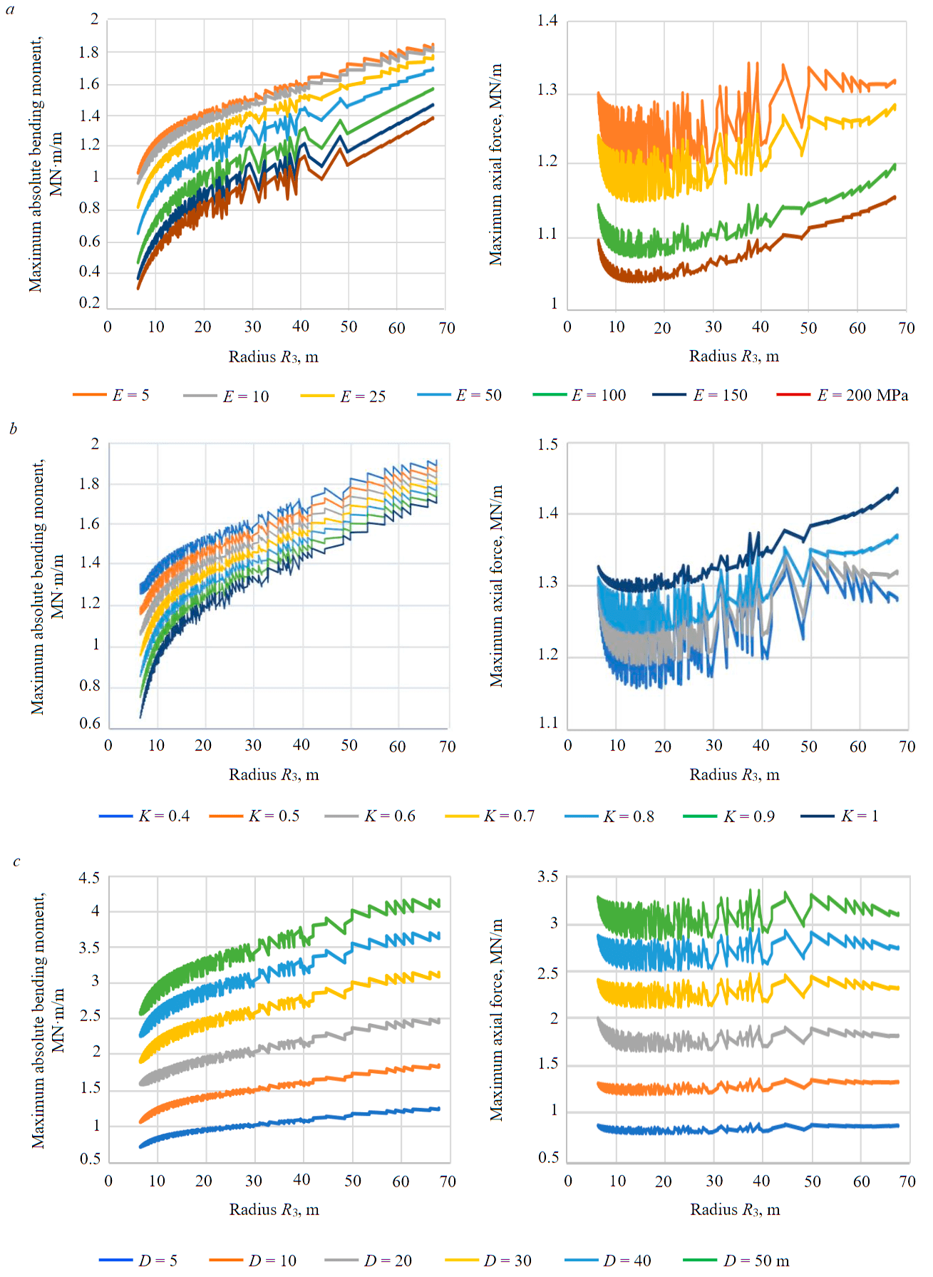
Fig.7. Influence of parameter R3 on the stress state of the tunnel lining depending on the modulus of soil deformation (a), the value of the lateral pressure coefficient (b) and the depth of the tunnel(c)
This can be explained by the fact that with increasing depth, the active loads on the lining also increase, which leads to an increase in the values of the integral indicators of the stress state of the lining. An increase in the R3 indicator leads to the fact that the reverse arch becomes flatter, and the ratio between normal and tangential loads increases, which reduces the vertical load in the tunnel walls. To calculate the value of the maximum bending moment in the lining, depending on the depth of the tunnel and the geometric parameters of the tunnel, the formula is used
Below is a formula that takes into account the influence of a combination of the factors considered: soil deformation modulus Es, tunnel depth H, soil pressure coefficient on the maximum bending moment in the lining. The equation is obtained based on the analysis of 956675 cases:
As can be seen from the presented results, the proposed algorithm makes it possible to effectively assess the influence of the controlling parameters of the tunnel section on the stress state of the lining of various cross-section shapes. At the same time, an automated method for optimizing the shape of the tunnel according to the specified criteria (material strength, structural stability, cross-section area, etc.) has not been proposed, but will be studied in further studies.
Conclusion
As the practice of construction of underground structures shows, their cross-section shapes can be circular, arched with a reverse arch, quasi-rectangular, etc. The HRM method can be used to calculate the stress state of the lining of non-circular shapes, which allows solving the problem with sufficient accuracy for practical calculations. Taking into account the fact that the calculation speed is several orders of magnitude higher than in the finite element method, where the rock mass is considered as a continuous medium described by the corresponding model of its deformation, the HRM method can be used to solve optimization problems – finding the optimal shape of the cross-section of an underground structure under given mining and geological conditions.
Based on the studies performed:
- the HRM method has been developed for calculating underground structures of non-circular cross-section shape taking into account the nonlinear behavior of the rock mass;
- an algorithm for the multivariate calculation of the stress state of the lining of tunnels of arched and quasi-rectangular cross-section forms has been developed;
- the proposed method has been tested for various tunnel construction conditions, and good convergence with the results of numerical modeling obtained in the PLAXIS 2D software package has been obtained;
- a set of parametric calculations has been performed and dependences have been obtained linking the integral parameters of the stress state of the lining (bending moment and axial forces) with the modulus of deformation of the rock, the stress state of the rock mass and the geometric parameters of the cross-section of tunnels of quasi-rectangular and arched shapes;
- analytical expressions are obtained for calculating the maximum values of bending moments in the lining cross-section;
- the direction of further research on the development of an algorithm for finding the optimal shape of the cross-section of tunnels according to the specified criteria is indicated.
References
- Tatiya R. Civil excavations and tunnelling: a practical guide. London: Thomas Telford, 2005, p. 322.
- Yingyongrattanakul N., Adachi T., Tateyama K., Kurahashi M. Optimal shape of underground structure. Modern Tunneling Science and Technology. London: Taylor & Francis, 2001, p. 628.
- Gospodarikov A.P., Vykhodtsev Y.N., Zatsepin M.A. Mathematical modeling of seismic explosion waves impact on rock mass with a working. Journal of Mining Institute. 2017. Vol. 226, p. 405-411. DOI: 10.25515/PMI.2017
- Sammal A.S., Fotieva N.N., Bulychev N.S., Khrenov S.I. Calculation of tunnel linings of variable thickness taking into account the influence of the Earth's surface. Journal of Mining Institute. 2004. Vol. 156, p. 24-26 (in Russian).
- Protosenya A.G., Lebedev M.O. Calculation of the Loads on Linings of Subway Tunnels Constructed in Physically Nonlinear Soil Masses. Journal of Mining Science. 2002. Vol. 38. Iss. 5, p. 418-424. DOI: 10.1023/A:1023975313128
- Protosenya A.G., Karasev M.A., Belyakov N.A. Elastoplastic problem for noncircular openings under Coulomb’s criterion. Journal of Mining Science. 2016. Vol. 1, p. 53-61. DOI: 10.1134/S1062739116010125
- Belyakov N.A., Smirnova O.M., Alekseev A.V., Tan H. Numerical Simulation of the Mechanical Behavior of Fiber-Reinforced Cement Composites Subjected Dynamic Loading. Applied Sciences. 2021. Vol. 11. Iss. 3. N 1112. DOI: 10.3390/app11031112
- Nguyen C.T., Gospodarikov A.P. Hyperstatic reaction method for calculations of tunnels with horseshoe-shaped cross-section under the impact of earthquakes. Earthquake Engineering and Engineering Vibration. 2020. Vol. 19, p. 179-188. DOI: 10.1007/s11803-020-0555-0
- Fan Wang, Biancai Gou, Yawei Qin et al. Modeling tunneling-induced ground surface settlement development using a wavelet smooth relevance vector machine. Computers and Geotechnics. 2013. Vol. 54, p. 125-132. DOI: 10.1016/j.compgeo.2013.07.004
- Bezrodnyi K.P., Lebedev M.O. About rock pressure loads on tunnel linings constructed using trenchless method. Journal of Mining Institute. 2017. Vol. 228, p. 649-653. DOI: 10.25515/PMI.2017.6.649
- Arnau O., Molins C. Experimental and analytical study of the structural response of segmental tunnel linings based on an in-situ loading test. Part 1: Test configuration and execution. Tunnelling and Underground Space Technology. 2011. Vol. 26. Iss. 6, p. 764-777. DOI: 10.1016/j.tust.2011.05.002
- Petrakov D.G., Penkov G.M., Zolotukhin A.B. Experimental study of the effect of rock pressure on sandstone, permeability. Journal of Mining Institute. 2022. Vol. 254, p. 244-251. DOI: 10.31897/PMI.2022.24
- Do N.A., Dias D., Oreste P., Maigre I.D. The behaviour of the segmental tunnel lining studied by the hyperstatic reaction method. European Journal of Environmental and Civil Engineering. 2014. Vol. 18. Iss. 4, p. 489-510. DOI: 10.1080/19648189.2013.872583
- Blom C.B. Design philosophy of concrete linings for tunnel in soft soils. Delft, Netherlands: Delft University, 2002.
- Xiaojun Li, Zhiguo Yan, Zhen Wang et al. Experimental and analytical study on longitudinal joint opening of concrete segmental lining. Tunnelling and Underground Space Technology. 2015. Vol. 46, p. 52-63. DOI: 10. 1016/j.tust.2014.11.002
- Liang Lu, Xilin Lu, Peifang Fan. Full-Ring Experimental Study of the Lining Structure of Shanghai Changjiang Tunnel. Journal of Civil Engineering and Architecture. 2011. Vol. 5. Iss. 8, p. 732-739. DOI: 10.17265/1934-7359/2011.08.007
- Nakamura H., Kubota T., Furukawa M., Nakao T. Unified construction of running track tunnel and crossover tunnel for Unified construction of running track tunnel and crossover tunnel for. Tunnelling and Underground Space Technology. 2003. Vol. 18, p. 253-262. DOI: 10.1016/S0886-7798(03)00034-8
- Xin Huang, Yeting Zhu, Zixin Zhang et al. Mechanical behaviour of segmental lining of a sub-rectangular shield tunnel under self-weight. Tunnelling and Underground Space Technology. 2018. Vol. 74, p. 131-144. DOI: 10.1016/j.tust.2018.01.016
- Xian Liu, Zhen Liu, Yuhang Ye et al. Mechanical behavior of quasi-rectangular segmental tunnel linings: Further insights from full-scale ring tests. Tunnelling and Underground Space Technology. 2018. Vol. 79, p. 304-318. DOI: 10.1016/j.tust.2018.05.016
- Xian Liu, Yuhang Ye, Zhen Liu, Dezhong Huang. Mechanical behavior of Quasi-rectangular segmental tunnel linings: First results from full-scale ring tests. Tunnelling and Underground Space Technology. 2018. Vol. 71, p. 440-453. DOI: 10.1016/j.tust.2017.09.019
- Trushko V.L., Protosenya A.G., Trushko O.V. Stress-strain behavior of the workings during the rich iron ores development under the confined aquifers. International Journal of Applied Engineering Research. 2016. Vol. 11. Iss. 23, p. 11153-11164.
- Feng Yang, Xinlei Sun, Jiahong Zou, Xiangcou Zheng. Analysis of an elliptical tunnel affected by surcharge loading. Proceedings of the Institution of Civil Engineers – Geotechnical Engineering. 2019. Vol. 172. Iss. 4, p. 312-319. DOI: 10.1680/jgeen.16.00122
- Palassi M., Mohebbi M. Design of Lining of Tunnels Excavated in Soil and Soft Rock. The Electronic Journal of Geotechnical Engineering. 2008. Vol. 3, p. 1-15.
- Protosenya A., Vilner M. Assessment of excavation intersections’ stability in jointed rock masses using the discontinuum approach. Rudarsko-geološko-naftni zbornik. 2022. Vol. 38 (2), p. 137-147. DOI: 10.17794/rgn.2022.2.12
- Wang H., Zeng G., Jiang M. Analytical stress and displacement around non-circular tunnels in semi-infinite ground. Applied Mathematical Modelling. 2018. Vol. 63, p. 303-328. DOI: 10.1016/j.apm.2018.06.043
- Abdellah W.R., Ali M.A., Yang H.S. Studying the effect of some parameters on the stability of shallow tunnels. Journal of Sustainable Mining. 2018. Vol. 17. Iss. 1. P. 20-33. DOI: 10.1016/j.jsm.2018.02.001
- Rostami A., Asghari N., Ziarati M.A. et al. Investigating Effect of Tunnel Gate Investigating Effect of Tunnel Gate Inserted Forces on Its Coverage and Soil Surface Settlement. Journal of Civil Engineering. 2016. Vol. 6. Iss. 3. p. 358-369. DOI: 10.4236/ojce.2016.63030
- Vinod M., Khabbaz H. Comparison of rectangular and circular bored twin tunnels in weak ground. Underground Space. 2019. Vol. 4. Iss. 4, p. 328-339. DOI: 10.1016/j.undsp.2019.03.004
- Do N.A., Dias D., Zhang Z. et al. Study on the behavior of squared and sub-rectangular tunnels using the Hyperstatic Reaction Method. Transportation Geotechnics. 2020. Vol. 22. N 100321. DOI: 10.1016/j.trgeo.2020.100321
- Oreste P. A numerical approach to the hyperstatic reaction method for the dimensioning of tunnel supports. Tunnelling and Underground Space Technology. 2007. Vol. 22. Iss. 2, p. 185-205. DOI: 10.1016/j.tust.2006.05.002
- Huebner K.H., Dewhirst D.L., Smith D.E., Byrom T.G. The finite element method for engineers. New York: John Wiley and Sons, 2001, p. 744.
- Baklashov I.V., Kartoziya B.A. Mechanics of underground structures and the construction of supports. Moscow: Student, 2012, p. 543 (in Russian).
- Bulychev N.S. Mechanics of underground structures. Moscow: Nedra, 1994, p. 382 (in Russian).
- Kolymbas D. Tunnelling and Tunnel Mechanics. A rational Approach to Tunneling. Berlin: Springer, 2005, p. 439.
- Széchy K. The Art of Tunnelling. Budapest: Akadémiai Kiadó, 1973, p. 1097.
- Takano Y.H. Guidelines for the design of shield tunnel lining. Tunneling and Underground Space Technology. 2000. Vol. 15. Iss. 3, p. 303-331. DOI: 10.1016/S0886-7798(00)00058-4
- Do N.A., Dias D. Tunnel lining design in multi-layered grounds. Tunnelling and Underground Space Technology. 2018. Vol. 81, p. 103-111. DOI: 10.1016/j.tust.2018.07.005
- Nguyen T.T., Do N.A., Karasev M.A. et al. Influence of tunnel shape on tunnel lining behavior. Proceedings of the Institution of Civil Engineers – Geotechnical Engineering. 2021. Vol. 174. Iss. 4, p. 355-371. DOI: 10.1680/jgeen.20.00057
- Nguyen Tai Tien, Karasev M.A. Optimization of Geometry Design of Quasi-Rectangular Section Tunnel by the Force Criterion. Mining Informational and Analytical Bulletin. 2021. Vol. 6, p. 59-71 (in Russian). DOI: 10.25018/0236_1493_2021_6_0_59
- Du D., Dias D., Do N. Lining performance optimization of sub-rectangular tunnels using the Hyperstatic Reaction Method. Computers and Geotechnics. 2020. Vol. 117. N 103279. DOI: 10.1016/j.compgeo.2019.103279
- Gospodarikov P., Zatsepin M. Mathematical modeling of boundary problems in geomechanics. Gornyi zhurnal. 2019. Vol. 12, p. 16-20 (in Russian). DOI: 10.17580/gzh.2019.12.03