
Numerical modeling of a double-walled spherical reservoir
- 1 — Ph.D., Dr.Sci. Professor Ufa State Petroleum Technological University
- 2 — Engineer CJSC “Neftemontazhdiagnostika”

Abstract
Extensive and important class of multilayer shell structures is three-layer structures. In a three-layer structure, a rigid filler plays an important role, due to which the bearing layers are spaced that gives the layer stack high rigidity and durability with a relatively low weight. By combining the thicknesses of the bearing layers and the filler, the desired properties of a three-layer shell structure can be achieved. Compared with traditional single-walled, three-layer construction has increased rigidity and durability, which allows reducing the thickness and weight of the shells. In order to reduce the metal content of the spherical reservoir for storing liquefied gases, this work considers the design of a double-walled reservoir, in which the inter-wall space is filled with reinforced polyurethane. Numerical modeling made it possible to determine the parameters of the stress-strain state of the structure with an error of no more than 5 %. It has been established on the example of a reservoir with a volume of 4000 m3 that the spatial structure of the spherical reservoir wall can reduce the metal content up to 19 %. Field of application for the research results is the assessment of the stress-strain state of spherical reservoirs at their designing. Method for building the structure of a double-walled spherical reservoir in the SCAD software has been developed, which allows calculating the stress-strain state (SSS) by the finite element method. Numerical model of a double-walled spherical reservoir has been developed. It was found that to obtain calculation results with an error of P ≤ 5 % the size of the final element should not exceed 300×300×δ mm. Design of a double-walled spherical reservoir was investigated. Design parameters have been established to ensure the operational reliability of the structure with a decrease in metal content in comparison with a single-wall reservoir by 19 %.
None
Introduction. Main approaches to the study of orthotropic shells were considered by V.Z.Vlasov [12]. In work [4] A.I.Golovanov and co-authors considered the problems of constructing models of three-layer shells by the finite element method (FEM). They developed a quadratic finite element, which extends to the class of physically and geometrically non-linear problems. Method of stepwise loading is used in the form of a modified Lagrange setting.
In the work [9] R.Z.Kiseleva proposed an algorithm for the formation of stiffness matrices of volumetric finite elements (FE) with nodal unknown values in the form of displacements and their first derivatives. She also proposed an algorithm for transforming the stiffness matrices and vectors of nodal loads of FE, adjacent to the interface between the layers of revolution shells with different physical and mechanical properties.
Number of works investigating three-layer structures increases annually. However, most of them are devoted to the consideration of plates for a rectilinear plane. Many scientific publications are devoted to multilayer shells for flat coatings with different characteristics of layer rigidity [5, 15].
Differential theories are the most widespread in practical calculations: the theory of elastoplastic processes by A.A.Ilyushin and the theory of plastic flow with combined hardening, based on the concept of microstresses by V.V.Novozhilov.
Currently, there are many options for models of elastoplastic deformation of a metal based on the theory of flow during its hardening. Metal is assumed homogeneous and initially isotropic. In the process of elastoplastic deformation, only deforming anisotropy can arise in it. Review of works based on flow theory is presented in [1]. Work [11] was carried out under the scientific supervision of Academician of the Russian Academy of Natural Sciences V.S.Bondar, in which a variant of the mathematical model of inelastic deformation and accumulation of damage to construction materials is presented. Software package for assessing and predicting the resource of construction materials has been developed, which consists of a module for determining material functions based on the results of a basic experiment and a module for calculating the kinetics of the stress-strain state and the process of damage accumulation. An applied version of the elastoplastic processes theory and the accumulation of damage to materials, based on the theory of V.S.Bondar, is proposed in [14]. The author tested a version of the theory on a number of construction materials and pointed out that the error in the calculation results does not exceed 10 % of the experimental results. However, this theory can be applied only at small deformations. In the theory of shells, small deformations are understood as deformations that do not exceed the wall thickness.
T.R.Ishchanov [8] analyzed the stress-strain state of thin shells taking into account the transverse shear for different variants of approximation for angular displacements. On the basis of V.V.Novozhilov's relations, an algorithm for studying SSS using scalar and vector interpolation procedures has been developed. Review of works devoted to the study of methods for reducing a three-dimensional problem of elasticity theory to a two-dimensional theory of plates and shells is given in [3] N.A.Gureeva [6] performed a comparative analysis for the efficiency of using finite elements of triangular and quadrangular forms of calculating the revolution shells. It is shown that the calculations performed with the use of triangular FE have a significantly greater error in comparison with the finite element solutions obtained using the quadrangular FE.Work [10] is devoted to the qualitative analysis of the Fedorenko finite superelement method (FSEM). A priori estimates of the FSEM errors in the scale of Sobolev spaces are obtained using the example of the Dirichlet problem.
In the chemical, petrochemical, oil refining and other industries of Russia, spherical reservoirs are widely used for storing liquids and gases. In recent years, there has been an increase in the production volumes of industrial enterprises, and with this the area of the objects territories is increasing. But the sizes of industrial territories are limited in their parameters, therefore, it is necessary to increase the unit capacity of spherical reservoirs, which will entail a decrease in the area of reservoir parks, a decrease in metal consumption per unit volume of stored product, a decrease in the cost of assembling operations, the installation of control and measuring instruments, the construction of technological pipelines, and will also affect the reduction of product losses from evaporation.
Wall of the reservoir is an important part of the reservoir structure. Significant loads and impacts act on the reservoir shell. Condition of the reservoir during construction and further operation depends on the choice of steel and wall parameters. With an increase in the capacity of the reservoir, to ensure the strength and stability of the wall, it is necessary either to use steel with improved characteristics, or to increase the wall thickness, while taking into account the economic benefits.
Currently, designing of spherical reservoirs in Russia is guided by regulatory documents – GOST* and sets of rules**, the calculation of external loads is carried out according to the set of rules***.
Relevance of this work lies in the fact that the operability issue of spherical reservoirs for storing hydrocarbon raw materials, taking into account the orthotropy of the shells physical properties, has not been sufficiently studied.
Design of double wall reservoir. Design of a double-walled structure (Fig.1), consisting of external layers of small thickness and a girder system that plays the role of a filler layer is considered in this work.
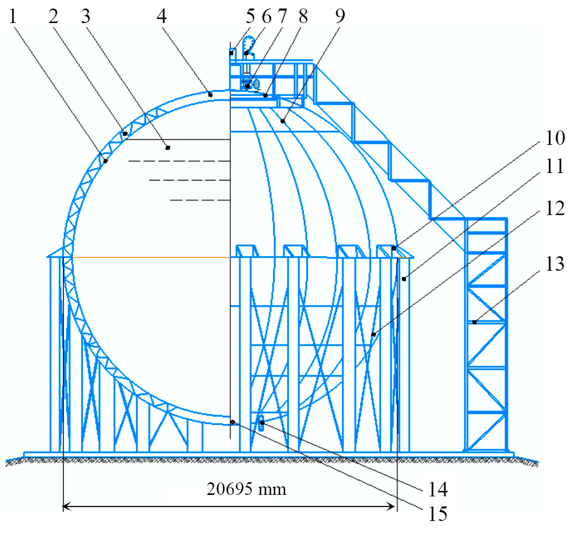
Inner layer of the reservoir is a shell assembled from individual steel sheets, cut at the factory from rolled sheets and then deformed to give a spherical curvature. Curvature radius of the sheets is equal to the radius of the shell. The inner layer is made of ON9 steel with 9 % nickel content, which is characterized by high elasticity required for storage of cryogenic liquids, with ultimate tensile strength σw = 640 MPa and yield strength σt = 595 MPa.
Filler is a girder system, which remains unbendable when the plates buckle and creates additional support fasteners for them. Wall deformations within each such field are considered independent. Girder filler is attached to the outer and inner layers with corners, which are welded to the shell in the welding points of the inner shell sheets.
Outer layer of the spherical reservoir is assembled from steel sheets 6 m long and 2 m wide so that the joint of the steel sheets falls on the stiffening beam, which is a corner. Thus, a welded joint is created for one-sided welding on the backing, where the backing is the corner shelf. Outer shell of the reservoir rests on the supports of pipes, interconnected by ties. Outer layer of the spherical reservoir is made of steel with durability class C345, grade 09G2S. Feature of this steel grade is a low cold brittleness threshold, good weldability and the required durability.
Geometric parameters of the inner, outer and middle layer of the reservoir wall are determined by calculation depending on the specified loads [2].
Creation of a numerical model in the SCAD software [7]. Reservoir wall models were divided into finite elements – prisms with size of 0.3×0.3×δi,where the thickness of the reservoir wall sheets is δi = 14 mm. Middle layer was taken as rod elements with a finite element length l = 0.42 m. Support posts were taken as rods with an outer diameter of 0.3 m with a wall thickness of 0.02 m.
Support tables connecting the reservoir wall with the support posts were taken as sheet elements with discretization on FE with a size of 0.1×0.1×0.02. In the lower parts of the support posts, links were introduced along the X, Y, Z axes of the orthogonal coordinate system.
Accumulation of loads and impacts. First steps in the calculation of a three-layer spherical reservoir are the determination of external loads, the construction of the design scheme, and also the establishment of the nature (shape) of the diagram for the application of these loads. It is possible to outline the loads acting on a three-layer spherical reservoir: dead weight of the metal structure of a three-layer spherical reservoir; snow load considered in three options; wind load; temperature climatic impacts; excessive pressure load; hydrostatic pressure load. Calculation of load combination options* showed that the maximum load acting on the spherical reservoir is 232.5 kPa.
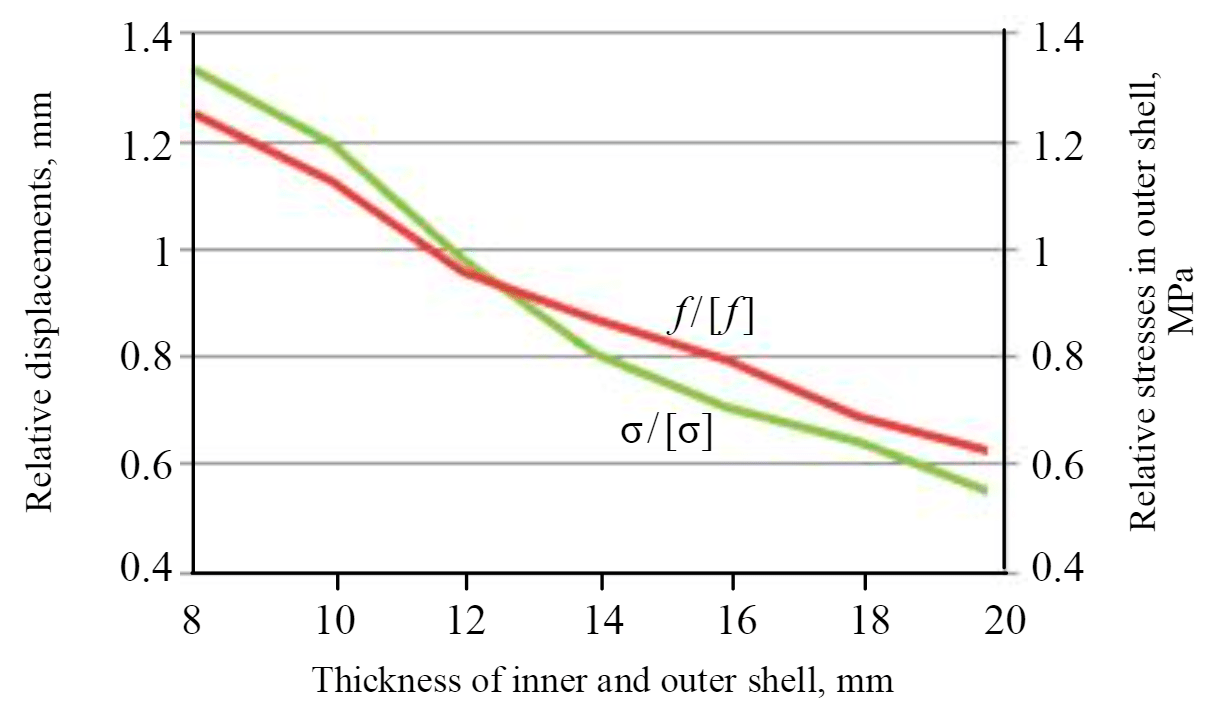
Dimensionless quantities were used for the study: the relative value of stresses σ/[σ] arising in the section of the element under the influence of loads and impacts, where [σ] are permissible stresses equal to: for steel grade 09G2S 190 MPa, for steel grade ON9 – 315 MPa [11].
In the reservoir model, it is assumed that the inner and outer walls are of equal thickness. Study of the wall thickness effect on the displacement and stress values is shown in Fig.2. Dependencies σ/[σ] = F(δ) and f/[f] = F(δ) show that both functions are practically linearly decreasing. Investigating the behavior of the two functions, we conclude that the optimal thickness of the shells taking into account the corrosion allowance is δ = = 14 mm.
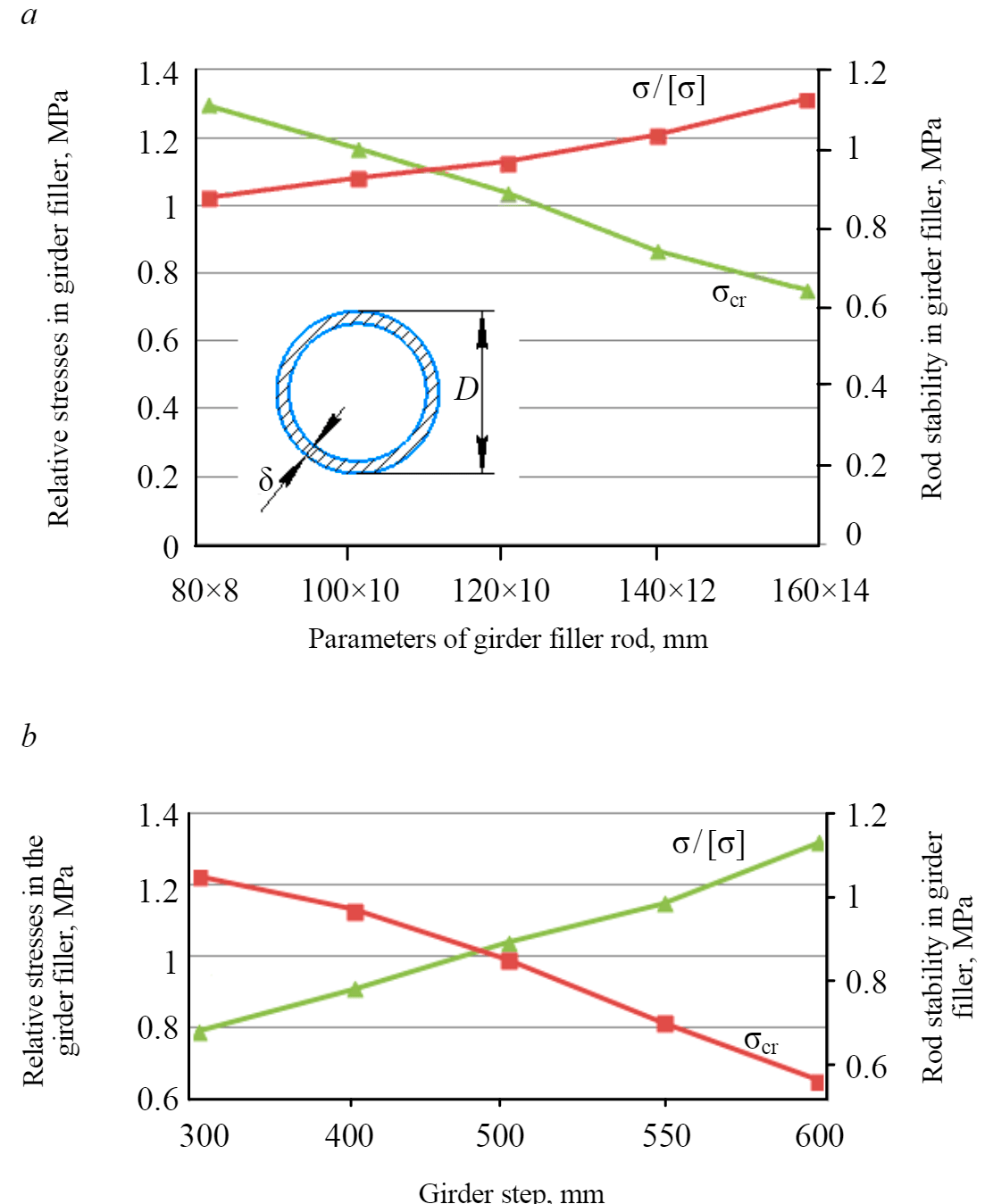
Because the product will be stored in the reservoir with a temperature of Т = –160 oС, it is necessary to provide thermal insulation. As thermal insulation, a layer of polyurethane foam with a thickness of B = 400 mm is taken, which has the following characteristics: density ρ = = 150 kg/m3, coefficient of thermal conductivity λ = 0.3∙106 W/m∙К. To exclude cold bridges, the ties in the girders are made of fiberglass grade VPS-30 with characteristics: density ρ = 1800 kg/m3,elastic modulus Е = 55∙103 MPa, linear expansion coefficient \(\ \alpha_t=8,3\cdot106{^oC^{-1}} \). Figure 3, a shows the dependence of the durability and stability of the girder filler rods on their parameters. According to the dependence, it can be concluded that the relative stresses in the girder filler decrease due to the increase in the diameter of the girder filler rod. Studying the behavior of the dependence, we conclude that the optimal parameter of the girder filler rod will be 120×12 mm.
For design reasons – a rational outline of the girder and ease of attachment – an angle of 45° is desirable. At small angles, the girder becomes too elongated, at large angles – high, which makes them bulky and uneconomical. Studying the dependence of the relative stresses on the angle between the wall and the girder filler rod, it can be stated that the angle equal to 45° is optimal for the girder.
Step size with which the girders should be installed can be derived according to the dependence of the relative stresses and stability of the rods on the step of placing the girders (Fig.3, b). It can be stated that the optimal step will be a distance of no more than 400 mm.
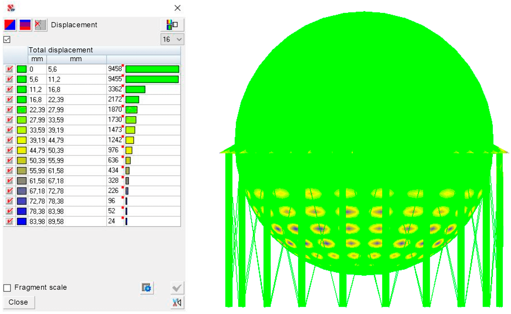
Discussion of the results. Result of the calculation is the color schemes for the distribution of the displacements of the outer wall, forces and stresses in the double-walled spherical reservoir. Calculation results are shown in Fig.4, 5. Fig.4 shows that the maximum displacements in the outer wall of the spherical reservoir do not exceed 90 mm.
Maximum permissible displacements for steel structures with a span of up to 30 m, according to the set of rules*: D/200 = 20000/200 = 100 mm, where D – diameter of the double-walled spherical reservoir, equal to 20000 mm. According to the calculation of the double-walled spherical reservoir, displacement of the structure is less than 100 mm, which is acceptable.
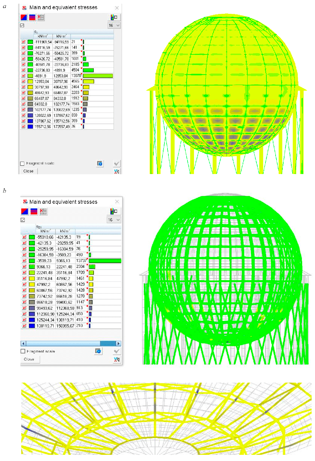
Figure 5, a shows the distribution of the main and equivalent stresses in the inner layer of the reservoir. It can be seen from the fig.5, а that compressive stresses in the shell plates reach 111.9 MPa, and the tensile stresses in the stiffeners are equal to 173.5 MPa.
Figure 5, b shows the distribution of the main and equivalent stresses in the middle layer of the reservoir. Maximum tensile stresses in the middle layer reach 150.9 MPa, and the maximum compressive stresses are 55.01 MPa. Moreover, tensile stresses are mainly observed in the lower zone of the middle layer, where the rods are adjacent to the bottom of the shell.
Table shows the comparative calculation results obtained by the FEM with the analytical calculation method. It can be seen that the error between the calculation results obtained by numerical (FEM) and analytical methods does not exceed 4.35 %.
Comparison of acquired results
| Analytical calculation | Numerical calculation | Error, % |
| Maximum displacements of the whole structure, mm | ||
| 93,1 | 89,58 | 4,07 |
| Maximum equivalent stresses of the inner layer, MPa | ||
| 180,78 | 173,56 | 4,16 |
| Analytical calculation | Numerical calculation | Error, % |
| Maximum equivalent stresses of the middle layer, kPa | ||
| 150,9 | 157,46 | 4,35 |
| Maximum equivalent stresses of the outer layer, MPa | ||
| 164,00 | 157,5 | 4,13 |
To study the metal content of a three-layer spherical reservoir, a comparative object is required – a single-layer spherical reservoir with an identical volume. Mass of the shell for a three-layer spherical reservoir with the calculated parameters is 110 tons, and the mass of the shell of a single-layer spherical reservoir with a wall thickness of 40 mm, manufactured at JSC “Uralkhimmash”, is 136 tons. When comparing the masses of double-layer and single-layer spherical reservoirs, mass of the developed design is less by 19 %.
Conclusion. Presented study was carried out within the framework of a linear problem statement. According to the proposed calculation method, it is possible to determine the optimal sections of the inner and outer shells, cross-sections of the ties between the shells, i.e. solve the problem in the first approximation. Results of the study have shown the promise of multilayer structures in reservoir construction.
However, in practice it is impossible to produce a shell with an ideal geometry. Thus, in a spherical reservoir for storing hydrocarbon raw materials there is a constructive non-linearity caused by the presence of weld-in pipes, hatches, and supporting elements. Geometric non-linearity characterizes residual welding deformations and faults of workers when assembling a reservoir from separate sheets. Currently, there is a technique for laser scanning of large reservoirs [13], which makes it possible to assess the deviations of the wall from the design position with a high resolution. Physical non-linearity in the reservoir wall is caused by the shaping of the sheet shell elements and their welding together. Thus, question of assessing the stress-strain state of shells under non-linearity conditions in the elastoplastic state of the metal is of scientific and practical interest. This will be the next object of our research.
Main findings. Method for building the structure of a double-walled spherical reservoir in the SCAD software has been developed, which allows calculating the SSS by the finite element method.
Numerical model of a double-walled spherical reservoir has been developed. It was found that to obtain calculation results with an error of P ≤ 5 % the size of the final element should not exceed 300×300×δ mm.
Design of a double-walled spherical reservoir is investigated. Design parameters have been established to ensure the operational reliability of the structure with a decrease in metal content in comparison with a single-wall reservoir by 19 %.
References
- Abashev D.R. Development of the model of elastoplastic deformation, fatigue criteria and methods for identifying material parameters of construction alloys: Avtoref. dis. … kand. fiz.-mat. nauk. Korolev: Tsentralnyi nauchno-issledovatelskii institut mashinostroeniya, 2016, p. 21 (in Russian).
- Abdullin I.N. Modeling a girder filler in a three-layer structure. Poisk effektivnykh reshenii v protsesse sozdaniya i realizatsii nauchnykh razrabotok v rossiiskoi aviatsionnoi i raketnokosmicheskoi promyshlennosti: Mezhdunarodnaya nauchno-prakticheskaya konferentsiya “Poisk effektivnykh reshenii v protsesse sozdaniya i realizatsii nauchnykh razrabotok v rossiiskoi aviatsionnoi i raketnokosmicheskoi promyshlennosti”, Kazan, 5-8 avgusta 2014, p. 307-312 (in Russian).
- Annin B.D., Volchkov Yu.M. Non-classical models for the theory of plates and shells. Prikladnaya mekhanika i tekhnicheskaya fizika. 2016. Vol. 57. N 5, p. 5-14. DOI: 10.15372/PMTF20160501 (in Russian).
- Golovanov A.I., Tyuleneva O.N., Shigabutdinov A.F. Finite element method in statics and dynamics of thin-walled structures. Moscow: Fizmatlit, 2006, p. 392 (in Russian).
- Gorshkov A.G., Starovoitov E.I., Yarovaya A.V. Mechanics of layered viscoelastoplastic structural elements. Moscow: Fizmatlit, 2003, p. 577 (in Russian).
- Gureeva N.A. Comparative analysis for the efficiency of using finite elements of triangular and quadrangular shapes in the calculations of shells. Avtoref. dis. … kand. tekhn. nauk. Volgograd: Volgogradskaya gosudarstvennaya selskokhozyaistvennaya akademiya, 2004, p. 28 (in Russian).
- Zelivyanskii E., Karpilovskii V., Kriksunov E. Transition from an architectural solution to a design scheme. SCADmaster. 2000. N 5, p. 40-43 (in Russian).
- Ishchanov T.R. Finite element analysis of the stress-strain state of thin shells taking into account the transverse shear for var-ious options of approximation of angular displacements: Avtoref. dis. … kand. tekhn. nauk. Volgograd: Volgogradskii gosudarstvennyi agrarnyi universitet. 2018, p. 21 (in Russian).
- Kiseleva R.Z. Calculation of layered plates and revolution shells based on three-dimensional finite elements without the as-sumption of normal deformation: Avtoref. dis. ... kand. tekhn. nauk. Volgograd: Volgogradskaya gosudarstvennaya selskokhozyaistvennaya akademiya, 2010, p. 20 (in Russian).
- Lazareva S.A. Approximation properties of the Fedorenko finite superelement method. Vychislitelnye tekhnologii. 2008. Vol. 13. Spetsialnyi vypusk 4, p. 75-81 (in Russian).
- Makarov D.A. Mathematical modeling of the processes of non-isothermal inelastic deformation and damage accumulation in structural materials. Avtoref. dis. … kand. fiz.-mat. nauk. Moscow, Moskovskii avtomekhanicheskii institut, 2005, p. 21 (in Russian).
- Kabrits S.A., Mikhailovskii E.I., Tovstik P.E., Chernykh K.F., Shamina V.A. General non-linear theory of elastic shells. St Petersburg: Izd-vo Sankt-Peterburgskogo universiteta, 2002, p. 388 (in Russian).
- Salnikov A.P Assessment of the stress-strain state of reservoirs by the state of ground-based laser scanning. Avtoref. dis. … kand. fiz.-mat. nauk. Moscow: Rossiiskii gosudarstvennyi universitet nefti i gaza im. I.M.Gubkina, 2016, p. 22 (in Russian).
- Semenov P.V Applied version of the theory of elastoplastic processes and the accumulation of material damage. Avtoref. dis. … kand. fiz.-mat. nauk. Moscow: Moskovskii avtomekhanicheskii institut, 2013, p. 21 (in Russian).
- Abot J.L., Daniel I.M., Gdoutos E.E. Contact Law for Composite Sandwich Beams. Journal of Sandwich Structures and Materials. 2002. Vol. 4. N 2, p. 157-173. DOI: 10.1177/1099636202004002705