Method of calculating pneumatic compensators for plunger pumps with submersible drive
- Ph.D., Dr.Sci. Doctoral student Ufa State Petroleum Technological University

Abstract
One of the most promising ways to improve the efficiency of mechanized oil production is a plunger pump with a submersible drive, which allows obtaining harmonic reciprocating movement of the plunger. In the pumping process of well products by plunger pumps, oscillations in the velocity and pressure of the liquid in the lifting pipes occur, which lead to an increase in cyclic variable loads on the plunger, a decrease in the drive life period and the efficiency of the pumping unit. To eliminate the pulsation characteristics of the plunger pump and increase the reliability indicators of the pumping unit (in particular, the overhaul period), pneumatic compensators can be used. A method for calculating the optimal technological parameters of a system of deep pneumatic compensators for plunger pumping units with a submersible drive, based on mathematical modeling of hydrodynamic processes in pipes, has been developed. Calculations of the forming flow velocity and pressure in the lifting pipes of submersible plunger units equipped with pneumatic compensators (PC) have been carried out. Influence of the PC technological parameters on the efficiency of smoothing the oscillations of velocity and pressure in the pipes has been analyzed. Non-linear influence of the charging pressure and PC total volume on the efficiency of their work has been established. Optimal pressure of PC charging, corresponding to the minimum pressure in the tubing during the pumping cycle for the considered section of the tubing, is substantiated. Two ultimate options of PC system placement along the lifting pipes are considered. In the first option, PC are placed sequentially directly at the outlet of the plunger pump, in the second - evenly along the lift. It is shown that the first option provides the minimum amplitude of pressure oscillations at the lower end of the tubing and, accordingly, variable loads on the pump plunger. Nature of the pressure and flow velocity oscillations in the tubing at the wellhead for both options of PC placement has similar values.
None
Introduction. Significant number of oil fields in Russia have entered a late stage of development, characterized by an increase in the share of high-viscosity oil reserves involved in development. Widespread use of waterflooding methods in formation pressure maintenance systems leads to an increase in water cut. Operation of wells in the water cut range of 45-70 % is accompanied by a number of complications associated with the creation of high-viscosity water-oil emulsions [6, 7]. Increase in product viscosity has a negative impact on the efficiency of mechanized operation of wells. In these conditions, an important task of the cost-effective development of oil fields operated by a mechanized method is the improvement of the used technical means that contribute to an increase in the efficiency of pumping equipment and an increase in the overhaul period (OP) [10, 11]. When operating wells with low and marginal flow rates, the most widespread are rod pumping units with plunger pumps (RPU), which are used on about 60% of the total number of oil wells in Russia [8, 13].
One of the most promising trends of increasing the efficiency of oil production by plunger pumps is the unit of a plunger pump, for which a linear (submersible) electric motor (LSEM) is used as a drive. Submersible drive allows obtaining direct harmonic reciprocating movement of the pump plunger, which helps to reduce the limitations in production associated with the presence of a pumping unit and a rod string, which is especially important when extracting high-viscosity products. In particular, the presence of a rod string leads to a decrease in the flow area of the tubing and an increase in hydraulic resistance, an increase in loads on the drive due to the viscous friction of the rods against the liquid [7, 15].
Statement of the problem. In the process of extracting well products by plunger pumps (RPU, LSEM), oscillations (pulsations) of the velocity and pressure of the fluid in the tubing and the flow line of the well occur. Main reasons for the occurrence of oscillations are: uneven nature of the flow rate of the plunger pump, influence of the viscous friction forces, compressibility and momentum of the extracted liquid. Excessive increase in pressure at a liquid shearing (especially a highly viscous one) during initial upward movement of the plunger, transmitted to the plunger in the form of a load pulse, leads to an increase in tension and a decrease in the service life of the drive and the efficiency of the pumping unit. In addition, pulsating nature of the pressure causes the appearance of cyclic alternating loads on the plunger, the amplitude of which reaches several MPa and naturally increases with increasing product viscosity. This contributes to increased fatigue wear of pumping equipment and has a negative effect on the reliability of the drive, causing a decrease in the OP.
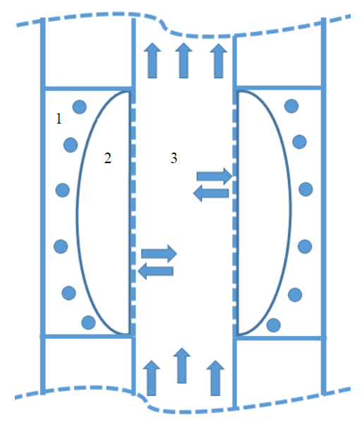
To eliminate the pulsation characteristic of the plunger pump and increase the OP of the pumping unit, pneumatic compensators (PC) can be used for both drilling pumps and rod units [1, 2, 5, 11]. They are designed to reduce the amplitude of pressure oscillations by equalizing the fluid flow rate in the tubing. In general, the pneumatic compensator includes a gas and a working chamber, separated by an impenetrable movable wall (for example, an elastic partition - a diaphragm can be used as a wall). Gas chamber of the pneumatic compensator is filled with gas at a certain pressure, the working chamber is connected with the tubing cavity (deep pneumatic compensator). With an increase in the flow rate and pressure in the pipes, the gas chamber of the pneumatic compensator is compressed, and part of the liquid flows into the vacated volume of the PC working chamber. With a decrease in the flow rate and pressure in the pipes, the pneumatic compensator gives off a portion of the liquid into the pipes, thus equalizing the flow rate in the tubing above the place where the pneumatic compensator is installed. Efficiency of pneumatic compensators in the general case is determined by a number of parameters: pressure, gas volume in the PC gas chamber, temperature conditions in the range of the pneumatic compensator location, composition and characteristics of the injected gas, rheological properties of the extracted product, etc. In this work, when calculating pneumatic compensators, following assumptions are made: compression and expansion of gas in the gas chamber occurs according to the isothermal law; the hydraulic resistances arising from the overflow of the extracted liquid between the working chamber of the PC and the tubing cavity, as well as cavitation effects resulting from the influence of the variable local pressure of the liquid are neglected; volumetric compression ratio of the extracted fluid is taken constant along the entire length of the tubing; it is assumed that the temperature of the fluid in the tubing increases in depth linearly with a constant geothermal gradient. As a standard PC sample, a cylindrical coaxial diaphragm pneumatic compensator is considered, the movable element of which (elastic diaphragm) moves in the space between the tubing and the outer pipe (Fig.1).
The paper proposes a computational method for determining the optimal technological parameters of deep PC, based on mathematical modeling of hydrodynamic processes in lifting pipes.
Modeling the dynamics of the flow velocity and pressure in the lifting pipes of LSEM units. To solve the problem of a justified calculation for the optimal technological parameters of pneumatic compensators, a two-stage method is proposed. At the first stage, mathematical modeling of the fluid movement in the lifting pipes during fluid extraction by the LSEM is carried out; based on the simulation results, the curves of the dynamics of the fluid velocity and pressure in various sections of the lifting pipes corresponding to the location of the pneumatic compensator are constructed. At the second stage, based on the obtained curves, the technological parameters of pneumatic compensators are calculated.
Modeling of unsteady hydrodynamic processes in the gas-liquid flows in pipes, as a rule, is based on the numerical solution of the Navier – Stokes equations. Many investigations of Russian and foreign authors are devoted to the theoretical foundations of multiphase flows in a well [3, 4, 14 - 17]. To calculate the distribution of the flow velocity and pressure in the lifting pipes during the LSEM operation, a mathematical model for the unsteady flow of the mixture in the lifting pipes was developed, based on the laws of conservation of mass and pulse for a gas-liquid flow [9]:
where ρ, v – density, volume fraction and velocity of the pumped mixture, respectively; l – length of pneumatic compensator; S – internal cross-sectional area of pipes; p – pressure; τ – shear stresses on the pipe wall; П – perimeter of liquid-to-wall contact; gz> – projection of the gravity constant along the coordinate z; velocity of mass flow between the lifting pipes and the working cavity of the pneumatic compensator, determined on the assumption that the compression and expansion processes of the PC gas chamber are isothermal according to the Boyle – Mariotte law
p0,V0 – initial pressure and volume of the PC gas chamber, respectively. The value numerically equal to the product p0,V0, is called PC energy intensity.
It follows from formula (2) that with an increase in energy intensity, the mass and volume of fluid that can be received and given off by the pneumatic compensator increases per unit time. Model of a weakly compressible fluid is used to describe the liquid phase [17]. Boundary conditions are set as follows: at the inlet – the fluid velocity at the pump outlet, determined by the velocity of the pump plunger, and at the outlet – the specified pressure at the end of the oilfield pipeline. Result of the numerical solution for the system is the change in time of the flow velocity and pressure in an arbitrary section of the lifting pipes [9, 17].
Features of the proposed model are: detailed consideration of the nature of the distribution for the flow rate of plunger pump for the LSEM – in the half-cycle of suction, the fluid velocity at the pump outlet changes according to a harmonic law, in the pumping phase is zero; presence of source terms associated with mass flow between the cavities of the lifting pipes and pneumatic compensators.
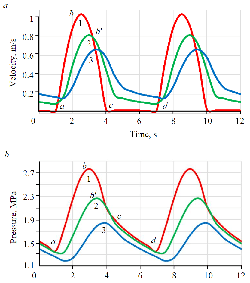
Figure 2 shows the results of calculating the dynamics of the fluid velocity and hydrodynamic pressure (static pressure at a given depth is taken as zero line) in the tubing of the model well. Geological, technical and technological parameters of its work: tubing diameter is 62 mm; plunger diameter is 57 mm; tubing length is 1000 m; fluid viscosity is 0.1 mPa∙s; fluid density is 900 kg/m3; fluid compressibility is 1500 MPa-1; temperature at the wellhead is 20 0С; geothermal gradient is 0,01 0С/m; stroke length 2,2 m; stroke number is 10 min-1; flow line length is 1000 m.
Section аc (рис.2, а) corresponds to the suction phase and the forward movement of the liquid and the pump plunger upward, and section cd characterizes the pumping phase, in which the fluid velocity at the lower end of the tubing, except for the interval of plunger rod movement, is zero.
Curves for the dynamics of flow velocity and pressure at different depths are phase shifted relative to each other (in particular, points b and bʹ), which is due to the influence of the fluid compressibility and the forces of hydrodynamic friction. With decreasing depth, the fluid velocity and pressure are equalized in half-cycles of pumping. Curves for changes in the hydrodynamic pressure б) show that the mean value of the integral pressure for the pumping phase exceeds the value of the static one, and the hydrodynamic pressure increases with increasing depth along the axis of the well. Taking into account these features for the formation of the velocity and pressure fields allows for a justified calculation of pneumatic compensators as part of the LSEM.
Methodology for calculating the geometric and technological parameters of the pneumatic compensator system. Technological parameters of the deep PC system include: charging pressure of pneumatic compensators (pressure of the gas previously injected at the surface into the PC), number of pneumatic compensators of a standard sample (see Fig.1), which determines the total volume of gas chambers, and the interval of their installation along the tubing string. Known methods for calculating pneumatic compensators [1, 2, 5, 12] are more approximate, since they do not take into account the physical principles for the forming of pressure and fluid velocity oscillations in pipes, as well as the design features of the considered type of deep pneumatic compensators representing cylindrical chambers.
It is assumed that the operation of pneumatic compensators in the well occurs under isothermal conditions, i.e. an increase in pressure in the PC working chamber leads to a decrease in the volume in the gas chamber. Equation for isothermal compression of gas in the i-й chamber
where \( P'_{i0}=P_{i0}\frac{zT_i}{T_{i0}} \) – pressure in the PC gas chamber in well conditions; Ti0, Ti – ambient temperature during charging and in well conditions, respectively; Pi0, Vi0 – charging pressure (pressure of the gas previously injected at the surface into the PC) and the total volume of pneumatic compensators located at the i depth along the tubing, respectively; ΔPi, ΔVi – change in pressure and volume of gas chambers, respectively. Given the value of the desired amplitude of pressure oscillations after smoothing ΔPi, one can determine the total volume of pneumatic compensators for the i interval from formula
Velocity of fluid movement at the lower end of the tubing in the suction phase is determined by the velocity of the pump plunger, and in the pumping phase is zero:
where t – time; S, n, T=n-1 – stroke length, frequency and period of the plunger stroke, respectively; dp, dt – plunger diameter and tubing inner diameter, respectively.
To equalize the flow rate of the plunger pump, it is necessary that during the period of increasing velocity and pressure, a certain volume of liquid flows into the chamber, and during the period of decreasing the equivalent volume is given off by the chamber back into the lifting pipes. Mentioned above allows for a constant average integral flow velocity above the chamber
Time interval t1-t2, in which the instantaneous velocity of the fluid exceeds the mean integral, is determined from the expressions:
Volume of liquid ΔVpc, which must be accumulated in the working chamber of pneumatic compensators during the period of increasing flow velocity and pressure, is determined by the difference between the instantaneous and average integral pump flow rate during the period t1-t2
When using a deep PC system, volume of liquid is the algebraic sum of the volumes accumulated in the gas chambers of each pneumatic compensator. Total number of PC in the system and the interval of their placement along the tubing string is generally determined by solving the equation
where N – number of PC placement intervals along the tubing string
When determining the interval of the placement for the PC system, two ultimate options can be considered.
Option 1. Pneumatic compensators are installed in series at the outlet of the plunger pump. This makes it possible to increase the total volume of the “pneumatic gas buffer” of the PC system and thereby ensure the uniform nature of fluid movement in the lifting pipes in each of the pumping half-cycles. Since pneumatic compensators are installed close to each other, their technological parameters coincide; in this case, from formula (9), the following expression can be obtained for calculating the number of standard PC at the pump outlet:
where Vpc – standard PC volume.
Option 2.. Pneumatic compensators are installed evenly along the lift. It is assumed that in this case, the PC system makes it possible to facilitate the shearing conditions for the liquid in the tubing: at the beginning of the upward plunger stroke, the liquid column enclosed between the pump and the first chamber is initially set in motion. Liquid partially fills the volume of the first chamber and compresses the gas located there. After reaching the ultimate value of the pressure in the first chamber, the second section is set in motion, located between the first and second chambers, etc. Interval movement of the liquid column in the tubing allows reducing extreme loads on the pumping equipment at the beginning of the upward plunger stroke [5]. With a known value of the interval for PC placement, ΔLpc (taking into account that each of the pneumatic compensators of the system receives an equal amount of liquid), the number of PC located in the i interval is calculated according to the formula:
where L – length of the tubing string, м.
Influence of technological parameters of pneumatic compensators on the efficiency of smoothing oscillations in flow velocity and pressure. Effectiveness of reducing oscillations in flow velocity and pressure is determined by two key parameters: pressure and volume of gas in the PC gas chamber (and, accordingly, PC energy intensity). As analyzed technological parameters that affect the amplitude of oscillations in the flow velocity and pressure, the following are considered: charging pressure and the total volume of pneumatic compensators (the volume of one PC means the maximum possible volume of the PC gas chamber, determined by its geometric characteristics). Resulting volume of the PC system is regulated by changing the number of standard pneumatic compensators installed in the well. Cylindrical coaxial diaphragm pneumatic compensator is considered as a standard PC unit, the movable element of which (elastic diaphragm) moves in the space between the tubing (outer diameter 73 mm) and the outer pipe (diameter 100 mm), the length of one chamber is 1 m. Operation of the LSEM is simulated with deep PC system located at the outlet of the plunger pump.
With an increase in the PC total volume, the energy intensity of the pneumatic compensator system increases, the amplitude of oscillations in the flow velocity and pressure naturally decreases (Fig.3), and as the number of PC increases, the smoothing rate of pressure pulsations decreases. To assess the degree of pressure equalization in the pipes, the concept of pressure pulsation coefficient is used [1, 2, 5]
where pmax, pmin, pmid – maximum, minimum and average integral pressure per pumping cycle, respectively.
In the considered example, the initial pulsation coefficient is 0.67 (67 %), the oscillation range (difference between the maximum and minimum value) is 1.31 MPa. With an increase in the resulting volume of the gas chambers in the PC system from 50 to 200 m3 the pulsation coefficient decreases from 44 to 19 %, the range of pressure oscillations – from 0.87 to 0.37 MPa. Since with an increase in the PC total volume, the amplitude of pressure oscillations gradually decreases, the working stroke of the diaphragm and the effective volume of liquid taken by the PC decrease, therefore, the relationship between two values (the pulsation coefficient and the total volume of pneumatic compensators) is close to hyperbolic.
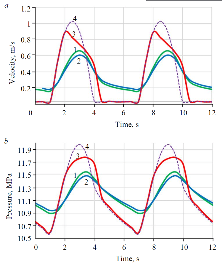
Fig.4 shows the effect of the charging pressure of pneumatic compensators on the configuration of barograms. Initially, an increase in the charging pressure from 5.3 to 7 MPa (from 8 to 10.5 MPa under well conditions, curves 1 and 2 in Fig.4, (б)) leads to a decrease in the amplitude of pressure oscillations (pulsation coefficient decreases from 0.33 to 0.27, oscillation range – from 0.65 to 0.54 MPa): at a lower charging pressure, the fluid pressure in the tubing, during the pumping cycle exceeding the charging pressure, causes a constant compression of the gas chamber, and, consequently, a decrease in the working stroke of the PC diaphragm and the effective volume of fluid taken by the PC.
With an increase in the charging pressure from 10.5 to 11.5 MPa (converted to well conditions, curves 2 and 3 in Fig.4, (б)), the amplitude of pressure oscillations increases, and the shape of the barogram changes. If the pressure in the tubing decreases to a value lower than the pressure of the PC charging (converted to well conditions, taking into account the temperature change in the interval of the PC location), during the expansion of the gas chamber the diaphragm completely adjoins the inner wall of the pneumatic compensator, which is due to its design features (see Fig.1), and the flow rate of the pneumatic compensator stops. Normal operation of the pneumatic compensator is achieved only under the condition that the pressure in the tubing cavity exceeds the PC charging pressure.
Thus, an excessively high charging pressure as well as an excessively low one has a negative impact on the PC performance. Based on this, it is rational to set the optimal charging pressure equal to the minimum pressure in the tubing during the pumping cycle, i.e. the sum of the static pressure and the minimum hydrodynamic pressure in the tubing during the PC operation (i.e., approximately 10.9 MPa, as follows from Fig.4, (б)).
It should be noted that the existing methods for calculating the technological parameters of pneumatic compensators do not take into account the physical principles of the oscillations formation in the flow velocity and pressure in pipes during PC operation. In particular, in works [1, 12] the initial pressure in the pneumatic compensator (pressure of the PC charging in well conditions) is recommended to be selected in the range of 25-80 % of the maximum pressure during the pumping cycle, which in the considered case corresponds to the pressure range of 3-9.5 MPa and less than the optimal value (10.9 MPa) obtained according to the developed method.
Analysis of calculation results. Proposed method was used to calculate the technological parameters of the deep PC system for a model well (Table).
Geometric and technological parameters of the pneumatic compensator system
| PC parameter | Option 1 | Option 2 (wellhead-pump outlet) |
| Charging pressure, MPa | 7,3 | 1,3-7,3 |
| Total volume, m3 | 0,095 | 0,003-0,019 (∑ = 0,065) |
| Energy intensity, MJ | 1,04 | 0,005-0,020 (∑ = 0,56) |
| Number in the system | 26 | 1-5 (∑ = 20) |
| Placement interval, m/td> | – | 200 |
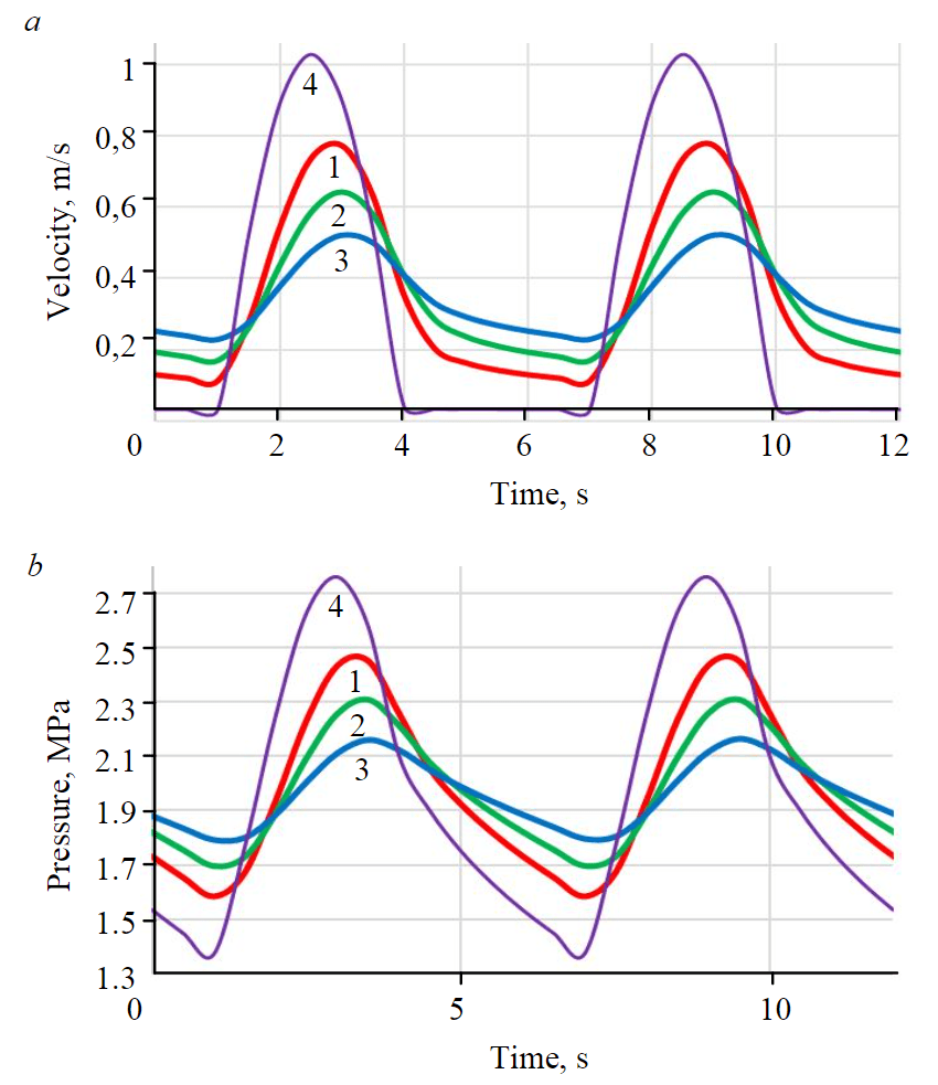
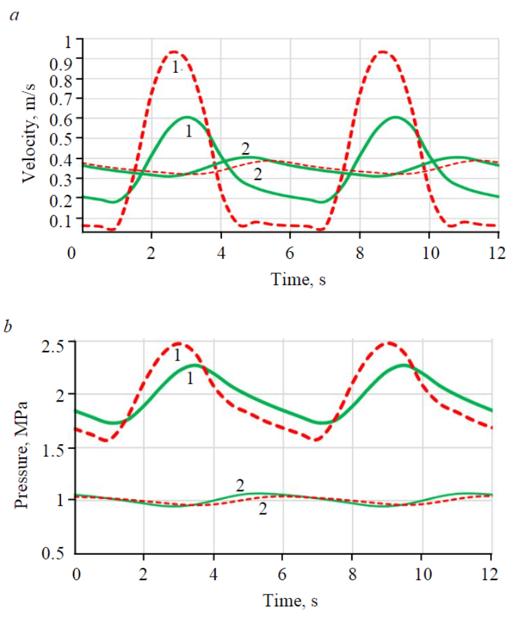
Figure 5 shows the curves of changes in time of the flow velocity and hydrodynamic pressure for two sections of the tubing – at the surface near the wellhead and at the lower end of the tubing.
As the fluid rises in the tubing, the fluid pressure and, accordingly, the required pressure for PC charging, as well as the number of PC in a given interval, decreases, which is due to a decrease in both the hydrostatic component and pressure losses due to hydrodynamic friction. As a result, in option 2 (even placement), the total number (by 36), the total volume (by 23) and the energy intensity of the PC system (by 46 %) are less than in option 1 (PC placement at the lower end of the tubing at the outlet of the plunger pump). Considering reduction of oscillations in the flow velocity and pressure at the outlet of the pump, and, accordingly, variable loads on the plunger, option 1 is preferable (pressure pulsation coefficient in option 1 is 0.28, in option 2 – 0.54, oscillation range reaches 0.54 and 0.91 MPa, respectively). Nature of pressure and velocity oscillations in the tubing at the wellhead for both options of PC placement has similar values. This is due to the fact that, in option 2, the formation of the flow velocity and pressure in the tubing at the wellhead is due to the operation of the entire system of deep PC, and in the lower part of the tubing, first of all, by the operation of the corresponding PC located below the investigated pipe section. In option 1, the entire PC system is located at the pump outlet and allows more effective smoothing out pressure and flow velocity oscillations in the entire tubing interval.
Conclusion
1. Method has been developed for calculating the optimal geometric dimensions, placement interval and technological parameters of a system of deep pneumatic compensators for plunger units with a submersible drive, based on mathematical modeling of hydrodynamic processes in lifting pipes with detailed consideration of the mechanisms for the formation of unsteady flow velocity and pressure fields during product pumping.
2. On the basis of theoretical calculations for the formation of the flow velocity and pressure in the lifting pipes of submersible plunger units equipped with pneumatic compensators (PC), influence of PC technological parameters on the efficiency of smoothing the velocity and pressure oscillations was analyzed. It is shown that the degree of pressure pulsations smoothing increases with an increase in the volume of the gas chambers in the pneumatic compensators, and the relationship between the two values (pulsation coefficient and total volume of the pneumatic compensators) is close to hyperbolic.
3. Non-linear influence for charging pressure of the pneumatic compensators on their operating efficiency is shown. An excessively high charging pressure, as well as an excessively low one, has a negative effect on the PC performance. It is recommended to set the optimal charging pressure equal to the minimum pressure in the tubing during the pumping cycle, i.e. the sum of the static and minimum hydrodynamic pressure in the tubing during the operation of pneumatic compensators.
4. Two ultimate cases for the placement of the pneumatic compensator system along the lifting pipes are considered. In option 1, pneumatic compensators are placed in series directly at the outlet of the plunger pump, in option 2 – evenly along the lift. It is shown that if considering reduction of the oscillations in the flow velocity and pressure at the pump outlet and, accordingly, variable loads on the plunger, option 1 is more optimal. This is because the formation of the flow velocity and pressure in the tubing in option 1 is due to the operation of the entire system of deep PC, and in option 2 – to the operation of certain number of the PC located below the investigated pipe section.
References
- Zotov A.N., Timashev E.O., Urazakov K.R. Methods of Pressure Damping upon the Ostium of Sucker Rod Pumps. Petroleym Engineering. 2018. Vol. 16. N 6, p. 56-64. DOI: 10.17122/ngdelo-2018-6-56-64 (in Russian).
- Zotov A.N., Urazakov K.R., Dumler E.B. Simulation of operation of pneumatic compensator with quasi-zero stiffness in the electric centrifugal submersible pump unit. Journal of Mining Institute. Vol. 229, p. 70-76. DOI: 10.25515/PMI.2018.1.70
- Grigoriev B.S., Eliseev A.A., Pogarskaya T.A., Toropov E.B. Mathematical Modeling of Rock Crushing and Multiphase Flow of Drilling Fluid in Well Drilling. Journal of Mining Institute. 2019. Vol. 235, p. 16-23. DOI: 10.31897/PMI.2019.1.16
- Topolnikov A.S., Urazakov K.R., Vahitova R.I., Saracheva D.A. The method of calculation of parameters of jet pump attached to joint operation with submersible electric pump. The electronic scientific journal “Oil and Gas Business”. 2011. N 3, p. 134-146 (in Russian).
- Urazakov K.R., Bogomolnyi E.I., Seitpagambetov Zh.S., Gazarov A.G. Pump extraction of high-viscosity oil from deviated and watered wells. Moscow: Nedra, 2003, p. 303 (in Russian).
- Vdovin E.Yu., Lokshin L.I., Lure M.A., Korotaev A.D., Timashev E.O. New technologies for the operation of low flow rate and periodic well stock. Inzhenernaya praktika. 2017. N 11, p. 40-43 (in Russian).
- Bakhtizin R.N., Urazakov K.R., Timashev Je.O., Belov A.E. A New Approach of Quantifying the Technical Condition of Rod Units with the Solution of Inverse Dynamic Problems by Multidimensional Optimization Methods. Oil Industry. 2019. N 7, p. 118-122. DOI: 10.24887/0028-2448-2019-7-118-122 (in Russian)
- Urazakov K.R., Abramova E.V., Topolnikov A.S., Minnigalimov R.Z. Technology for increasing oil from low-productiv wells. The electronic scientific journal “Oil and Gas Business”. 2013. N 4, p. 201-211 (in Russian).
- Timashev E.O., Urazakov K.R. Dynamics of Flow Rate and Pressure in the Tubing of Plunger Pumps with Downhole Drive. Journal “Problems of Gathering, Treatment and Transportation of oil and oil products”. 2019. N 4, p. 82-88. DOI: 10.17122/ntj-oil-2019-5-45-55 (in Russian).
- Urazakov K.R., Molchanova V.A., Topolnikov A.S. Mathematical model of a rod unit with an ejector for pumping gas from the annulus space. Neft. Gaz. Novatsii. 2007. N 6, p. 54-60 (in Russian).
- Urazakov K.R. Mechanized oil recovery: a collection of inventions. Ufa: Neftegazovoe delo, 2010, p. 329 (in Russian).
- Urazakov K.R., Timashev Je.O., Tukhvatullin R.S. Wellhead Pneumatic Compensator of the Sucker-Rod Pumping Unit. Territorija NEFTEGAS (Oil and Gas Territory). 2017. N 12, p. 60-64 (in Russian).
- Bakhtizin R.N., Urazakov K.R., Latypov B.M., Ishmuhametov B.H. Fluid leakage in a sucker-rod pump with regular micro-relief at surface of the plunger. Petroleym Engineering. 2016. Vol. 14. N 4, p. 33-39 (in Russian).
- Brill J.P., Mukherjee H. Multiphase flow in wells. Society of petroleum engineers. 1999. Vol. 214, p. 215.
- Bakhtizin R.N., Urazakov K.R., Ismagilov S.F., Topolnikov A.S., Davletshin F.F. Dynamic model of a Rod Pump Installa-tion for inclined wells. SOCAR Proceedings. 2017. N 4, p. 74-82. DOI: 10.5510/OGP20170400333
- Leonov E.G., Isaev V.I. Applied Hydroaeromechanics in Oil and Gas Drilling. Hoboken, New Jersey: John Wiley & Sons, Inc., 2010, p. 474.
- Pletcher R.H., Tannehill J.C. Computational Fluid Mechanics and Heat Transfer. Washington: CRC Press, Taylor & Francis Group, 2013, p. 705.