
Prediction of the limit state and dilatancy of rocks around mine workings
- 1 — Ph.D., Dr.Sci. Head of Department Empress Catherine ΙΙ Saint Petersburg Mining University ▪ Orcid
- 2 — Ph.D., Dr.Sci. Professor Empress Catherine ΙΙ Saint Petersburg Mining University ▪ Orcid
- 3 — Ph.D. Associate Professor Empress Catherine ΙΙ Saint Petersburg Mining University ▪ Orcid
- 4 — Ph.D. Associate Professor Empress Catherine ΙΙ Saint Petersburg Mining University ▪ Orcid
Abstract
The goal of this study is to enhance the method for predicting geomechanical processes during mine working construction in an elastoplastic rock mass with dilatancy. We present the results of experimental research into the volumetric strength of rocks and the specifics of volumetric strain development under plastic shear. We demonstrate rock dilatancy and provide diagrams showing how volumetric plastic shear strains change at different levels of accumulated shear strains. We process the rock testing results using A.N.Stavrogin’s plasticity condition. We propose a new analytical solution for predicting the stress-strain state of the rock mass in areas with inelastic strains, based on A.N.Stavrogin’s plasticity condition. This includes equations for modelling the limit state zone of rock around a mine working. We introduce an algorithm for predicting the stress-strain state of the rock mass. We investigate how the size of the limit state zone around a mine working relates to rock dilatancy parameters, lateral stress coefficient, and working depth. We examine how contour displacements develop for a circular mine working under plane strain conditions, considering various plasticity parameters and rock dilatancy indicators. We implement A.N.Stavrogin’s plasticity condition in the Abaqus software package. Our research results help define the scope of the analytical solution. The solution remains physically meaningful only when the limit state zone forms around the entire perimeter of the mine working. The proposed numerical approach removes this limitation. It applies to any geomechanical state of the rock mass and to mine workings with any cross-sectional shape.
The work was financially supported by a grant from the Russian Science Foundation (Project N 23-17-00144).
Introduction
With increasing depth of mineral deposit exploitation, a decrease in the stability of rock exposures is observed [1-3], accompanied by the development of plastic strains in the limit state zone [4]. The solution to the problem of predicting the limit state zone and displacements around rock exposures located in an elastoplastic rock mass is of considerable interest in the development of underground space and mineral deposits [3, 4]. This involves: studying the mechanical properties of rocks [5-8]; investigating the rock mass characteristics [9, 10], formulating new rock strength criteria [11-13]; developing models to predict the geomechanical state of the rock mass around mine workings – both based on its natural stress state and taking into account internal pressure that may arise in the mined-out area. Based on the solutions obtained, measures are developed to bring rock exposures to a stable state [14].
The modelling of limit state zones around mine workings in a plane‑strain formulation reduces to solving two-dimensional elastoplastic problems [15, 16] with a priori undetermined boundary that separates the elastic and plastic regions in the rock mass. In these regions, the strain of the media is governed by different sets of equations. Analytical solution of such problems poses certain difficulties, since the shape and size of the plastic zone are not known beforehand and must be determined as part of the solution [17-19].
The first exact solution to the elastoplastic problem of stress distribution around a circular hole in an infinite plane was provided by L.A.Galin. This solution can be used to estimate limit state zones around a working in a rock mass subjected to constant stresses at infinity and with normal forces applied at its contour. Displacements in the plastic zone for Galin’s problem were determined using D.D.Ivlev’s method of a small parameter. N.I.Ostrosablin obtained an exact solution of the system of equations for displacements in this zone. Further studies of the plane elastoplastic problem involved changing the hole shape from circular to elliptical.
Most existing analytical and semi‑analytical solutions for predicting the size of limit state zones around a mine working are based on considering an infinite plane in the vicinity of a rock exposure as an elastoplastic medium, using the Coulomb plasticity condition [20, 21]. A number of analytical solutions were obtained for predicting the stress-strain state using nonlinear strength criteria for rocks [22-25]. The main focus was on the formation of the stress-strain state around a circular mine working. Solution to this problem was derived for an ideal elastoplastic medium [26-28], an elastoplastic medium accounting for isotropic hardening or softening [29-31]. Analytical dependencies were presented for predicting the size of the limit state zone and strains of the rock exposure contour – both for small and large strains [32, 33]. Some studies addressed the prediction of the stress-strain state around a working located in an anisotropic rock mass [34] or in a viscoplastic medium [35]. Recent works found wide application in predicting the stress-strain state of rock masses prone to large strains. Specific problems include predicting the stress-strain state of a rock mass around non-circular tunnels [36] or predicting the state around twin tunnels [37].
Despite these results, analytical solutions were obtained for simple strength conditions, predominantly linear ones. It is known that many rocks exhibit nonlinear envelopes of limit Mohr’s circles. This fact should be considered when performing geomechanical predictions. The present work focuses on deriving an analytical solution and developing a numerical model to predict the stress-strain state of a rock mass around a circular mine working, based on A.N.Stavrogin’s strength criterion.
Research methods
A.N.Stavrogin’s strength criterion
The shape of the envelope of the limit Mohr’s circles for rock is curvilinear, which is related to the complex nature of its failure under different types of stress states. In special cases, the envelope can be simplified and represented as a linear relationship, referred to as the Coulomb strength criterion. To describe the nonlinear envelope, [25] proposes to use various curves, including a parabola, an exponential function, a cycloid, and others – either in combination with straight-line segments or without them. A.N.Stavrogin proposed strength criteria for the limit elastic state and the strength limit of the following form:
where equation (1) is the condition for elastic state limits; equation (2) is the condition for strength limits; are the elastic and strength limits; τe0, τp0 are constants representing the elastic limit and strength limit under uniaxial compression; B, A are constants reflecting the hardening of rocks with increasing hydrostatic pressure; C=σ3/σ1 is a parameter characterizing the type of stress state.
From the equality condition τe=τp, we find the coordinate:
The value Cp, substituted into (1) or (2), allows obtaining the second coordinate of the intersection point of the limit curves lnτp. After that, we can calculate the tensile strength using the formula
Statement of the problem of predicting the limit state zone around a mine working
The prediction of the limit state zone around a mine working is considered in the plane strain formulation (Fig.1). The size of the mine working is taken as r0, and the size of the computational domain is R >> r. The external loading on the boundaries of the computational domain is specified as pressure equal to γH (vertical component) and λγH (horizontal component). As a result of the external loading, a stress state forms in the computational domain, defined by the components of the stress tensor σr, σθ, τrθ. When determining the size of the limit state zone, it is assumed that the zone size is RL. In this case, the analytical solution is meaningful only if the limit state zone fully encompasses the contour of the mine working. The numerical solution does not have such limitations.
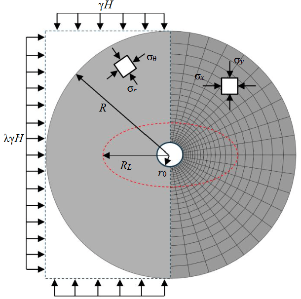
Fig.1. Problem statement for predicting the stress-strain state of a rock mass in the vicinity of a mine working: on the left – the computational scheme; on the right – the finite element model; σx, σy – components of normal stresses; σθ, σr – tangential and radial stresses; R – radius to the outer boundary of the computational domain (R >> r); RL – size of the limit state zone
A.N.Stavrogin’s strength criterion is not implemented in software products for strength computations using numerical analysis methods. Plasticity conditions for geomaterials in such software are limited to linear forms. To incorporate A.N.Stavrogin’s plasticity condition, a special procedure must be developed. This procedure should update the stress state during elastoplastic strain of the material. By dividing A.N.Stavrogin’s nonlinear plasticity condition into a set of linear segments, its implementation can be achieved without developing a full model that includes all procedures characteristic of the numerical theory of plastic flow.
As the linear plasticity condition, the widely validated Coulomb – Mohr plasticity criterion is adopted:
where c is the adhesion; φ is the internal friction angle.
To convert A.N.Stavrogin’s strength parameters to equivalent Coulomb strength parameters (i.e., equivalent cohesion and internal friction angle), we use an approximation of the exponential envelope of the limit stress circles (2) by a piecewise-linear function. The accuracy of the approximation is determined solely by the number of points selected on the original exponential envelope.
For two consecutive points on the exponential envelope, which represent the initial and final points of a single linear segment on the approximating piecewise-linear envelope (with constant values of cohesion and internal friction angle), the values are determined according to the expressions:
where τM, τN, σM, σN are the coordinates of adjacent points M and N on the exponential envelope.
Research results
Analytical solution for predicting the stress-strain state of a rock mass using A.N.Stavrogin’s criterion around a circular mine working
Research [26] considers the issues of modelling the zone of plastic strains around a circular mine working for the case of a hydrostatic natural stress state. The boundaries of the limit state zone are determined by A.N.Stavrogin’s plasticity condition.
The size of the limit state zone is obtained using the method of a small parameter and can be written as:
where ε=0.5(1-λ); θ is the angular coordinate;
λ1=0.5(1+λ); H – depth of the working; γ – specific weight of the rock mass; R0 – radius of the working;
.The value k=a/r02 is determined from the equation
In formulas (9) the constant С1 is equal to
τ1 is determined from the equation
where p0 is the support back-pressure.
The stress components in the elastic zone around the working are expressed as:
where a, b, d2 are coefficients accounting for the boundary conditions.
Let us now proceed to determine the displacements around a mine working for the case of a geostatic natural stress state, when the lateral pressure coefficient λ differs from unity. In this case, displacements in the rock mass around the working depend on the radial coordinate r and the angular coordinate φ. When solving the problem, we restrict ourselves to a linear approximation of dilatancy.
The dilatancy condition in polar coordinates can be written as:
where u and v are the radial and circumferential displacements.
Experimental data show that for some rock types, the coefficient d in linear approximation varies from 0 to –0.86.
Due to isotropy, the volume change during plastic strain of rocks does not depend on direction and does not affect shear strains. Therefore, in the limit zone near the working contour, the shear strains
Then, to determine the displacements u and v, we must solve equations (16) and (17). For this, we use the semi-inverse solution method. Restricting ourselves to a first approximation for the small parameter ε, we will seek the displacements in the form:
where u0 is a constant function; f (r), φ(r) are the desired functions.
By introducing functions (18) and (19) into equations (16) and (17) and equating expressions for the same powers of ε, we obtain the system
Let us reduce this system of equations to the Euler differential equation:
where and the characteristic equation is written as
has roots
Given that the coefficient d, according to experimental data, is in the range -√3/2<d≤3, we will consider only the case of complex roots. Then the function φ(r) of equation (21) will be written as:
Determining from equation (25) φ(r) and substituting (25) into (18) and (19), we write the displacements u and v as follows:
where
In the elastic zone, stresses and displacements are related by Hooke’s law:
where E, ν is the modulus of elasticity and Poisson’s ratio of the rock mass, respectively.
We find the displacements in the specified zone by introducing stresses (13) and (14) into (28) and (29), integrating the resulting expressions, and limiting ourselves to a first approximation for the small parameter ε, we obtain:
where
The unknown coefficients u0, c1, c2 are determined from the continuity conditions for the displacements u and ν at the boundary of the region of limit strains (equations (26) and (27). By pairwise equating the expressions (26) and (30), (27) and (31), we obtain the following:
where
From system (34) we obtain:
The displacement of the working contour is obtained from expression (30) by substituting the derived coefficients c1, c2, and r = 1:
where
Discussion
To assess the applicability of A.N.Stavrogin’s criterion for describing rock strength, we consider test results obtained under triaxial stress conditions according to the Karman scheme (σ1 > σ2 = σ3). Figure 2, a shows the complete stress-strain diagrams of the rock obtained at different levels of lateral pressure. The horizontal axis shows longitudinal (axial) strain ε1 and lateral strain ε3. The vertical axis shows the magnitude of the major axial stress σ1. Next to each curve, the values of parameter C are indicated – this parameter characterizes the stress state under which the laboratory experiment was conducted. Figure 2, b, c presents the experimental plots of limit elastic states, limit strength states in the coordinates (ln τ – С), using marble sample data.
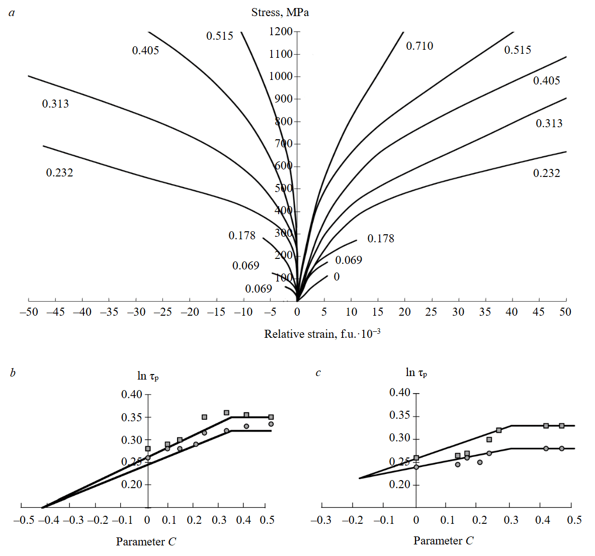
Fig.2. Diagram of marble strain under various levels of lateral pressure (a), and the dependencies of limit strength and elastic limits on parameter C for marble sample N 1 (b) and marble sample N 2 (c)
The experimental dependencies show that the studied rocks exhibited deviations from Hooke’s law during strain. The largest deviations were observed in samples of two varieties of white marble with identical mineral composition (marble N 1 and marble N 2). The results of processing expe-rimental studies on marble samples are presented in Fig.3. Analysis of the experimental results allowed determining principal relative elastic strains ε1e, ε2e=ε3e, inelastic strains ε1p=ε1-ε1e, ε2p=ε2-ε2e, as well as total θ=ε1+2ε2, elastic θe=ε1e+2ε2e, and inelastic θp=ε1p+2ε2p=θ-θe volume change.
The coefficient of inelastic lateral strain is determined by the formula
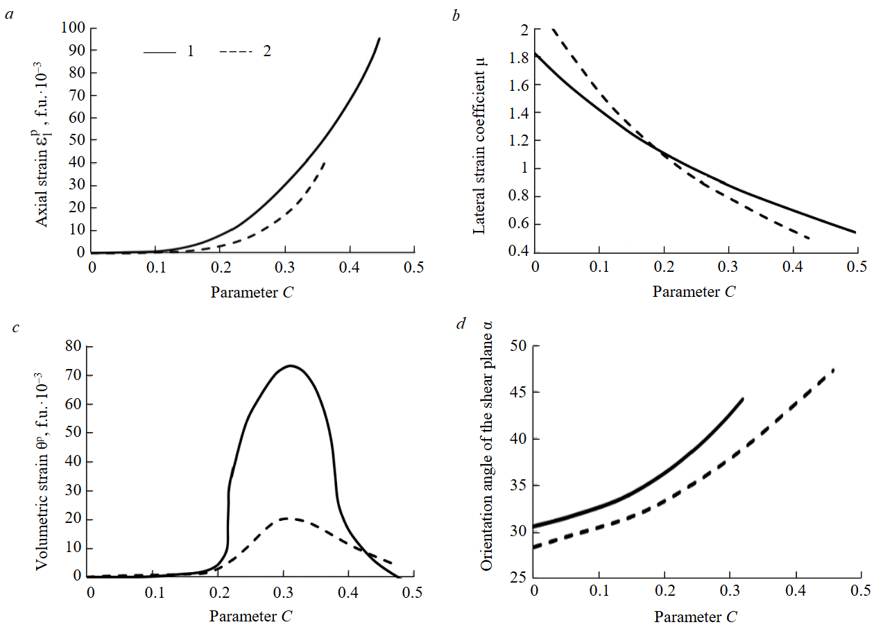
Fig.3. Dependencies of residual strains ε1p(a); lateral strain coefficient μ (b) (the angle is measured from the direction of axial stresses); volumetric strains (c), and shear plane orientation angle α (d) on parameter C for marble sample N 1 (1) and marble sample N 2 (2)
In the studied rocks, the dependence of θ on σ shows deviations of the curves (at different C values) from the hydrostatic compression line. This indicates the formation of microcracks in the tested samples. The strains were divided into elastic and residual using the method described above. Subsequently, dependencies between residual strains and the stress state parameter C were constructed.
The values of the ultimate residual volume change θp at the failure stress level, as a function of parameter C, are presented in Fig.2. Similar dependencies were obtained for other tested rocks. For all tested rocks, a characteristic feature is the presence of a maximum in volume change, the location of which along the C axis depends on the specific rock properties. For marble N 1, the value of θp at the maximum was the highest among all tested rocks. The coefficient of lateral residual strain μ, at C values close to zero, reaches its highest value in all cases – and for some rocks it exceeds 2. As C increases, the value of μ gradually decreases and tends to 0.5. When μ = 0.5, the residual volume change equals zero. A similar dependence is observed for the other investigated rocks.
At C values where μ → 0.5 and θp → 0, the shear angle tends to 45°. Under uniaxial compression, α is significantly less than 45°. Although individual data points are scattered, the overall dependence of α on C is clearly observable in all cases. The absolute values of limit strain ε1p increase, indicating a rise in the material’s plasticity.
The experimental results obtained cannot be explained by assuming that the nature of residual strains in rocks consists solely of shear processes. Evidence against this approach includes: an increase in θp and values of the coefficient μ far exceeding 0.5. The deviation of the shear angle α from 45° is only formally explained in Mohr’s theory, without revealing its physical essence.
The listed experimental results can be explained based on a simplified hypothetical scheme of the strain and failure process in an isotropic material with heterogeneous structure. When a sample deformed by principal stresses σ1 and σ2 fails, two features form: a macroscopic shear plane inclined to the sample axis at an angle α and tensile microcracks that develop along planes normal to the principal stresses. The formation of negative dilatancy (loosening) is associated with the development of tensile microcracks. The decrease in dilatancy with increasing C as μ → 0.5 is explained by the closure of tensile microcracks.
Along with strain-induced dilatancy, which is associated with strain and failure processes during stress relief, the initial effective porosity of rocks also influences dilatancy. Analysis of experimental data on dilatancy changes in marble N 1 shows that dilatancy reaches a maximum at C = 0.313 and is negative – i.e., rock loosening occurs. When C varies from 0 to 0.313, dilatancy increases; in the range from 0.313 to 0.5, dilatancy decreases to zero.
Experimental data for various rock types show that plastic dilatancy depends on C and is a nonlinear function:
Considering the relationship between C and the stresses σ and τ, the dilatancy condition can be written as:
Experimental data show that rock dilatancy is proportional to the maximum shear strain γmax=ε1p-ε3p and can be described by the following relationship:
where λ(C) is a known function determined from experimental data.
For some rock types, the experimental dependence is close to linear (Fig.4). For such rocks, the generalized expression for dilatancy can be written as
where d, d1 are the constants of linear interpolation for the dependence of plastic dilatancy on the maximum shear.
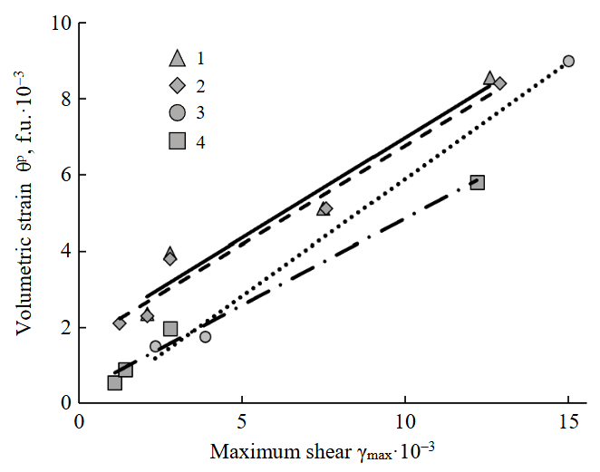
Fig.4. Linear approximation of experimental dependencies of dilatancy on maximum shear
1 – marble N 1; 2 – marble N 2; 3 – siltstone; 4 – quartz diorite
Let us consider the issues of using Stavrogin’s criterion to solve applied problems. Based on the presented theoretical provisions for predicting limit state zones in the rock mass around a mine working and displacements of the rock contour, we propose an algorithm for modelling them using the derived analytical formulas that consider Stavrogin’s criterion (see Table) in relation to a test problem. It is necessary to estimate the dimensions of the limit state zone, radial displacements of the contour of an unsupported circular mine working with the following parameters: excavation radius r0 = 5 m (see Fig.1); depth H = 1000 m from the ground surface; rock mass with the following physical and mechanical properties γ = 25 kN/m3; E0 = 1000 MPa; ν = 0.3; τp0= 8 MPa; A = 5. The problem is solved for lateral pressure coefficients in the rock mass of 0.6, 0.8, and 1.0. Additionally, the following variants are considered: a rock mass that is not subject to dilatancy during plastic strain; a dilating rock mass with parameters d = –0.268 and d1 = 0.615. The stress state is specified through the horizontal σx and vertical σy components.
Algorithm for predicting the stress-strain state of a rock mass around a mine working
|
Name of the modelling |
Scope of the modelling stage |
|
Stage 1. Obtaining initial data
|
• Weighted average specific weight of rocks γ. • Depth of working placement H. • Strength parameters of A.N.Stavrogin’s criterion τp0 and A. • Radius of the mine working in excavation R0. • Lateral pressure coefficient λ. • Strain modulus E0. • Lateral strain coefficient ν. • Support resistance at the mine working contour p0. • Linear approximation coefficients of rock dilatancy d and d1. |
|
Stage 2. Modelling of the limit state zone around the mine working
|
• Modelled: and where if the working is not supported (p0 = 0), then τ1 = τp0; • Constructing the limit state zone around a mine working (for 0 ≤ θ ≤ 2π) using the formula |
|
Stage 3. Modelling of displacements of the mine working contour |
• Modelled: • Constructing a diagram of radial displacements along the mine working contour (for 0 ≤ θ ≤ 2π) using the formula where |
The results of modelling the limit state zone around the mine working are presented in Fig.5. Based on the equations used in the modelling, it follows that dilatancy parameters – within the hypotheses embedded in the analytical methodology – do not affect the size of the limit state zone. Therefore, only the influence of the lateral pressure coefficient on this size was examined. For convenience of analysis, the linear dimensions of the limit state zone are presented in the graphical dependencies as fractions of the working radius.
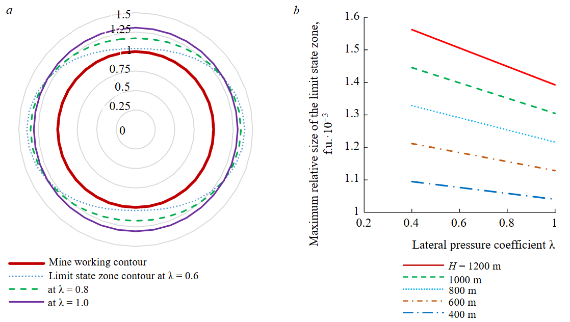
Fig.5. Limit state zone in the vicinity of a mine working: patterns of contour changes (a) and maximum linear size (b)
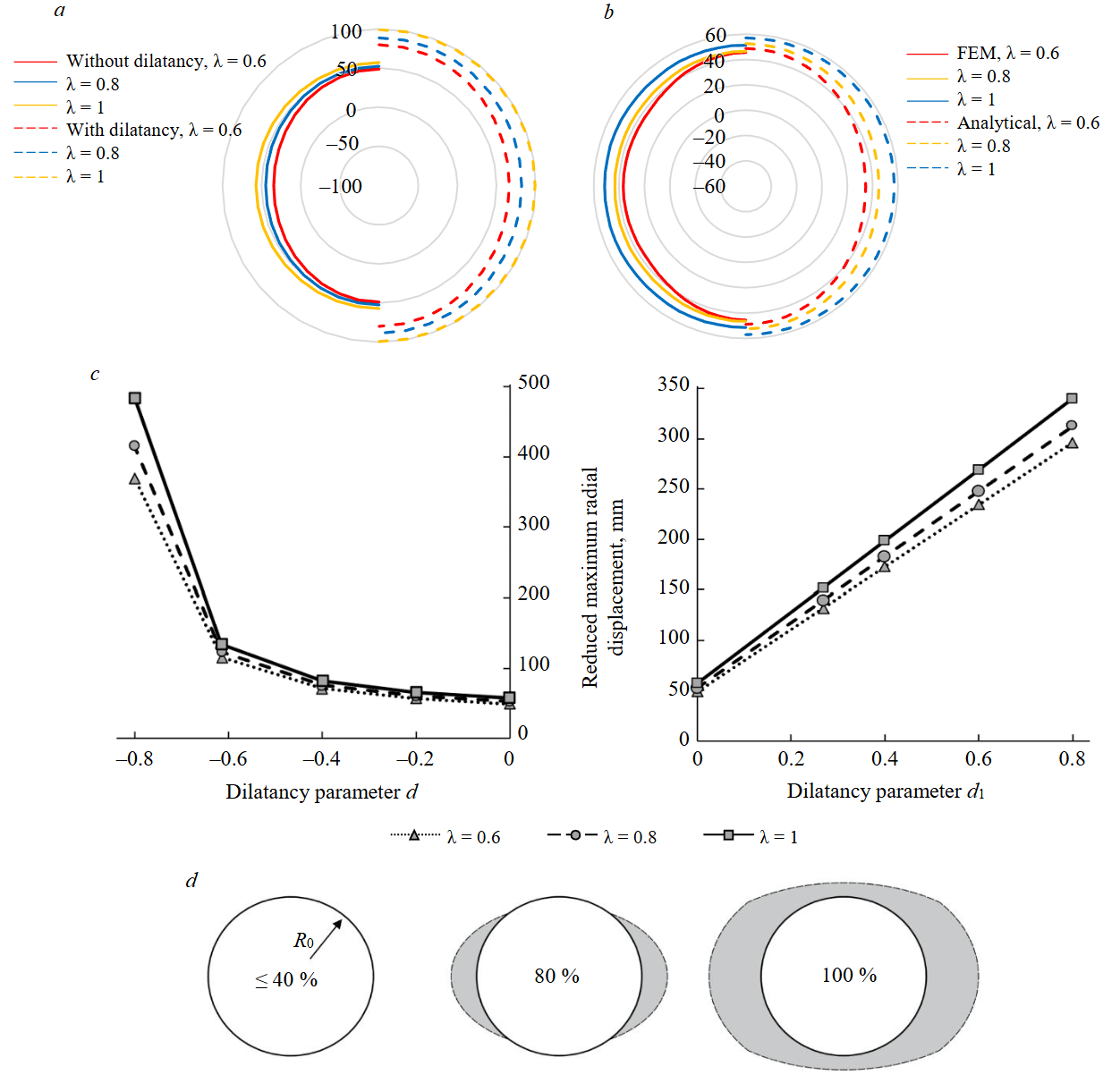
Fig.6. Results of forecasting the stress-strain state of the rock mass: a – distribution of radial displacements along the contour; b – comparison of diagrams of radial displacements of the working contour without considering the dilatancy of rocks, obtained by analytical and numerical methods; c – patterns of radial displacement variation depending on dilatancy parameters; d – formation of a limit state zone around a mine working, the numbers show the percentage of the stress-strain state redistribution in the vicinity of the mine working (0 – outside the influence zone of the working; 100 % – at infinity from the working face)
The largest dimension of the limit state zone under a gravity field of natural stresses is oriented horizontally: the lower the value of the lateral pressure coefficient λ, the more elongated the zone becomes in this direction. Analysis of the performed computations shows that full envelopment of the mine working by the limit state zone is achieved only at lateral pressure coefficients of at least 0.6. This fact limits the applicability range of the analytical methodology.
The analytical methodology presented in this work is characterized by a linear inverse dependence of the maximum linear dimension of the limit state zone on the lateral pressure coefficient and on the mine working depth. This dependence is confirmed by the results presented in Fig.5, b.
The results of modelling displacements of the mine working contour, both without and with accounting for rock dilatancy, are presented in Fig.6, a, b. For convenience of result analysis, the displacement values in the graphs are normalized to the radius of the mine working. Under conditions of a gravity stress field, the greatest radial displacement values occur at the crown of the mine working when the lateral pressure coefficients differ from unity. Accounting for dilatancy in the forecast of radial displacements leads to a significant increase in their magnitude; however, the relationships with the dilatancy parameters d and d1 are not identical. Analysis shows that the modelled value of radial displacements of the contour is nonlinearly inversely proportional to the parameter d and linearly directly proportional to the parameter d1.
Implementing A.N.Stavrogin’s strength criterion within numerical modelling allows significantly expanding the range of solvable problems in geomechanics and mechanics of underground structures. Figure 6, c illustrates the process of forming a zone of limit state around the mine working. Due to the iterative nature of computations when obtaining a numerical solution, each image corresponds to a specific portion of the total stresses implemented in the model.
At the initial stages of solving the problem, with small changes in the stress‑strain state of the rock mass, the zone of limit state has an open shape (Fig.6, d), i.e., it does not fully encompass the entire working contour. Such a pattern cannot be obtained using the analytical solution discussed earlier. Consequently, the numerical solution has a broader range of applicability and can be used for forecasting tasks in low-stress or high-strength rock masses, as well as in conditions with low lateral pressure coefficients λ < 0.6.
Let us compare the results of modelling radial displacements obtained using the analytical method and the finite element method. For clarity, the diagrams of displacement of the mine working contour, obtained when solving the problem without accounting for rock dilatancy, are superimposed in Fig.6, b, c. If we compare the forecasted radial displacements by their extreme values, the discrepancy between the forecast data ranges from 3 to 11 %. On average, along the perimeter of the mine working contour, the discrepancy falls within the 6-7 % range. Given the assumptions adopted when deriving the equations for the analytical solution and the simplifications embedded in transforming A.N.Stavrogin’s nonlinear strength condition into a piecewise-linear function within the user subroutine for numerical solution, this result can be considered acceptable, and the convergence of the two solutions can be deemed satisfactory.
It is important to note that within the framework of the numerical solution, it was not possible to account for plastic dilatancy of rocks, since the adopted rock strain model does not allow reproducing phenomena characteristic of a rock mass. Consequently, the model should be improved by modifying the plastic potential function depending on the achieved values of shear and volumetric strains.
Conclusion
The improvement of methods for solving problems in geomechanics and mechanics of underground structures aims to enhance forecast reliability through the gradual complication of applied models and approaches. This is achieved by systematically abandoning certain assumptions and simplifications. The fact of a nonlinear relationship between average stresses and rock strength was found long ago, but its implementation in practical problems has become feasible only recently due to significant advancements in the computational capabilities of numerical methods. Implementing A.N.Stavrogin’s strength criterion in numerical modelling enables obtaining solutions for predicting displacements of mine working’s contours and sizes of limit state zones in their vicinity, which are comparable in accuracy to analytical solutions. Such solutions do not have significant limitations in terms of applicability that are typical for analytical solutions and stem from initial premises embedded in the derivation of equations. Furthermore, the finite element method allows solving problems within a spatial formulation, which is unattainable using analytical methods.
During the present work, we identified the necessity to refine the rock strain model into a form that fully accounts for the features of volumetric strain under plastic shear. This research direction constitutes a natural continuation of the work.
References
- Basalaeva P.V., Kuranov A.D. Influence of dip angle of lithologically nonuniform interburden on horizontal mine opening stability during driving. Mining Informational and Analytical Bulletin. 2024. N 3, p. 17-30 (in Russian). DOI: 10.25018/0236_1493_2024_3_0_17
- Belikov A.A., Belyakov N.A. Method of predicting the stress-strain state of interchamber pillars lined with a compliant rope fastener. Mining Informational and Analytical Bulletin. 2023. N 4, p. 20-34 (in Russian). DOI: 10.25018/0236_1493_2023_4_0_20
- Demenkov P.A., Romanova Е.L., Kotikov D.A. Stress–strain analysis of vertical shaft lining and adjacent rock mass under conditions of irregular contour. Mining Informational and Analytical Bulletin. 2023. N 11, p. 33-48 (in Russian). DOI: 10.25018/0236_1493_2023_11_0_33
- Protosenya A.G., Karasev M.A., Belyakov N.A. Elastoplastic problem for noncircular openings under Coulomb’s criterion. Journal of Mining Science. 2016. Vol. 52. N 1, p. 53-61. DOI: 10.1134/S1062739116010125
- Gospodarikov A.P., Zatsepin M.A. Mathematical modeling of boundary problems in geomechanics. Gornyi zhurnal. 2019. N 12, p. 16-20 (in Russian). DOI: 10.17580/gzh.2019.12.03
- Ilinov M.D., Korshunov V.A., Pospekhov G.B., Shokov A.N. Integrated experimental research of mechanical properties of rocks: Problems and solutions. Gornyi zhurnal. 2023. N 5, p. 11-18 (in Russian). DOI: 10.17580/gzh.2023.05.02
- Gospodarikov A.P., Kirkin A.P., Trofimov A.V., Kovalevsky V.N. Determination of physical and mechanical properties of rocks using anti-burst destress measures. Gornyi zhurnal. 2023. N 1, p. 26-34 (in Russian). DOI: 10.17580/gzh.2023.01.04
- Korshunov V.A., Pavlovich A.A., Bazhukov A.A. Evaluation of the shear strength of rocks by cracks based on the results of testing samples with spherical indentors. Journal of Mining Institute. 2023.Vol. 262, p. 606-618. DOI: 10.31897/PMI.2023.16
- Verbilo P.E., Vilner M.A. Study of the jointed rock mass uniaxial compression strength anisotropy and scale effect. Mining Informational and Analytical Bulletin. 2022. N 6-2, p. 47-59 (in Russian). DOI: 10.25018/0236_1493_2022_62_0_47
- Ilyinov M.D., Petrov D.N., Karmanskiy D.A., Selikhov A.A. Physical simulation aspects of structural changes in rock samples under thermobaric conditions at great depths. Mining Science and Technology. 2023. Vol. 8. N 4, p. 290-302. DOI: 10.17073/2500-0632-2023-09-150
- Schwartzkopff A.K., Sainoki A., Bruning T., Karakus M. A conceptual three-dimensional frictional model to predict the effect of the intermediate principal stress based on the Mohr-Coulomb and Hoek-Brown failure criteria. International Journal of Rock Mechanics and Mining Sciences. 2023. Vol. 172. N 105605. DOI: 10.1016/j.ijrmms.2023.105605
- Naiyu Liu, Puhui Chen. A failure envelope proposal based on the analysis of the requirements of nonlinear Mohr-Coulomb criteria. Mechanics Research Communications. 2023. Vol. 129. N 104086. DOI: 10.1016/j.mechrescom.2023.104086
- Jianbin Tang, Xi Chen, Liusheng Cui, Zongqi Liu. Strain localization of Mohr-Coulomb soils with non-associated plasticity based on micropolar continuum theory. Journal of Rock Mechanics and Geotechnical Engineering. 2023. Vol. 15. Iss. 12, p. 3316-3327. DOI: 10.1016/j.jrmge.2023.02.029
- Trushko V.L., Baeva E.K. Substantiation of rational parameters of mine support system for underground roadways in difficult geological conditions. Mining Informational and Analytical Bulletin. 2023. N 12, p. 55-69 (in Russian). DOI: 10.25018/0236_1493_2023_12_0_55
- Pin-Qiang Mo, Hai-Sui Yu. Plasticity Solutions of an Undrained Cavity Contraction for the Prediction of Soil Behaviour around Tunnels. Fourth Geo-China International Conference, 25-27 July 2016, Shandong, China. American Society of Civil Engineers, 2016, p. 150-157. DOI: 10.1061/9780784480038.019
- Yu-Lin Lee, Chih-Sheng Chen, Tseng-Hsing Hsu, Chi-Min Lee. Explicit Analysis for the Ground Reaction of a Circular Tunnel Excavated in Anisotropic Stress Fields based on Hoek–Brown Failure Criterion. Mathematics. 2024. Vol. 12. Iss. 17. N 2689. DOI: 10.3390/math12172689
- Kai Guan, Quanyun Zhang, Honglei Liu, Wancheng Zhu. A New Numerical Procedure for the Excavation Response in Mohr–Coulomb Rock Mass Exhibiting Strain-Softening Behavior. Frontiers in Earth Science. 2022. Vol. 10. N 872792. DOI: 10.3389/feart.2022.872792
- Yong Li, Shugang Cao, Nicholas Fantuzzi, Yanbao Liu. Elasto-plastic analysis of a circular borehole in elastic-strain softening coal seams. International Journal of Rock Mechanics and Mining Sciences. 2015. Vol. 80, p. 316-324. DOI: 10.1016/j.ijrmms.2015.10.002
- Jin-feng Zou, Shuai-shuai Li, Yuan Xu et al. Theoretical solutions for a circular opening in an elastic–brittle–plastic rock mass incorporating the out-of-plane stress and seepage force. KSCE Journal of Civil Engineering. 2016. Vol. 20. Iss. 2, p. 687-701. DOI: 10.1007/s12205-015-0789-y
- Yuming Sheng, Peng Li, Shutong Yang, Jinfeng Zou. Elastoplastic solutions for deep-buried twin tunnels with arbitrary shapes and various arrangements under biaxial in-situ stress field based on Mohr-Coulomb and generalized Hoek-Brown criteria. Computers and Geotechnics. 2024. Vol. 165. N 105896. DOI: 10.1016/j.compgeo.2023.105896
- Tianzheng Li, Wenping Gong, Xiaoli Yang. Stability analysis of a non-circular tunnel face in soils characterized by modified Mohr-Coulomb yield criterion. Tunnelling and Underground Space Technology. 2021. Vol. 109. N 103785. DOI: 10.1016/j.tust.2020.103785
- Yuming Sheng, Jinfeng Zou, Yuepeng Dong, Guang-Hui Chen. Novel perturbation solutions for deep-buried non-circular tunnels under biaxial in situ stress field based on Mohr-Coulomb criterion. Applied Mathematical Modelling. 2022. Vol. 110, p. 408-440. DOI: 10.1016/j.apm.2022.06.006
- Zenghui Zhao, Wei Sun, Shaojie Chen et al. Displacement of surrounding rock in a deep circular hole considering double moduli and strength-stiffness degradation. Applied Mathematics and Mechanics. 2020. Vol. 41. Iss. 12, p. 1847-1860. DOI: 10.1007/s10483-020-2665-9
- Hongying Wang, Qiang Zhang, Peinan Wu et al. Elastoplastic solution of a circular tunnel in surrounding rock with any nonlinear yield criteria and plastic flow envelopes. Computers and Geotechnics. 2024. Vol. 166. N 105954. DOI: 10.1016/j.compgeo.2023.105954
- Yiouta-Mitra P., Sakurai S. Critical strain method incorporating calculation of equivalent H-B strength parameters for back analysis during tunnel excavation. Tunnelling and Underground Space Technology. 2023. Vol. 140. N 105252. DOI: 10.1016/j.tust.2023.105252
- Baotang Shen, Jingyu Shi, Barton N. An approximate nonlinear modified Mohr-Coulomb shear strength criterion with critical state for intact rocks. Journal of Rock Mechanics and Geotechnical Engineering. 2018. Vol. 10. Iss. 4, p. 645-652. DOI: 10.1016/j.jrmge.2018.04.002
- Pei-Zhi Zhuang, Hai-Sui Yu. Two-dimensional elastoplastic analysis of cylindrical cavity problems in Tresca materials. International Journal for Numerical and Analytical Methods in Geomechanics. 2019. Vol. 43. Iss. 8, p. 1612-1633. DOI: 10.1002/nag.2925
- Xiongfei Yang, Hong Yuan, Jiayu Wu, Shanqing Li. Elastoplastic Analysis of Circular Tunnel Based on Drucker–Prager Criterion. Advances in Civil Engineering. 2018. Vol. 2018. N 5149789. DOI: 10.1155/2018/5149789
- Zareifard M.R. Ground response curve of deep circular tunnel in rock mass exhibiting Hoek–Brown strain-softening behaviour considering the dead weight loading. European Journal of Environmental and Civil Engineering. 2021. Vol. 25. Iss. 14, p. 2509-2539. DOI: 10.1080/19648189.2019.1632745
- Pijush Pal Roy, S. Rama Raju, Dipankar Chattopadhyay. An Overview of Tunnel Support Systems under Squeezing Rock Condition in Arun Hydroelectric Project, Stage-III, Eastern Nepal. SSRN. 2023, p. 15. DOI: 10.2139/ssrn.4461004
- Chen Xu, Sheng Wang, Caichu Xia. Analytical prediction for time-dependent interaction of a circular tunnel excavated in strain-softening rock mass. Rock Mechanics Bulletin. 2024. Vol. 3. Iss. 3. N 100127. DOI: 10.1016/j.rockmb.2024.100127
- Vrakas A., Anagnostou G. A finite strain closed-form solution for the elastoplastic ground response curve in tunneling. International Journal for Numerical and Analytical Methods in Geomechanics. 2014. Vol. 38. Iss. 11, p. 1131-1148. DOI: 10.1002/nag.2250
- Vrakas A., Anagnostou G. Finite strain elastoplastic solutions for the undrained ground response curve in tunneling. International Journal for Numerical and Analytical Methods in Geomechanics. 2015. Vol. 39. Iss. 7, p. 738-761. DOI: 10.1002/nag.2335
- Galindo R.A., Serrano A., Olalla C. Ultimate bearing capacity of rock masses based on modified Mohr-Coulomb strength criterion. International Journal of Rock Mechanics and Mining Sciences. 2017. Vol. 93, p. 215-225. DOI: 10.1016/j.ijrmms.2016.12.017
- Arora K., Gutierrez M. Viscous-elastic-plastic response of tunnels in squeezing ground conditions: Analytical modeling and experimental validation. International Journal of Rock Mechanics and Mining Sciences. 2021. Vol. 146. N 104888. DOI: 10.1016/j.ijrmms.2021.104888
- Yaocai Ma, Aizhong Lu, Hui Cai, Xiangtai Zeng. A semi-analytical method for elastic-plastic analysis of a deep-buried elliptical tunnel. Computers and Geotechnics. 2022. Vol. 142. N 104589. DOI: 10.1016/j.compgeo.2021.104589
- Yaocai Ma, Aizhong Lu, Hui Cai, Xiangtai Zeng. Analytical solution for determining the plastic zones around two unequal circular tunnels. Tunnelling and Underground Space Technology. 2022. Vol. 120. N 104267. DOI: 10.1016/j.tust.2021.104267