Monitoring of grinding condition in drum mills based on resulting shaft torque

Abstract
Grinding is the most energy-intensive process among all stages of raw material preparation and determines the course of subsequent ore beneficiation stages. Level of electricity consumption is determined in accordance with load characteristics forming as a result of ore destruction in the mill. Mill drum speed is one of process variables due to which it is possible to control ore destruction mechanisms when choosing speed operation mode of adjustable electric mill drive. This study on increasing energy efficiency due to using mill electric drive is based on integrated modelling of process equipment – grinding process and electromechanic equipment – electric drive of grinding process. Evaluating load torque by means of its decomposition into a spectrum, mill condition is identified by changing signs of frequency components of torque spectrum; and when studying electromagnetic torque of electric drive, grinding process is monitored. Evaluation and selection of efficient operation mode of electric drive is based on the obtained spectrum of electromagnetic torque. Research results showed that with increasing mill drum speed – increasing impact energy, load torque values are comparable for the assigned simulation parameters. From the spectra obtained, it is possible to identify mill load condition – speed and fill level. This approach allows evaluating the impact of changes in process variables of grinding process on parameters of electromechanical system. Changing speed operation mode will increase grinding productivity by reducing the time of ore grinding and will not lead to growth of energy consumption. Integration of digital models of the technological process and automated electric drive system allows forming the basis for developing integrated methods of monitoring and evaluation of energy efficiency of the entire technological chain of ore beneficiation.
None
Introduction
Grinding process is the most energy-intensive process in preparation of raw materials at mining and processing enterprises. In accordance with sustainable development trends [1, 2], which have a significant impact on industrial facilities due to the established resource saving policy, it is necessary to consider the means to increase the efficiency of the grinding process [3, 4].
There are the following possibilities of increasing the grinding process efficiency [5]: improvement of design solutions; use of advanced process control systems (APC); diagnostics of grinding process and assessment of residual resource; process engineering solutions for increasing energy efficiency; electromechanical solutions.
Design solutions
Drum mills are the most widespread grinding units characterized by high energy intensity as compared with other types of equipment for raw material disintegration.
Development of ore preparation schemes with gravity vertical mills and roller presses is important [6]. Specific energy consumption of this equipment per 1 ton of product is on average 25 % less than that of drum mills. The researchers emphasize the importance of optimizing geometric parameters of drum mill lifters to reduce energy consumption [7]. Lately, the use of DEM-modelling became widespread for solving many technological problems of grinding process.
Discrete element method (DEM) is designed to calculate the behaviour of granular media and is based on calculation of contact interactions between conditionally indivisible granular particles [8, 9]. DEM method replaced the classical theories of calculating energy consumption. In the classical theory, calculation of energy consumption is based on the main empirical formulas: those of Olevsky, Chen Bingchen, Davis, Levinson, Bond [10]. However, almost all classical methods do not consider the effect of lifters and only reflect the effect of rotation speed, degree of charge fill, size, and shape of grinding media. DEM method allows estimating power consumption based on interaction of materials involved in grinding process.
In [11], DEM model was validated with experimental data; it was found that the model is correct when developing the design of mill lifters. In [12], it was noted that when choosing a suitable combination of design parameters of lifters and process variables (speed and mill fill), energy efficiency of the grinding process increases. Selection of such a combination for full-scale mills in practice is difficult, which emphasizes the relevance of DEM-modelling.
Advanced control systems
Synthesis of process control system is accomplished following the mathematical description of the control object. Chemical technological processes occur in moving streams, their movement affecting the efficiency of these processes. Use of hydrodynamic equations to describe the mechanical movement of milled product flows is a common method for designing grinding units and their control systems [13].
Classical grinding process control loops are built on the principle of stabilizing the main process variables. Feedstock consumption in the mill drum is the main parameter according to which control is performed. To maintain the assigned class –0.074 mm on control sieve, water flow in the mill and hydro cyclone is additionally controlled [14]. Higher requirements to modern mining and processing plants lead to the need of introducing optimization loops into existing control systems. Building such control systems involves integrated mathematical modelling of the processes occurring in processing units at full cycle of producing finished product [15, 16]. Thus, the task of improved control systems is not only to maintain nominal productivity of grinding process, but also to optimize it for cost reduction.
Diagnostics of grinding process and evaluation of residual resource
These methods of increasing the efficiency are aimed at reducing additional losses of consumed energy that occur during operation of faulty equipment. Timely prevention of breakdowns as they develop allows bringing down the likelihood of process equipment downtime, eliminating failure of design and electromechanical components of mill-electric drive system and reducing the numbers of scheduled preventive maintenance for replacing certain equipment elements. When diagnosing design components of the mill, dynamic state of the mill is identified, as a rule, by acoustic signals [17] and vibration [18, 19]. In accordance with the data obtained, it is possible to characterize wear condition of mill lining and lifters. It is most convenient to control condition of the main electromechanical components of mill drive by monitoring stator currents [20, 21]. The effect of process variables on electromechanical system can be seen in electric drive signals.
Electromechanical solutions
Introduction of an adjustable electric drive of mill rotation mechanism is one of the ways to increase energy efficiency of grinding process [22]. This allows controlling the dynamics of in-mill load, excluding ore zones that are not ground and increasing the efficiency of grinding process [23, 24].
As a rule, the effect of the above methods is observed in case of their integrated use, which became possible in the era of the Fourth industrial revolution [25, 26]. Introduction of cyber-physical systems in mining industry based on such key Industry 4.0 trends as the industrial Internet of things (IIoT), big data analytics, artificial intelligence and digital modelling allow to ensure the interaction of equipment throughout the production chain of finished product and adaptation of technological processes to external and internal changes [27, 28]. Such prognostic analysis allows the enterprises to predict technical condition of equipment and issue appropriate recommendations to improve the work efficiency based on operation data by studying processes in a virtual environment [29, 30].
Technological solutions
Main adjustable process variables, due to which productivity can be increased, are load level, amount of grinding media and drum mill rotation speed [31]. Design features of lifters also affect the behaviour of load inside the mill. If the dynamics of in-mill load is not controlled, most of energy is not spent on grinding ore, but on destruction of grinding media and damage to lining and other mechanical components of mill [23].
Several researchers from specialized institutes studying grinding process presume that mill speed should be changed during grinding process. The main factor requiring a change in mill speed mode is variability of physicomechanical properties of ore in the course of deposit development [32].
As a rule, controllable electric drives of SAG mills are used to start them. However, not at all factories frequency converters ensure only soft start. For example, at Copper Mountain factories, electrically controlled mills did not rotate at constant speed during two months of operation, but the speed ranged between 7 and 10 rpm. Speed variation in this range covers all operation modes of mills.
Mill load or fill level is the main parameter, as it determines technological stability of grinding process. Incorrect identification of this parameter can lead not only to a decrease in productivity (if its value is reduced), but also to a disruption in operation of the technological system, damage to mill components (if its value is increased).
The main difficulty in studying load behaviour is impossibility to install measuring devices inside mill housing. In this case, only indirect monitoring methods are realized [22, 24].
There are diverse ways to obtain information about the processes taking place in the mill. Monitoring of acoustic emissions and vibrations became widespread when determining the fill of mills [33, 34]. However, these methods of determining current fill of mill have significant inaccuracies due to interference of mechanisms [35, 36]. Main disadvantage of the methods for monitoring mill load level at certain frequencies is the influence of natural frequency components of mechanical parts of mills [37, 38].
Unlike vibro- and acoustic signals, shaft torque depends directly on changes in process variables and does not depend on natural frequency of mechanical equipment [39]. Torque signal can be obtained in an accessible way using coordinate observer due to current signals, since these meters are installed together with controlled electric drive of the mill.
The purpose of the article is to study the influence of grinding process variables on spectral components of electromagnetic torque of the motor in automated electric drive system to determine the optimal operation mode. At the optimal operation mode of electric drive, ore grinding will proceed at minimal energy consumption, ensuring nominal technological characteristics. Since it is difficult to identify mill condition (determination of fill level), it is proposed to consider spectral composition of electromagnetic torque of the motor for excluding false recommendations on choosing mill operation mode.
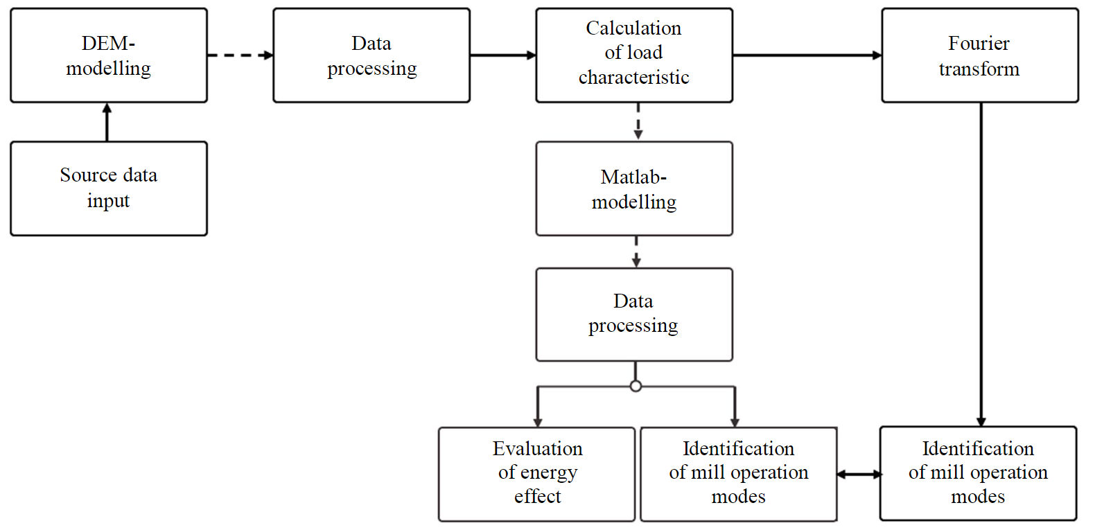
Fig.1. Methodology of research
There are several studies on mill load behaviour using torque evaluation [39, 40]. Resulting collisions between particles and pulp movement inside the mill create intense vibration in mechanical equipment, which leads to torque fluctuations on mill shaft. Fluctuations are reflected in consumed current, generated torque, and angular velocity of electric drive. Thus, torque signal is informative both from electromechanical and technological point of view.
Methodology
Study was based on integrated modelling of process and electromechanical equipment of mill-electric drive system. The methodology comprises two branches and nine main stages (Fig.1). In the first branch, the behaviour of in-mill load was investigated using DEM-modelling in Rocky DEM software. When constructing a drum mill model, it is necessary to select physical models (simulation algorithm) for calculating internal forces between particles and modelling object – mill; to set the geometry of the object; to set rotational movement of the object; to create internal volumetric mill fill.
In the second branch of research, evaluation of energy simulation is made based on simulation of mill electric drive and evaluation of electromagnetic torque in Matlab software.
Simulation algorithms
DEM-modelling algorithms are based on calculation [41] of normal and tangential components of interaction forces of pairs: particle-particle and particle-boundary of simulation object.
In accordance with linear elastic hysteresis model [42], normal component of interaction force to contact plane is calculated as follows:
where Knl and Knu are values of loading and unloading contact stiffness; Fnt and Fnt-Δt – normal elastic-plastic contact forces at current timepoint and at previous timepoint ΔSn – modelling step; – change in normal overlap of particle contacts at current timepoint (positive when particles approach each other, and negative when they move away); Snt and Snt-Δt – values of normal overlap at current and previous timepoints; λ – constant, λ = 0.001.
Elastic frictional tangential component is calculated using Linear spring Coulomb limit model [43]:
where Fnt-Δt is the value of tangential force at previous timepoint; ΔSτ – tangential relative displacement of particles during time interval; Kτ – tangential stiffness; μ – friction coefficient.
Since simulated particles inside the mill are spherical, particle rolling resistance model is used. According to model [44] “Type C: linear spring rolling limit”
where Mtr is rolling resistance torque vector; Mr,lim – limit value of rolling resistance torque; Mt-Δtr – vector of rolling resistance torque at previous timepoint; Kr – rolling stiffness; ωrel – relative angular velocity vector.
Drum mill geometry
To reduce the process simulation times, calculation or computation was made for a 0.9. m long drum mill section. In this article, a semi-autogenous grinding mill was simulated. The model presumes that all particles interacting inside the mill are spherical. Such solution allows simplifying the calculations and reducing the simulation time; however, it does not allow considering the geometry of real ground particles. A change in particle geometry is not considered as a factor influencing the behaviour of load characteristic for subsequent simulation of electric drive. However, the influence of geometry of ground particles on a change in in-mill load behaviour, speed and torque cannot be denied [45].
Geometrical parameters and process equipment of the mill set at simulation are: outer diameter of mill 11.5 m; section length 0.9 m; nominal weight of ore mo1 =30 t; nominal weight of grinding media mt = 8 t; ore density 2,800 kg/m3; density of grinding media 7,800 kg/m3.
Duration of simulation was 35 s with simulation step 0.0005 s. Drum rotation speeds were selected in accordance with recommended mode values when designing beneficiation plants. As a rule, the regulation range is within 0.5-0.85 of critical speed ncr.
Grinding process proceeds under the influence of three main mechanisms of destruction: impact, attrition, and abrasive wear. The influence of these mechanisms will be different depending on mill operation mode. Operation mode is determined by mill speed. According to [46], seven high-speed operation modes are distinguished. Operation mode is usually expressed in relation to critical speed. When critical speed value is exceeded, particles begin to centrifuge and stick to the drum under the action of centrifugal forces [47],
This operation mode is unacceptable; there is no impact of destructive forces – no ore grinding is carried out. There are three main mill operation modes:
- cascade (drum speed 50-60 % of critical speed);
- waterfall (drum speed 70-85 % of critical speed);
- mixed (intermediate between cascade and waterfall with drum rotation frequency 60-70 % of critical speed).
At lower speeds, particles roll from one part of the drum to another, destruction occurs under the action of attrition and abrasive wear. With increasing mill rotation speed upper layers of particles break away from others, rise and at top of the trajectory fall under the action of gravity. Destruction of these layers occurs under the action of impact. In practice, impact is used to break large hard particles, and attrition is used to reduce the size of less hard rock material to obtain a given size class at subsequent beneficiation stages.
Characteristic speed values were chosen corresponding to three considered mill operation modes: n1 – cascade – 65 % of ncr = 0.84 rad/s (8 rpm); n2 – waterfall – 80 % of ncr = 1.05 rad/s (10 rpm); n3 – critical – 100 % of ncr = 1.31 rad/s (12.5 rpm).
Figure 2 shows mill operation modes when simulating grinding process in Rocky DEM.
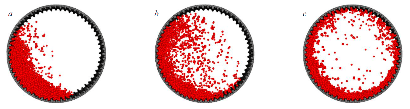
Fig.2. Mill operation modes: a – cascade; b – waterfall; c – critical
During research, the factor of changing mill load was considered. In mill model, three feedstock charges were specified: mo1 = 25 t, mo2 = 35 t and mo3 = 40 t. For each charge, grinding at three speeds n1, n2 and n3 was performed.
Useful component is extracted from pulp (during beneficiation by flotation or “coal in pulp”), therefore, in addition to ore, water is also loaded into mill. Addition of water has a significant effect on obtaining the required finished product – 0.074 mm, so its presence in mill drum should be considered [48, 49]. Addition of water was not considered, since its presence implies additional CFD- modelling, and the study focuses on implementation of electromechanical system of grinding process.
After each experiment, data were exported to Microsoft Excel. Then, the module of equivalent torque was calculated in three projections x, y and z in accordance with Rocky DEM data:
The obtained torque was used as load characteristic for electric drive model in Matlab Simulink at the second stage of research.
After fast Fourier transform operation, spectra of equivalent torque modules were obtained using which mill operation modes were identified. Thus, a matrix of drum mill condition was obtained from spectral components of load torque. Then, it is necessary to pass to the second branch of research in Matlab Simulink, so that mill condition could be determined during its operation from spectral components of electromagnetic torque.
The trend to reduce technological chains and increase throughput of grinding units is still relevant, which increases the requirements for mills in designing and operation [50]. Electric drive of grinding process is the main consumer at mining enterprise, and it should be controlled in accordance with process variables for increasing drum mill efficiency [51]. For electric drive of the grinding process, kinematic structures can be used: single-engined, double-engined, direct-driven. Transition to a double-engined structure is justified by the maximum mechanical torque that can be transmitted through gear coupling. At powers above 9 MW, torque transmission through one gear is impossible. Gearless electric drive is characterized by the highest energy efficiency since it does not contain transmission devices. It is advisable to use this electric drive within power range from 12 to 36 MW.
The most advanced motors used in electric drive are squirrel-cage induction motors (SCIM), switched reluctance motors (SRM) and synchronous motors with permanent magnets (PMSM). In view of high manufacturing cost of PMSM, it is advisable to consider and develop ways to increase the efficiency of asynchronous and switched reluctance electric drives used to control grinding process [52, 53].
Electric drives of mill units are characterized by heavy-duty operation. Technological
features of grinding process complicate the operation of electric drives. Electric drive selected on the basis of calculation methods for nominal operating mode of the mill may not generate a starting torque if ore solidifies. In this case, power of the machine will be overestimated, and when nominal operation mode is reached, energy indicators of efficiency and power factor will have lower values.
Mills operate in a continuous mode; their operation is suspended only for the period of scheduled preventive maintenance to replace the lining and other components once a month. The article investigates the operation of asynchronous electric drive of grinding process, which runs under load when a steady state operation mode of the mill unit is reached.
Figure 3 shows a simulation model of mill electric drive. Drum mills are powered by 6/10 kV voltage. At mining and processing plants with low and medium output of finished products, capacity of ball mills is 1 MW. To simulate the electric drive, an induction motor was taken with the following parameters: power 1 MW, supply voltage 6 kV, rated speed 595 rpm, cosφ = 0.85, efficiency = 0.972, overload capacity 4.5. Winding parameters of the motor are calculated using method of I.P.Kopylov.
As a result of simulation modelling, the function of electromagnetic torque was decomposed into spectral components using Fourier transform. Based on these components, mill operation modes were identified and compared with load torque spectrum obtained in the first part
of research.
In data processing, it is necessary to take energy and load characteristics from which energy effect is evaluated and mill operation modes are identified. In this study, evaluation of energy performance and energy efficiency criteria was not accomplished.
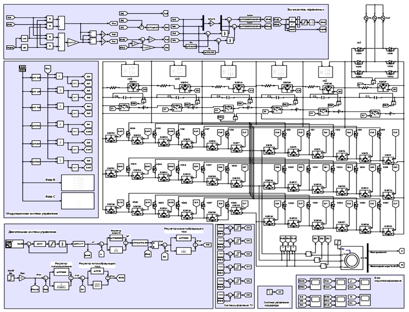
Fig.3. Simulation model of grinding process electric drive
To reduce simulation time, a time interval was taken corresponding to mill reaching steady state operation mode. Such mode is achieved if average coordinates of all particles along vertical and horizontal axes reach conditionally unchangeable values [53]. Steady state operation mode is attained at time moment 16 s. Thus, load interval was chosen corresponding to 2 s of load characteristic time at load 35 t and speed 1.05 rad/s from 16 to 18 s.
Simulation of asynchronous electric drive was performed with simulation step 0.000002 s. This step is chosen in accordance with carrier signal frequency of modulation control system of an inverter.
Discussion of results
Results of experiments are shown in Fig.4, 5. The greater the mill speed, the more the torque takes the form of a periodic signal (Fig.4). At speed 1.31 rad/s, load begins to centrifuge, and load torque decreases. In accordance with cascade mill operation mode 0.84 rad/s, ore will be ground to a finer fraction. When ore is destroyed by an impact of 1.05 rad/s, high power is required, but studies showed that cascade and waterfall modes can be comparable in power. Changing speed during mill operation will have almost no effect on consumed electric energy but will increase grinding performance by reducing ore grinding time.
For each mill condition, it is possible to obtain a characteristic set of frequency components of torque spectrum (FCMS) of a certain amplitude (Fig.5, Table 1). Let us presume that it is possible to track mill load level at a certain speed by changing signs of frequency components of the spectrum (Table 2). However, this requires continuous monitoring of torque signal and comparison of spectral components with each other.
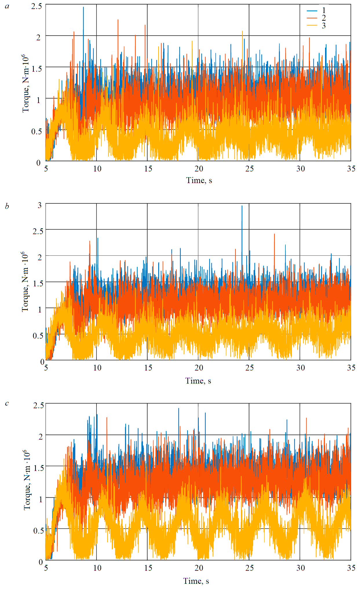
Fig.4. Module of equivalent mill torque at load 25 t (a), 35 t (b) and 40 t (c) at speed 0.84 rad/s (1), 1.05 rad/s (2) and 1.31 rad/s (3)
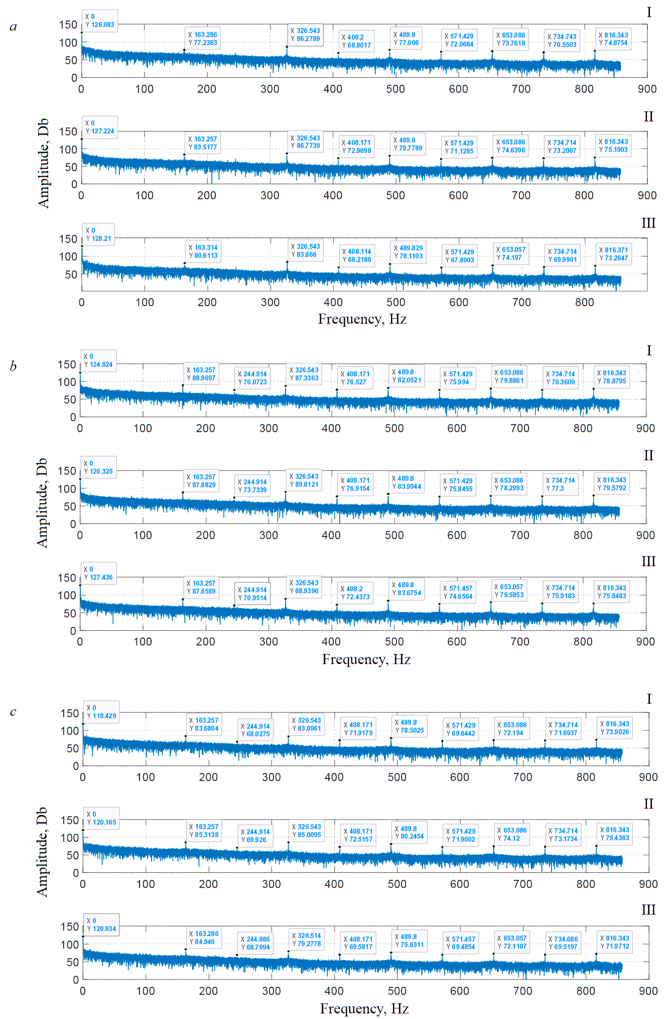
Fig.5. Spectra of load torques at load 25 t (I), 35 t (II), 40 t (III) and speed 0.84 rad/s (a), 1.05 rad/s (b) and 1.31 rad/s (c)
Tabe 1
Mill condition matrix
|
Speed, rad/s (rpm) |
Load, t |
1 FCMS |
2 FCMS |
3 FCMS |
4 FCMS |
5 FCMS |
6 FCMS |
7 FCMS |
8 FCMS |
9 FCMS |
10 FCMS |
||||||||||
|
ƒ1, Hz |
М1, Db |
ƒ2, Hz |
М2, Db |
ƒ3, Hz |
М3, Db |
ƒ4, Hz |
М4, Db |
ƒ5, Hz |
М5, Db |
ƒ6, Hz |
М6, Db |
ƒ7, Hz |
М7, Db |
ƒ8, Hz |
М8, Db |
ƒ9, Hz |
М9, Db |
ƒ10, Hz |
М10, Db |
||
|
0,84 (8) |
25 35 40 |
0 0 0 |
126,1 127,2 128,2 |
163,3 163,3 163,3 |
77,2 83,5 80,6 |
244,9 244,9 244,9 |
68,7 70,5 68,6 |
326,5 326,5 326,5 |
86,3 86,8 83,9 |
408,2 408,2 408,2 |
68,8 72,9 68,2 |
489,8 489,8 489,8 |
77,6 79,8 78,1 |
571,4 571,4 57I,4 |
72,1 71,1 67,9 |
653,1 653,1 653,1 |
73,8 74,6 74,2 |
734,7 734,7 734,7 |
70,7 73,2 70,0 |
816,3 816,3 816,4 |
74,9 75,2 73,3 |
|
1,05(10) |
25 35 40 |
0 0 0 |
124,9 126,3 127,4 |
163,3 163,3 163,3 |
89,0 87,9 87,7 |
244,9 244,9 244,9 |
76,1 73,7 71,0 |
326,5 326,5 326,5 |
87,3 89,8 88,9 |
408,2 408,2 408,2 |
76,5 76,9 72,4 |
489,8 489,8 489,8 |
82,5 84,0 83,7 |
571,4 571,4 571,4 |
76,0 75,9 74,7 |
653,1 653,1 653,1 |
80,0 78,3 79,6 |
734,7 734,7 734,7 |
76,3 77,3 75,9 |
816,3 816,3 816,3 |
78,9 79,6 75,9 |
|
1,31(12,5) |
25 35 40 |
0 0 0 |
118,4 120,2 120,9 |
163,3 163,3 153,3 |
83,7 85,3 85,0 |
244,9 244,9 244,9 |
68,0 69,9 68,8 |
326,5 326,5 326,5 |
83,1 85,0 79,3 |
408,2 408,2 408,2 |
71,9 72,5 69,6 |
489 489,9 489,9 |
78,5 80,2 75,6 |
571,4 571,4 571,4 |
69,6 72,0 69,5 |
653,1 653,1 653,1 |
72,2 74,1 72,1 |
734,7 734,7 734,7 |
71,7 73,2 69,5 |
816,3 816,3 816,3 |
73,9 75,4 72,0 |
Table 2
In-mill load identification
|
Speed, rad/s (rpm) |
Load, t
|
1 FCMS |
2 FCMS |
3 FCMS |
4 FCMS |
5 FCMS |
6 FCMS |
7 FCMS |
8 FCMS |
9 FCMS |
10 FCMS |
||||||||||
|
ƒ1, Hz |
М1, Db |
ƒ2, Hz |
М2, Db |
ƒ3, Hz |
М3, Db |
ƒ4, Hz |
М4, Db |
ƒ5, Hz |
М5, Db |
ƒ6, Hz |
М6, Db |
ƒ7, Hz |
М7, Db |
ƒ8, Hz |
М8, Db |
ƒ9, Hz |
М9, Db |
ƒ10, Hz |
М10, Db |
||
|
0,84 (8) |
25 35 |
0 0 |
↑ |
163,3 163,3 |
↑ |
244,9 244,9 |
↑ |
326,5 326,5 |
↑ |
408,2 408,2 |
↑ |
489,8 489,8 |
↑ |
571,4 571,4 |
↓ |
653,1 653,1 |
↑ |
734,7 734,7 |
↑ |
816,3 816,3 |
↑ |
|
35 40 |
0 0 |
↑ |
163,3 163,3 |
↓ |
244,9 244,9 |
↓ |
326,5 326,5 |
↓ |
408,2 408,2 |
↓ |
489,8 489,8 |
↓ |
571,4 571,4 |
↓ |
653,1 653,1 |
↓ |
734,7 734,7 |
↓ |
816,3 816,4 |
↓ |
|
|
1.05(10) |
25 35 |
0 0 |
↑ |
163,3 163,3 |
↓ |
244,9 244,9 |
↓ |
326,5 326,? |
↑ |
408,2 408,2 |
↑ |
489,8 489,8 |
↑ |
571,4 571,4 |
↓ |
653,1 653,1 |
↑ |
734,7 734,7 |
↑ |
816,3 816,3 |
↑ |
|
35 40 |
0 0 |
↑ |
163,3 163,3 |
↓ |
244,9 244,9 |
↓ |
326,5 326,5 |
↓ |
408,2 408,2 |
↓ |
489,8 489,8 |
↓ |
571,4 571,4 |
↓ |
653,1 653,1 |
↓ |
734,7 734,7 |
↓ |
816,3 816,3 |
↓ |
|
|
1,31 (1 2,5) |
25 35 |
0 0 |
↑ |
163.3 163,3 |
↑ |
244,9 244,9 |
↑ |
326,5 326,5 |
↑ |
408,2 408,2 |
↑ |
489,8 489,9 |
↑ |
571,4 571,4 |
↑ |
653,1 653,1 |
↑ |
734,7 734,7 |
↑ |
816,3 816,3 |
↑ |
|
35 40 |
0 0 |
↑ |
163,3 163,3 |
↓ |
244,9 244,9 |
↓ |
326,5 326,5 |
↓ |
408,2 408,2 |
↓ |
489,8 489,9 |
↓ |
571,4 571,4 |
↑ |
653,1 653,1 |
↓ |
734,7 734,7 |
↓ |
816,3 816,3 |
↓ |
|
Note. Increase ↑ and decrease ↓ of spectrum component amplitude relative to previous value.
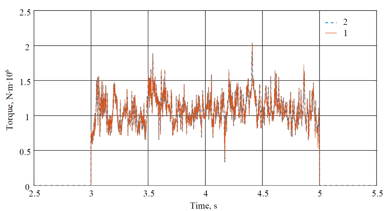
Fig.6. Electromagnetic torque of motor (1) and load torque (2) at load 35 t and speed 1.05 rad/s
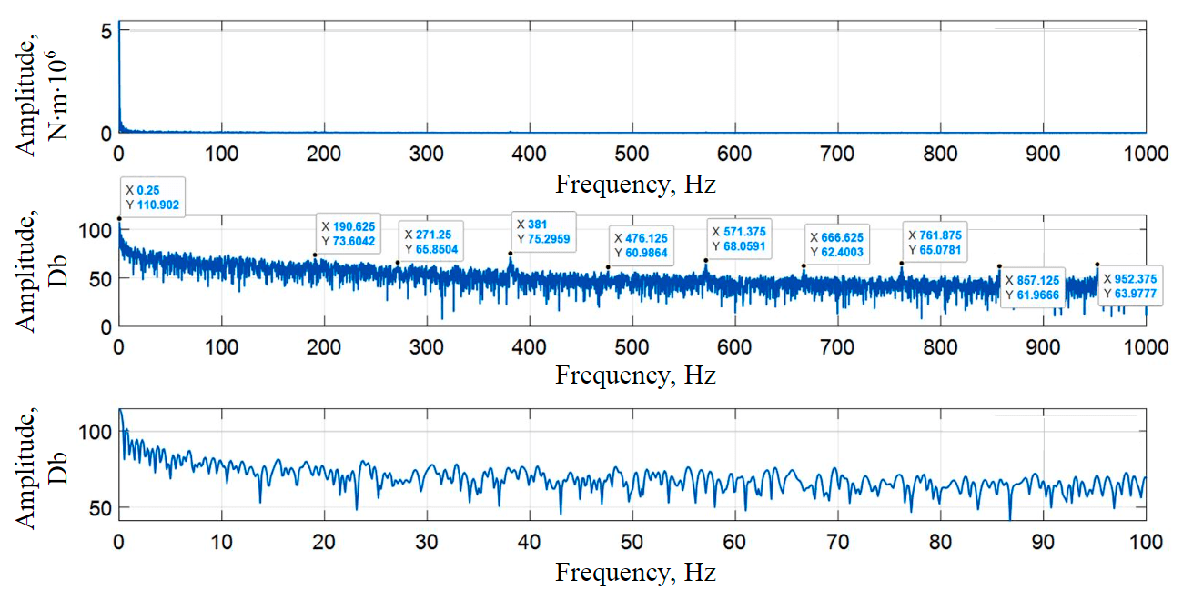
Fig.7. Spectrum of electromagnetic torque at load 35 t and speed 1.05 rad/s
Figures 6, 7 show the results of studies of electric drive of grinding process. Since at this stage of research only steady-state operation mode is considered, in Fig.6 there are no periods of motor acceleration and deceleration. Time interval 3-5 s corresponds to motor operation under load. Accordingly, at time 3 s, the applied load rises, and at 5 s drops. Oscillation amplitude is about 1.5 MN∙m. Increased oscillations of electromagnetic torque lead to motor oscillations and, hence, to vibrations and rotor run-out.
According to research results, growing mill speed allows reducing average torque value. If for current characteristics of ground product such a change will not affect the quality of grinding, this will allow reducing power consumption of electric drive from the network and the oscillation amplitude.
Based on the obtained spectrum in Fig.7 it can be concluded that a periodic component is traced in the signal of electromagnetic torque. In electromagnetic torque spectrum, the same components are traced as in the spectrum of load characteristic; however, there is a shift of recorded peaks along the frequency axis.
Conclusion
Even though mills are, as a rule, designed with a non-controlled electric drive, the effect that can be obtained from adjustable speed is of practical interest. Control of destruction forces can be performed by changing mill rotation speed.
The conducted studies showed that due to integrated modelling of process and electromechanical equipment it is possible to optimize energy consumption. With increasing rotation speed from 0.84 to 1.05 rad/s, impact energy increases ensuring ore destruction. At the same time, load torque values are comparable; thus, it is possible to increase impact energy for grinding without increasing electricity consumption.
From the spectra obtained it is possible to identify mill load condition – speed and fill level.
The developed procedure can be used to determine a more efficient operation mode when changing volumetric fill of the mill due to variability of ore properties. Research results are of practical importance both in mill unit operation, and when designing electromechanical complexes. Studies allow considering specific features of the automation object in development of electric drives of mills. A possibility of obtaining energy effect during mill operation as a result of integrated digital modelling of process and electromechanical equipment is shown. This allows evaluating the impact of grading of some indicators of the technological system on the other indicators of electromechanical system based on fast response of the model during virtual tests. Investigations conducted by the authors can form the basis for creating a comprehensive tool for evaluating the efficiency – energy chain of grinding process links. This idea can be implemented due to one of the key trends of Industry 4.0 – digital modelling.
Further research will focus on evaluation of energy efficiency when changing drum mill operation mode.
References
- Litvinenko V.S. Digital Economy as a Factor in the Technological Development of the Mineral Sector. Natural Resources Research. 2020. Vol. 29, p. 1521-1541. DOI: 10.1007/s11053-019-09568-4
- Filatova I., Nikolaichuk L., Zakaev D., Ilin I. Public-private partnership as a tool of sustainable development in the oil-refining sector: Russian case. Sustainability. 2021. Vol. 13. Iss. 9. N 5153. DOI: 10.3390/su13095153
- Zhukovskiy Y.L., Batueva D.E., Buldysko A.D. et al. Fossil Energy in the Framework of Sustainable Development: Analysis of Prospects and Development of Forecast Scenarios. Energies. 2021. Vol. 14. Iss. 17. N 5268. DOI: 10.3390/en14175268
- Fedoseyev S.V., Tsvetkov P.S. Key factors in public perception of carbon dioxide capture and disposal projects. Journal of Mining Institute. 2019. Vol. 237, p. 361-368. DOI: 10.31897/PMI.2019.3.361
- Cleary P.W., Owen P. Effect of operating condition changes on the collisional environment in a SAG mill. Minerals Engineering. 2019. Vol. 132, p. 297-315. DOI: 10.1016/j.mineng.2018.06.027
- Ruonan Meng, Qinglin Zhao, Miaomiao Wu et al. A Survey and Analysis on Electricity Consumption of Raw Material Mill System in China Cement Industry between 2014 and 2019. Sustainability. 2021. Vol. 13. Iss. 3. N 1126. DOI: 10.3390/su13031126
- Zixin Yin, Tongqing Li, Yuxing Peng, Guiyi Wu. Effect of Lifter Shapes on the Mill Power in a Ball Mill. IOP Conference Series: Materials Science and Engineering. 2018. Vol. 452. Iss. 4. N 042201. DOI: 10.1088/1757-899X/452/4/042201
- Djordjevic N., Shi F.N., Morrison R. Determination of lifter design, speed and filling effects in AG mills by 3D DEM. Minerals Engineering. 2004. Vol. 17. Iss. 11-12, p. 1135-1142. DOI: 10.1016/j.mineng.2004.06.033
- Mishra B.K., Rajamani R.K. The discrete element method for the simulation of ball mills. Applied Mathematical Modelling. 1992. Vol. 16. Iss. 11, p. 598-604. DOI: 10.1016/0307-904X(92)90035-2
- Xiaolei Bian, Guoqiang Wang, Hongdi Wang et al. Effect of lifters and mill speed on particle behaviour, torque, and power consumption of a tumbling ball mill: Experimental study and DEM simulation. Minerals Engineering. 2017. Vol. 105, p. 22-35. DOI: 10.1016/j.mineng.2016.12.014
- Hlungwani O., Rikhotso J., Dong H., Moys M.H. Further validation of DEM modeling of milling: effects of liner profile and mill speed. Minerals Engineering. 2003. Vol. 16. N 10, p. 993-998. DOI: 10.1016/j.mineng.2003.07.003
- Djordjevic N., Shi F.N., Morrison R. Determination of lifter design, speed and filling effects in AG mills by 3D DEM. Minerals Engineering. 2004. Vol. 17. Iss. 11-12, p. 1135-1142. DOI: 10.1016/j.mineng.2004.06.033
- Aleksandrov A.V., Litvinova N.M. Experimental theoretical studies of ore grinding process. Mining Informational and Analytical Bulletin. 2009. Vol. 4. N 12, p. 242-249 (in Russian).
- Bouchard J., Desbiens A., Poulin É. Reducing the energy footprint of grinding circuits: the process control paradigm. IFAC-PapersOnLine. 2017. Vol. 50. Iss. 1, p. 1163-1168. DOI: 10.1016/j.ifacol.2017.08.402
- Aleksandrova T. N., Potemkin V. A. Development of a methodology to assess the hydrocyclone process with account of the rheological properties of the mineral slurry. Journal of Mining Institute. 2021. Vol. 252, p. 908-916. DOI: 10.31897/PMI.2021.6.12
- Alexandrova T.N., Romashev A.O., Kuznetsov V.V. Development of a methodological approach to establishing the floatability of finely disseminated sulfides. Obogashchenie rud. 2020. N 2, p. 9-14 (in Russian). DOI: 10.17580/or.2020.02.02
- Dongling Wu, Wei Chen, Hongjie Yanet al. Identifying grinding mill dynamics using acoustic beamforming and numerical modelling. Powder Technology. 2020. Vol. 371, p. 231-243. DOI: 10.1016/j.powtec.2020.05.092
- Campbell J.J., Holmes R.J., Spencer S.J. et al. The collection and analysis of single sensor surface vibration data to estimate operating conditions in pilot-scale and production-scale AG/SAG mills. Proceedings of the XXII International Mineral Processing Congress, 9 September – 3 October 2003, Cape Town, South Africa. South African Institute of Mining & Metallurgy, 2003, p. 280-288.
- Kuzba B., Pawlosa W., Konieczny A., Krzeminska M. Optimisation Platform for copper ore processing at the Division of Concentrator of KGHM Polska Miedz SA. Mineral Engineering Conference MEC 2016, 25-28 September 2016, Swieradow-Zdroj, Poland. E3S Web of Conferences, 2016. Vol. 8. N 01037. DOI: 10.1051/e3sconf/20160801037
- Korolev N.A., Solovev S.V. AC motor diagnostics system based on complex parametric analysis. International Conference on Mechanical Engineering, Automation and Control Systems 2016, 27-29 October 2016, Tomsk, Russian Federation. IOP Conference Series: Materials Science and Engineering, 2017. Vol. 177. N 012007. DOI: 10.1088/1757-899X/177/1/012007
- Kozjaruk A.E., Vasilev B.U., Shtop S.A., Serdukov N.A. Currents in bearings of induction motors of electric drives with semiconductor converter. 17th International Ural Conference on AC Electric Drives (ACED), 26-30 March 2018, Ekaterinburg, Russia. IEEE, 2018. N 17719959. DOI: 10.1109/ACED.2018.8341707
- Góralczyk M., Krot P., Zimroz R., Ogonowsk S. Increasing Energy Efficiency and Productivity of the Comminution Process in Tumbling Mills by Indirect Measurements of Internal Dynamics – An Overview. Energies. 2020. Vol. 13. Iss. 24. N 6735. DOI: 10.3390/en13246735
- Cleary P.W., Owen P. Effect of operating condition changes on the collisional environment in a SAG mill. Minerals Engineering. 2019. Vol. 132, p. 297-315. DOI: 10.1016/j.mineng.2018.06.027
- Weerasekara N.S., Liu L.X., Powell M.S. Estimating energy in grinding using DEM modelling. Minerals Engineering. 2016. Vol. 85, p. 23-33. DOI: 10.1016/j.mineng.2015.10.013
- Koteleva N., Khokhlov S., Frenkel I. Digitalization in Open-Pit Mining: A New Approach in Monitoring and Control of Rock Fragmentation. Applied Sciences. 2021. Vol. 11. Iss. 22. N 10848. DOI: 10.3390/app112210848
- Beloglazov I.I., Petrov P.A., Bazhin V.Y. The concept of digital twins for tech operator training simulator design for mining and processing industry. Eurasian Mining. 2020. N 2, p. 50-54. DOI: 10.17580/em.2020.02.12
- Boikov A., Payor V., Savelev R., Kolesnikov A. Synthetic data generation for steel defect detection and classification using deep learning. Symmetry. 2021. Vol. 13. Iss. 7. N 1176. DOI: 10.3390/sym13071176
- Vasilyeva N., Fedorova E., Kolesnikov A. Big data as a tool for building a predictive model of mill roll wear. Symmetry. 2021. Vol. 13. Iss. 5. N 859. DOI: 10.3390/sym13050859
- Nikolaev A.V., Vöth S., Kychkin A.V. Application of the cybernetic approach to price-dependent demand response for underground mining enterprise electricity consumption. Journal of Mining Institute. 2022, p. 1-12 (Online first) DOI: 10.31897/PMI.2022.33
- Boikov A.V., Savelev R.V., Payor V.A., Potapov A.V. Evaluation of bulk material behavior control method in technological units using dem. Part 2. CIS Iron and Steel Review. 2020. Vol. 20, p. 3-6. DOI: 10.17580/cisisr.2020.02.01
- Behera B., Mishra B.K., Murty C.V.R. Experimental analysis of charge dynamics in tumbling mills by vibration signature technique. Minerals Engineering. 2007. Vol. 20. Iss. 1, p. 84-91. DOI: 10.1016/j.mineng.2006.05.007
- Peng Gao, Wentao Zhou, Yuexin Hanet al. Enhancing the capacity of large-scale ball mill through process and equipment optimization: An industrial test verification. Advanced Powder Technology. 2020. Vol. 31. Iss. 5, p. 2079-2091. DOI: 10.1016/j.apt.2020.03.001
- Jian Tang, Tianyou Chai, Lijie Zhaoet et al. Soft sensor for parameters of mill load based on multi-spectral segments PLS sub-models and on-line adaptive weighted fusion algorithm. Neurocomputing. 2012. Vol. 78. Iss. 1, p. 38-47. DOI: 10.1016/j.neucom.2011.05.028
- Jian Tang, Lijie Zhao, Heng Yue et al. Vibration analysis based on empirical mode decomposition and partial least square. Procedia Engineering. 2011. Vol. 16. P. 646-652. DOI:10.1016/j.proeng.2011.08.1136
- Gugel K., Palacios G., Ramirez J., Parra M. Improving ball mill control with modern tools based on digital signal processing (DSP) technology. Cement Industry Technical Conference, 2003. Conference Record. IEEE-IAS/PCA 2003, 4-9 May 2003, Dallas, USA. IEEE, 2003, p. 311-318. DOI: 10.1109/CITCON.2003.1204732
- Gugel K.S., Moon R.M. Automated mill control using vibration signal processing. 2007 IEEE Cement Industry Technical Conference Record, 29 April 2007 – 2 May 2007, Charleston, USA. IEEE, 2007, p. 17-25. DOI: 10.1109/CITCON.2003.1204732
- Esteves P.M., Stopa M.M., Cardoso Filho B.J., Galery R. Charge behavior analysis in ball mill by using estimated torque. IEEE Transactions on Industry Applications. 2014. Vol. 51. Iss. 3, p. 2600-2606. DOI: 10.1109/TIA.2014.2377372
- Behera B., Mishra B.K., Murty C.V.R. Experimental analysis of charge dynamics in tumbling mills by vibration signature technique. Minerals Engineering. 2007. Vol. 20. Iss. 1, p. 84-91. DOI: 10.1016/j.mineng.2006.05.007
- Pedrayesa F., Norniellaa J.G., Meleroet M.G. et al. Frequency domain characterization of torque in tumbling ball mills using DEM modelling: Application to filling level monitoring. Powder Technology. 2018. Vol. 323, p. 433-444. DOI: 10.1016/j.powtec.2017.10.026
- Walton O.R., Braun R.L. Viscosity, granular‐temperature, and stress calculations for shearing assemblies of inelastic, frictional disks. Journal of Rheology. 1986. Vol. 30. Iss. 5, p. 949-980. DOI: 10.1122/1.549893
- Thornton C., Cummins S.J., Cleary P.W. An investigation of the comparative behaviour of alternative contact force models during elastic collisions. Powder Technology. 2011. Vol. 210. Iss. 3, p. 189-197. DOI: 10.1016/j.powtec.2011.01.013
- Wensrich C.M., Katterfeld A. Rolling friction as a technique for modelling particle shape in DEM. Powder Technology. 2012. Vol. 217, p. 409-417. DOI: 10.1016/j.powtec.2011.10.057
- Lei Xu, Kun Luo, Yongzhi Zhao et al. Influence of particle shape on liner wear in tumbling mills: A DEM study. Powder technology. 2019. Vol. 350, p. 26-35. DOI: 10.1016/j.powtec.2019.03.033
- Bibak Z., Banisi S. A combined physical and DEM modelling approach to investigate particle shape effects on load movement in tumbling mills. Advanced Powder Technology. 2021. Vol. 32. Iss. 3, p. 916-930. DOI: 10.1016/j.apt.2021.01.034
- Bbosa L.S., Govender I., Mainza A. Development of a novel methodology to determine mill power draw. International Journal of Mineral Processing. 2016. Vol. 149, p. 94-103. DOI: 10.1016/j.minpro.2016.02.009
- Melekhina K.A., Ananyev P.P., Plotnikova A.V. et al. Modeling and Optimization of Complex Ore Pretreatment by Disintegration in Autogenous. Mining Informational and Analytical Bulletin. 2020. N 10, p. 95-105 (in Russian). DOI: 10.25018/0236-1493-2020-10-0-95-105
- Seong-Hyeon Hong, Byoung-Kee Kim. Effects of lifter bars on the ball motion and aluminum foil milling in tumbler ball mill. Materials Letters. 2002. Vol. 57. Iss. 2, p. 275-279. DOI: 10.1016/S0167-577X(02)00778-4
- Osipova N.V. Selecting Parameters of Feed Control Algorithm for Wet Autogenous Mill for Grinding Iron Ore. Mining Informational and Analytical Bulletin. 2021. N 10, p. 146-156 (in Russian) DOI: 10.25018/0236_1493_2021_10_0_146
- Ruonan Meng, Qinglin Zhao, Miaomiao Wu et al. A Survey and Analysis on Electricity Consumption of Raw Material Mill System in China Cement Industry between 2014 and 2019. Sustainability. 2021. Vol. 13. Iss. 3. N 1126. DOI: 10.3390/su13031126
- Belskii A.A., Dobush V.S., Khaikal Sh.F. Operation of a Single-phase Autonomous Inverter as a Part of a Low-power Wind Complex. Journal of Mining Institute. 2019. Vol. 239, p. 564-569. DOI: 10.31897/PMI.2019.5.564
- Sychev Y.A., Zimin R.Y. Improving the quality of electricity in the power supply systems of the mineral resource complex with hybrid filter-compensating devices. Journal of Mining Institute. 2021. Vol. 247, p. 132-140. DOI: 10.31897/PMI.2021.1.14
- Vasilev B.Yu., Shpenst V.A., Kalashnikov O.V., Ulyanov G.N. Providing energy decoupling of electric drive and electric grids for industrial electrical installations. Journal of Mining Institute. 2018. Vol. 229, p. 41-49. DOI: 10.25515/PMI.2018.1.41
- Lvov V., Chitalov L. Semi-Autogenous Wet Grinding Modeling with CFD-DEM. Minerals. 2021. Vol. 11. Iss. 5. N 485. DOI: 10.3390/min11050485