
Renovation method of restoring well productivity using wavefields
- 1 — Senior Lecturer Tyumen Industrial University ▪ Orcid ▪ Elibrary
- 2 — Ph.D. Associate Professor Tyumen Industrial University ▪ Orcid ▪ Elibrary ▪ Scopus
- 3 — Leading Engineer Tyumen State University ▪ Orcid ▪ Scopus
- 4 — Ph.D. Head of Department Tyumen Industrial University ▪ Orcid

Abstract
A stagewise theoretical substantiation of the renovation vibrowave method of influencing the near-wellbore zone of reservoir for restoring well productivity is presented. The area of treatment by the proposed method covers the reservoir with a heterogeneous permeability with fractures formed by fracking. In this method a decrease in concentration of colmatants occurs due to a change in direction of contaminants migration. Under the influence of pressure pulses, they move deep into the reservoir and disperse through the proppant pack. The results of mathematical modelling of the propagation of pressure wave and velocity wave and the calculations of particles entrainment in wave motion are presented.
None
Introduction
The main technological trends in oil fields development according to the Energy Strategy of the RF until 2035 are associated with development of hard-to-recover resources in conditions of low productivity of oil wells. An important characteristic reflecting the ability of a porous medium (including proppant, hydrofracture filler) to filtrate and, hence, the well flow rate, are relative phase permeabilities [1]. As a result of long-term operation, small particles of destroyed rock accumulate in bottomhole area of the well and in near-bottomhole zone [2]; insoluble salts (carbonates, sulphates [3]) can precipitate, which leads to a decrease in permeability in bottomhole space [4, 5] and a decrease in production rate of hydrocarbons as well as an increase in water cuttings of well production. Numerous studies on oil recovery intensification show that the problem is characteristic for most of the exploited fields around the world: Saudi Arabia [6], Bahrain [7], Western Siberia, North Caucasian-Mangyshlak oil and gas province, Goryacheistochnenskoye field, Chechen Republic [8], Krasnodar oil and gas region, fields in the north of the Perm Territory [9].
The method of massive hydrofracturing (HF) implemented as a universal method for increasing the productivity and flow rate of wells [10] is not always efficient; it increases the heterogeneity of the reservoir and often has a short-term or opposite effect. Therefore, integrated methods using combinations of various effects, for example, physical and traditional chemical impact on a problem area, are a relevant alternative to HF.
At present, as regards the physical basis of the integrated method, the use not of a substance (hot water, steam, gas, chemical reagents, etc.), but physical (geophysical) fields of different nature (electromagnetic, elastic vibrations, sound, shock) as a “working agent” on the reservoir is becoming increasingly important. Thus, in [11] three applied methods of elastic hydrostimulation of production are distinguished differing in the depth of impact on the reservoir (Table 1).
Table 1
Classification of elastic actions used to clean the bottomhole zone [11]
|
Type of stimulation |
Influencing factor |
Tool outlet flow as a function of time |
Example of tool |
Penetration depth, inches |
|
Based on pressure |
Rotating jets |
Fixed flow rate |
Jetting-based tool |
≤ 2 |
|
Energy (acoustic) |
Sinusoidal wave generating cavitation process |
Periodical, of sinusoidal shape, low amplitude, and high frequency |
Multi-directional cavitation-based tool (MDCT) |
≤ 6 |
|
Based on acceleration |
Hydraulic pulses with amplitude 2.1-10.5 MPa not exceeding local hydrofracturing pressure |
Periodical, sawtooth, high amplitude and low frequency |
Dynamic Fluid Modulation (DIM) tool |
≤ 36 |
Technological application of stationary repression on the reservoir is considered in [12]; of variable pressure gradient – abroad [13, 14] and in Russia [15-17]. Hydraulic tools of jet and pulsating action [18-20], electrohydraulic devices [21-23], hydrodynamic generators GD2V, seismic hydraulic systems SVS-24/RS27, SV-27/150B “Rusich”, and other devices [24, 25] are developed. The efficiency of applying wave and vibration methods is substantiated and proved in [26-28]. Dynamic pulsation is effective, as it forces the injected fluids to go beyond the path of least resistance through the dispersion process [6] – the working fluid penetrates into the reservoir more evenly (despite the pre-sence of washed paths [29]) and deeper [11]. In this case, the effect is achieved by much lower pressure gradients than with stationary impact.
After vibrowave treatment of wellbore zone (WBZ), the technology provides for the stage of well development in order to extract the destroyed colmatant particles to the surface. This process is energy- and labour-intensive; in the course of its application, environmental problems arise associated with contaminants disposal.
The objective of the study is theoretical substantiation and practical testing of the method of vibrowave treatment of the pay based on the results of the implemented methods and elimination of their shortcomings. The actual task of the research is construction of a physicomathematical model and investigation of the migration of solid colmatating particles for a more detailed interpretation of the process of cleaning the bottomhole zone and porous structure of the reservoir by pressure pulses of high amplitude and low frequency.
Methods
In the course of research, the analysis of publications and geological field material was accomplished, the analytical method and the method of mathematical formalization were used. The object of technological impact by the proposed vibrowave method was the production well with an average history of operation and mechanisms of wellbore zone destruction. Well N 25 is in the Strezhevsky oil-producing region, it is part of the development system of the Yuzhno-Okhteurskoye field lying at the border of the Tomsk region and KhMAO within license block N 19 of the distributed subsoil reserves. In 1992, the field was put into trial operation on reservoirs Yu1-1 and Yu1-3 (Table 2).
Since the specific geological feature of the formation is low reservoir pressure, during the initial opening, drilling mud was lost, the volume of which reached 50 m3. This was the reason for a decrease in phase permeability for oil and gas and well productivity. After three months of well development, fluid inflow was 10-12 m3/day. After hydrofracturing, the well operated for another two months, and the fluid flow rate decreased from 40 to 12 m3/day at the end of the service life.
Table 2
YuZ1 pay parameters
|
Parameters |
Yu1-1 |
Yu1-3 |
|
Average value |
Range |
|
|
Average occurrence depth, m |
2,121 |
2,182 |
|
Type of occurrence |
Layer-uplifted |
|
|
Type of reservoir |
Porous |
|
|
Permeability, 10–3 µm 2 |
7.2 |
1.8 |
|
Initial oil saturation, unit fraction |
0.527-0.639 |
|
|
Residual oil saturation, unit fraction |
0.233-0.38 |
|
|
Gas oil ratio, m3/m3 |
74 |
|
|
Water cut, % |
8 |
|
|
Density, kg/m3 |
832 |
|
|
Reservoir oil saturation pressure, MPa |
8.7 |
|
|
Gas density of standard separation, kg/m3 |
1.32 |
|
Negative consequences of technogenic geodynamics of bottomhole zone of the reservoir (BHR) are as follows: filtration of any process fluid causes aggregation and sedimentation of solid phase with formation of colmatation zones with partial or complete clogging of reservoir pores. After the phase of mechanical colmatation, a period of physicochemical interactions of closely spaced particles begins, when van der Waals laws of electrokinetics come into force leading to even greater compaction of filtration sediment.
The technical task of increasing permeability of wellbore zone leading to an increase in oil recovery is the destruction of the colmatating medium and cleaning of pore space.
The basis of the proposed method of impact is the use of a variable pressure gradient created in the WBZ to influence various structures of colmatants in hydrofracture. Implementation of the method is associated with resolving the following problems: creating a low-frequency vibration effect at the level of perforation area and a directed vibration effect on the colmatant particles in order to destroy its structure; propagation of vibration impact though the reservoir thickness along the hydrofracture; entrainment of colmatant particles in the oscillatory process; migration deep into the reservoir and scattering of particles of destroyed contaminants.
The action mechanism of pressure pulses on a porous medium was investigated by many authors and substantiated by mathematical models in [13, 30 etc.]. Among the solutions of the wave equation for longitudinal waves in a porous medium, in addition to the seismic longitudinal P-wave with low damping, there are slow “diffusion waves” of porosity and pressure described by equations of parabolic type. The porosity wave is about 1-2 orders of magnitude slower than P, liquid in pores almost does not compress, since matrix velocities are slow (frequencies 10–2·100 Hz). Therefore, stresses in the matrix generated by the porosity wave decrease due to the movement of fluid. Diffusion pressure wave is slower than the porosity wave by 1-2 orders; it also has a large period and exists only in conjunction with porosity diffusion [13].
The mechanism of cleaning pore throats is explained based on the features of diffusion waves: due to expansion and contraction of pores, fluid inflow and outflow occurs through the throats destroying the mechanical blockades and advancing interphase boundaries (in case of saturation with two fluids). In practical experiments and industrial well repair technologies [6, 31 etc.] a corresponding change in reservoir parameters and an improvement in reservoir properties are recorded.
The above studies do not consider the migration problem of suspension particles forming in pores as the basis for changing permeability of reservoir matrix. The authors of the article offer their views on the solution of this problem.
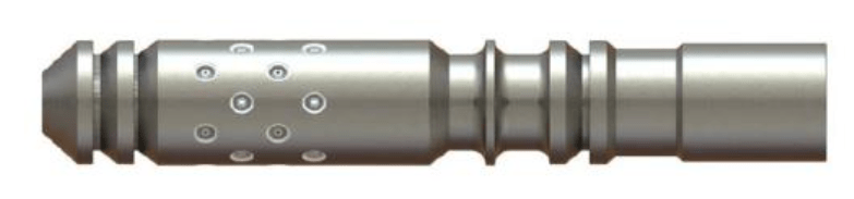
Fig.1. Wave hydromonitor to create well fluid pressure pulses
As a physical source of the investigated vibration impact, a pulsed hydromonitor of the structure was used [32] (Fig.1).
A wave hydromonitor (WHM) is installed at the end of the tubing and converts a uniform movement of the fluid injected into it into a pulsating one. The transformation occurs by the force of compression of springs inside the device followed by ejection of a certain volume of fluid through the WHM nozzles.
Movement of piston in the inner cavity occurs at an increasing speed under the action of increasing fluid flow pressure, which is counteracted by the force of elastic compression of the spring. Due to radially directed impacts of fluid jets ejected through the WHM nozzles, a traveling wave of pressure and velocity arises propagating in the direction of impact in the area of the device placement.
To assess the influence of hydropulse action on the positions of particles of the destroyed colmatant, let us use the analytical method. Let us write down the equation of motion dynamics of a spherical incompressible particle suspended in a Newtonian fluid. Let us first consider a particular case of particle motion in fluid that performs harmonic oscillations, and then pass to a more general case of fluid oscillations under the action of pressure pulses.
In the first rough approximation, we take into account only the greatest force of particle interaction with fluid – Stokes force. Then Newton's II law in projection on the х axis can be written as:
where mp, xp, R are mass, coordinate and radius of the particle; VL, ω, η – velocity amplitude, cyclic frequency of fluid oscillations and dynamic viscosity coefficient of fluid.
Solution of non-homogeneous differential equation of the second order (1) is the sum of general solution of the homogeneous and particular solution of inhomogeneous equation.
General solution of the homogeneous equation
has the form
where Хр0 and Vр0 are the initial position and velocity of particle; – velocity of translational movement of fluid.
We shall look for a particular solution of the inhomogeneous equation in the form xp(t) = = Xacos(ωt – ϕ). Substituting into the original equation, we get:
Using the method of vector diagrams, it is possible to find the amplitude of particle oscillations:
Let us note that VL/ω = XL – is the oscillation amplitude of fluid particles.
You can also find phase shift ϕ. Thus,
At times of high
the exponential summand decays, and the particle will move at the frequency of the driving force with Ха amplitude near position according to the law
A similar expression can be obtained in case of fluid velocity fluctuations according to the law .
Let us introduce the coefficient of particle entrainment in oscillatory motion
where f is fluid oscillation frequency; α ∈ (0; 1).
By expressing f as a function of a and R, it is possible to construct dependencies that determine the size of particles which will participate in the oscillatory motion.
Analysis of hydromonitor operation taking into account the time of piston movement allows presenting a graph of changes in pressure created in near-wellbore zone as a sequence of symmetrical trapezoidal pulses with steep fronts (Fig.2).
Анализ работы гидромонитора с учетом времени перемещения поршня позволяет представить график изменения давления, создаваемого в прискважинной зоне, в виде последовательности симметричных трапецеидальных импульсов с крутыми фронтами (рис.2).
In Fig.2, T is pulse repetition period, A amplitude of pulses, Т1 pulse duration at the base of the trapezoid, for a symmetrical pulse the durations of the leading and trailing edges are the same and equal to 0.5 (Т1 – Т0); Т0 – duration of the pulse top.
The function in Fig.2 can be presented as a Fourier series expansion:
The graph of the investigated function (10) is symmetrical with respect to the time axis, therefore bn = 0.
Fourier coefficients for the trapezoidal function:
where Т0, Т1, Т and А are parameters of pressure pulses; .
To determine the desired pressure field P(x, t) in the first rough approximation, we will take into account only the diffusion pressure wave using the piezoconductivity equation.
Initial-boundary value problem for the piezoconductivity equation:
Boundary conditions
Initial condition:
where P0 is reservoir pressure.
Let us seek the solution as a function:
Solution of the initial problem for piezoconductivity equation (12) has the following form:
where an, a0, S(ξ) are Fourier series coefficients,
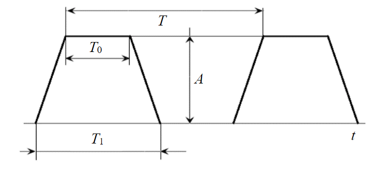
Fig.2. Model presentation of pressure pulses generated by hydromonitor
Let us analyse function (14): at large times, the summands containing the exponents in a negative power containing time, will tend to zero. Therefore, for the steady state we have:
Equations (6) and (8) show that in order to determine the particle coordinate, it is necessary to know fluid velocity amplitude VL. To calculate it in a rough approximation, let us use the Darcy law which relates pressure drop and true fluid velocity:
where K0 is absolute permeability of porous medium, m2; ms – porosity; μ – dynamic viscosity of liquid, Pa.s.
Applying (16) in the one-dimensional case to (15), we obtain:
Comparing (8) and (17), we get the expression for the particle coordinate:
где
Discussion of results
One operation cycle of wave hydromonitor used as a source of the investigated impact [32] (see Fig.1) takes 0.5-1 s depending on pressure. Therefore, the frequency of impact on the reservoir will be 1-2 Hz. The time of transient processes bet-ween the “open-closed” positions is incomparably short compared to the time of fluid ejection into the annular space and the relaxation time. Therefore, the graph of pressure changes created in wellbore zone can be presented as a sequence of symmetrical trapezoidal pulses with steep fronts (Fig.2).
In the simulation model, the period is chosen in accordance with the frequency of WHM pulses [32] T = 0.5 s. Parameters T1 = = 0.25 с, T0 = 0.18 s are chosen by analogy with the shape of vibrator pulse given in [33]. Bottomhole pressure monitoring log given in [34] makes possible an approximate determination of pulses amplitude. Thus, the boun-dary condition for (12) has the form shown in Fig.3.
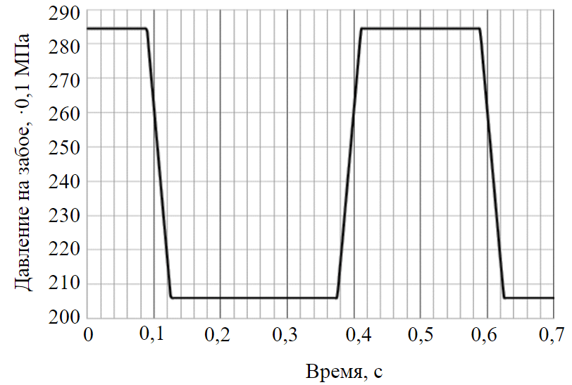
Fig.3. Bottomhole pressure pulses formed by hydromonitor
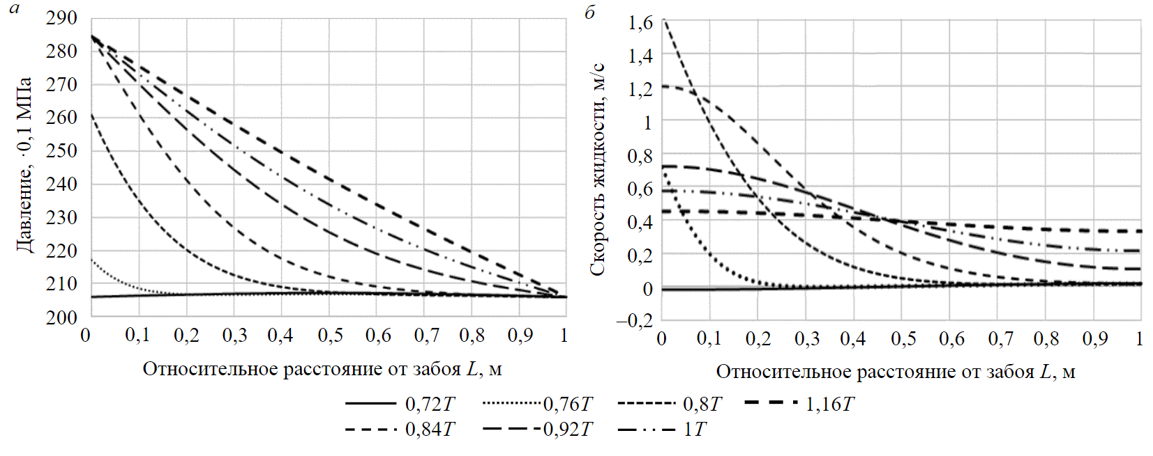
Fig.4. Propagation of pressure (a) and velocity (b) disturbance in the formation fracture depending on relative distance and relative time
Since pressure pulses have an amplitude of about 8 MPa and a frequency of 1-2 Hz, wave hydromonitor of design [32], in accor-dance with classification [11], is a Dynamic Fluid Modulation (DIM) tool (see Table 1).
A hydrofracture filled with proppant was chosen as the space in which the colmatant particles are moving. To solve the research problems, let us calculate the entrainment of particles in wave motion and determine the character of their motion in the fracture part in a one-dimensional approximation.
Source data for calculation: vibration frequency 2 Hz (T = 0.5 s), T1 = 0.25 s, T0 = 0.18 s; the analysed impact penetration distance L = 20 m; formation pressure 205 atm; pressure pulse generated by hyd-romonitor 80 atm; permeability of fracture filler 150 D; porosity 0.15; dynamic viscosity of formation fluid 1 mPa·s; density of colmatant particles material 2,650 kg/m3.
Design charts of pressure and velocity of compressible fluid in hydrofracture are shown in Fig.4. Perturbation is considered within the duration of the pressure pulse generated by the WHM (see Fig.3).
Graph in Fig.4, a shows propagation of pressure disturbance in a one-dimensional space associated with a hydrofracture. Pressure distribution profile becomes linear over the duration of the pulse amplitude.
According to the velocity change graphs (Fig.4, b), at the time of pulse start, fluid particles begin to move in the wellbore space deep into the reservoir at high velocity. The rest of particles in the impact area at this time are at rest or move at low velocities. As the pressure profile equalizes, all fluid particles begin to move, their velocity tends to a constant value by the end of the pulse.
Graphs in Fig.4 show that, under the assumptions made, porous structures at a distance of 20 m from the bottom face are subjected to the force impact of the WHM vibropulses. Movement of fluid particles is a superposition of fast oscillatory motion near the centre of oscillation and slow movement together with the centre of oscillation deep into porous medium under the action of a time-average well-reservoir pressure drop .
Let us consider the influence of the wavefield on colmatant particles in the wellbore zone.
In the pore space, contaminant particles can simultaneously occur in two states – as a settled colmatating medium that changes the reservoir properties and a suspension freely circulating in the intrapore space. The task of vibration impact is to initiate the suffusion process, disrupt the structures of the colmatated layer with separation of solid particles and their transition into suspension.
Impact pressure was calculated using N.E.Zhukovsky's formula for describing hydroshock in the annular space [35]. The value of shock pressure varying in a pulsed mode from 205 to 285 MPa according to the studies [33], is sufficient to open fractures. Since less effort is needed to destroy the colmatating structures than to open fractures, vibrowave action with indicated initial parameters can be considered efficient.
The question of geological dynamics of porous media in the process of fluid filtration was investigated in [36, 37], a conclusion was made about particle sizes in the filtered suspension (Table 3).
Table 3
Results of the study of permeability during colmatant filtration using natural core samples [36]
|
Characteristic of samples |
Sizes of particles in filtered suspension, µm |
Maximum depth of particle penetration into sample, mm |
Decrease of sample permeability as a result of pore channels colmatation, % |
|
Medium-grained sandstone with maximum pore channel diameter 50 µm |
1-2 |
80 |
20 |
|
4-6 |
25-40 |
45 |
|
|
8-12 |
10-15 |
36 |
|
|
16-20 |
2-3 |
12 |
|
|
30-40 |
Do not penetrate |
– |
|
|
Fine-grained sandstone with maximum pore channel diameter 32 µm |
1-2 |
60 |
32 |
|
4-6 |
15-20 |
46 |
|
|
8-12 |
3-4 |
15 |
|
|
16-20 |
Do not penetrate |
– |
|
|
Fine-grained clayey sandstone with maximum pore channel diameter 20 µm |
1-2 |
3-4 |
14 |
|
4-6 |
1-2 |
8 |
|
|
8-12 |
Do not penetrate |
– |
In accordance with Table 3, the maximum diameters of penetrating particles and diameters of pore channels are related as 1:5-1:2.5. For the fracture filler with permeability of 150 D, the diameter of pore channels [38] is:
According to these conclusions, let us perform further analysis for particles with diameters varying from 1-2 to 30-40 µm.
When a pulse action occurs, after time (7) the particles will reach a steady state of motion which, according to (18), is a superposition of translational and oscillatory motion. For particles with diame-ter of 2 mm or less, the transition process time does not exceed 2 s = 4Т = 4 in relative units.
If we assume that a massive suspension particle which is close to a spherical shape moves after a linearly viscous oscillating fluid under the action, mainly, of the Stokes force, then it is possible to introduce value a (entrainment coefficient) equal to the ratio of spatial amplitude of oscillations of the particle and fluid. From the calculation results of fluid velocity fields, nomograms were plotted (Fig.5).
The entrainment coefficient a can vary from 0 to 1; α= 0 = 0, the oscillatory motion of fluid does not affect the particle; at α = 1 = 1, the particle is completely entrained by the wave. For calculations, a narrower range of change in α – coefficient was used – from 0.2 to 0.8, in which the most confident effect is recorded.
According to the obtained nomograms, vibrowave action confidently covers particles with radius of 0.3-0.8 mm and less, while particle diameters in the filtered suspension, according to Table 3, vary from 1-2 to 30-40 µm. This conclusion is confirmed by the calculation of dependence of the particle coordinate on time (Fig.6).
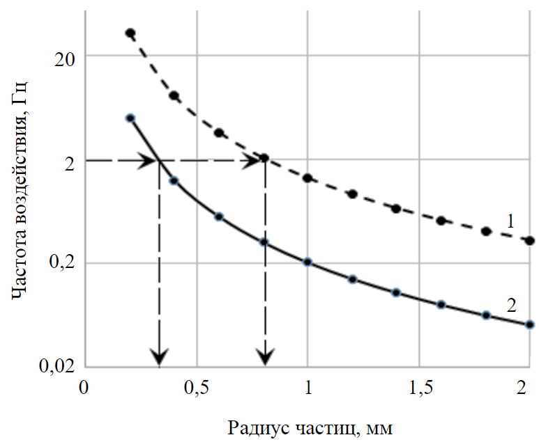
Fig.5. Frequency of vibration impact entraining particles of R radius in oscillatory motion with entrainment degree 0.2 (1) and 0.8 (2)
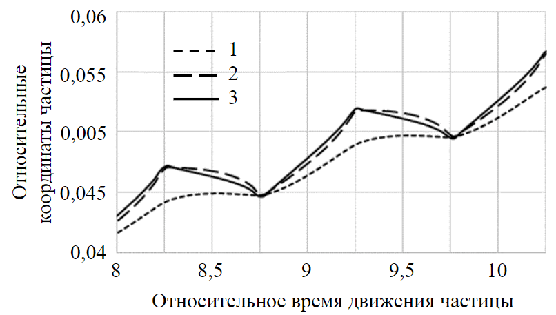
Fig.6. Relative coordinate of solid colmatant particles counted from bottomhole (L lengths) depending on their diameters and relative time of vibropulse action (T periods) 1 – d = 1 mm; 2 – 100 µm; 3 – 1 µm
Particles covered by the influence of the wavefield of traveling wave begin to move under the action of vibrational forces in the direction of influence. Their concentration in the problematic wellbore zone decreases, which contributes to the opening of filtration channels and an increase in their permeability. In addition, the reduction of contaminant particles contributes to a more intense penetration of pulsating fluid from the well into the reservoir, greater efficiency of bottomhole space cleaning and an increase in the size of vibration impact zone to the far boundary of the proppant pack.
Example of application in the field
Technological implementation of theoretical studies at well N 25 of the Yuzhno-Okhteursky field involves the following operations:
- wave hydromonitor is lowered to the well bottom in the perforation interval on the tubing;
- elastic fluctuations of jet pressure are created to obtain a field of low-frequency traveling waves in wellbore zone and in porous medium of the proppant pack of hydrofracture by injecting the working fluid (water, oil, acids, alkalis, etc.) through the swivel into the tubing and through the hydromonitor;
- hydromonitor is moved at a velocity of 10-40 cm/min with continuous supply of working fluid to the tubing for a stepwise vibropulse treatment of the perforation interval.
The impact of pulsating fluid flow injected through the wave generator-hydromonitor is enhanced by chemical treatment of wellbore zone. As a result, the wellbore layer which colmatates the perforations is destroyed with partial dissolution of contaminants.
Application of the technology was controlled by a depth manometer-thermometer. According to its readings, after pumping 20 m3 of working fluid, wellhead injection pressure dropped to atmospheric pressure, which indicates the destruction of the contaminants blockade and opening of filtration channels from the clean zone of the reservoir to the wellbore space. After additional pumping of working fluid in a volume of 15 m3, an increase in injection pressure occurred with appearance of circulation through the annulus as a fountain manifestation of oil and gas.
As a result of vibrowave impact on the wellbore zone, an increase in oil production of 6 t/day was obtained. According to the data of the company, additional oil production for 3.5 months amounted to 630 t, profit from the implentation was 3.5 mln roubles. After 12 months, additional oil production amounted to 2,050 t [34].
Conclusion
Conclusion. In the course of the study, the following results were obtained: formulas (15), (17) were derived and graphs of pressure waves propagation and fluid velocity in the study area were plotted (Fig.4); the correspondence of sizes of particles entrained into wave motion with sizes of pore channels for the initial conditions was determined (Table 3, formula (19); theoretical conclusions were made about the sizes of solid colmatant particles effectively entrained into wave motion (formula (9) and Fig.5 ); the dependence (18) of the coordinate of colmatant particles experiencing vibropulse action on time is derived; the degree of wave action influence on particles of different sizes within the studied zone of porous structure is estimated (Fig.6); practical implementation of vibrowave treatment method in the form of a sequence of technological operations is substantiated.
The performed mathematical calculations show the migration of suspension particles forming in pores as a result of the impact of hydraulic pulses on wellbore zone of the reservoir in the direction from the disturbance source. This leads to a decrease in their concentration in the wellbore zone and an increase of its permeability. This effect is indirectly corroborated in practice [6, 36, 38] (flow rate or fluid absorption by the well increases during and after treatment).
Thus, in the course of research, a theoretical substantiation and practical testing of the method of vibrowave treatment of the pay was accomplished. A characteristic feature of the proposed method is the advancement of the destroyed colmatant particles deep into the reservoir along the hydrofracture and their dispersion outside the proppant pack. In this case, there is no need to bring the destroyed contaminants to the surface, and re-contamination of near-wellbore zone with cleaning products is excluded.
The method can be used not only to increase the productivity of production wells, but also to increase the injectivity of injection wells transferred from the stock of production wells to maintain reservoir pressure. Compared to traditional vibration methods, it has a long-term effect and can be reproduced as the reservoir properties deteriorate.
Introduction of the method can be one of the options for import substitution of jet and pulsating installations [18-20], electro-hydraulic devices [21-23], which is relevant in modern conditions of the industry development.
Quantitative assessment of the distribution of particles along the wellbore zone in the process of vibration impact is of scientific and practical interest. For this, while carrying-on the study, it is advisable to consider a quantitative description of the process taking into account the transition of solid particles from the settled mass to suspension and back.
References
- Shabarov A.B., Shatalov A.V., Markov P.V., Shatalova N.V. Relative Permeability Calculation Methods in Multiphase Filtration Problems. Tyumen State University Herald. Physical and Mathematical Modeling. Oil, Gas, Energy. 2018. Vol. 4. N 1, p. 79-109 (in Russian). DOI: 10.21684/2411-7978-2018-4-1-79-109
- Belonogov E.V., Korovin A.Y., Yakovlev A.A. Increase in Intake Capacity by Dynamic Operation of Injection Wells. Journal of Mining Institute. 2019. Vol. 238, p. 405-409. DOI: 10.31897/PMI.2019.4.405
- Saychenko L., Tananykhin D., Ashena R. Prevention of scale in the downhole equipment and productive reservoir during the oil well operation. Journal of Applied Engineering Science. 2021. Vol. 19. Iss. 2, p. 363-368. DOI: 10.5937/jaes0-29696
- Rogov E.A. Study of the well near-bottomhole zone permeability during treatment by process fluids. Journal of Mining Institute. 2020. Vol. 242, p. 169-173. DOI: 10.31897/PMI.2020.2.169
- Zaitsev M.V., Mikhailov N.N. Impact of Formation Damage Effects on Non-Monotonic Dependence of a Well Flow-Rate on Depression. Oilfield Engineering. 2016. N 6, p. 7-13 (in Russian). DOI: 10.24887/0028-2448-2017-9-90-94
- Davidson B., Kolli K., Spanos T. et al. Dynamic Fluid Pulsation: A Novel Approach to Reservoir Stimulation Improves Post-Stimulation Gains. SPE Kingdom of Saudi Arabia Annual Technical Symposium and Exhibition, 23-26 April 2018, Dammam, Saudi Arabia. SPE, 2018. N SPE-192283-MS. DOI: 10.2118/192283-MS
- Al Harthy A., Al Habsi K., Al Hinai K., Walley S. The First Middle East Unconventional Well Stimulation Treatment by Applying WASP® Technology: Field Cases. SPE Middle East Oil and Gas Show and Conference, 18-21 March 2019, Manama, Bahrain. SPE, 2019. N SPE-195057-MS. DOI: 10.2118/195057-MS
- Bakraev M.M., Bulyukova F.Z., Dumler E.B., Delbiev A.S. Research of Methods for Intensification of Oil Production From Lower Cretaceous Sedimentsof Goryacheistochnenskoe Fiel. Bulletin of the Tomsk Polytechnic University. Geo Аssets Engineering. 2021. Vol. 332. N 3, p. 126-134 (in Russian). DOI: 10.18799/24131830/2021/3/3108
- Galkin V.I., Martyushev D.A., Ponomareva I.N., Chernykh I.A. Developing features of the near-bottomhole zones in productive formations at fields with high gas saturation of formation oil. Journal of Mining Institute. 2021. Vol. 249, p. 386-392. DOI: 31897/PMI.2021.3.7
- Votinov A.S., Drozdov S.A., Malysheva V.L., Mordvinov V.A. Recovery and increase of the productivity of wells of Kashirskiy and Podolskiy reservoirs of the certain Perm region oil field. Perm Journal of Petroleum and Mining Engineering. 2018. Vol. 18. N. 2, p. 140-148 (in Russian). DOI: 10.15593/2224-9923/2018.4.4
- Nagar A., Davidson B., Srivastava P. et al. Effective Wellbore Cleanup and Improvement of Injection Performance and Conformance Using Coil Tubing Conveyed Tool for Waveform Dominated Fluid Dispersion and Pin-Point Chemical Placement During Well Stimulation. SPE/ICoTA Well Intervention Conference and Exhibition, 24-25 March 2020, The Woodlands, USA. SPE, 2020. N SPE-199812-MS. DOI: 10.2118/199812-MS
- Khuzin R.R., Andreev V.E., Mukhametshin V.V. et al. Influence of hydraulic compression on porosity and permeability properties of reservoirs. Journal of Mining Institute. 2021. Vol. 251, p. 688-697. DOI: 10.31897/PMI.2021.5.8
- Spanos T.J.T., Dusseault M.B., Udey N. Fundamental Thermodynamic Requirements for Porous Media Description. Elsevier Geo-Engineering Book Series. 2004. Vol. 2, p. 513-521. DOI: 10.1016/S1571-9960(04)80092-2
- Diaz Viera M.A., Sahay P., Coronado M., Ortiz Tapia A. Mathematical and Numerical Modeling in Porous Media: Applications in Geosciences (1st ed.). Boca Raton: CRC Press, 2012. DOI: 10.1201/b12080
- Kvasov I.N., Fetisov K.Yu., Aleksandrov M.A., Gladenko A.A. Well productivity and reservoir recovery enhancement with using vibration wave impact technology. Oil and Gas Studies. 2021. N 4, p. 73-83 (in Russian). DOI: 10.31660/0445-0108-2021-4-73-83
- Evstigneev D.S., Savchenko A.V. Analysis of Filtration Models in Porous Media Inclusive of Harmonic Wave Impact. Interekspo Geo-Sibir. 2018. Vol. 6, p. 29-42. DOI: 10.18303/2618-981X-2018-6-29-42
- Evstigneev D.S., Savchenko A.V. Effect of Virbo-Wave Stimulation on Two-Phase Filtration Flow in Oil-Saturated Specimen. Fundamentalnye i prikladnye voprosy gornykh nauk. 2017. Vol. 4. N 1, p. 94-100 (in Russian).
- Ahmed B., Khoshnaw F.A., Raza M. et al. New Type of Fluidic Oscillator Made Clean Out Operation Environment Friendly and Cost Effective – A Case Study that Converted Failure into a Success. International Petroleum Technology Conference, 21-23 February 2022, Riyadh, Saudi Arabia. OnePetro, 2022. N IPTC-22265-MS. DOI: 10.2523/IPTC-22265-MS
- Ahmed B., Khoshnaw F.A., Raza M. et al. Adaptation of Technologies Making Clean out Operations Environment Friendly and Cost Effective – Converting Failure into Success Using New Type of Fluidic Oscillator. SPE Annual Technical Conference and Exhibition. OnePetro, 2021. N SPE-206099-MS. DOI: 10.2118/206099-MS
- Al Binhaji Z., Al Ghamdi A., Sabut B., Hicks D. A Novel Approach to Uniformly Acid Stimulate Carbonate Tight Formation Utilizing Multi Jetting Tool Technology. SPE International Conference and Exhibition on Formation Damage Control, 19-21 February 2020, Lafayette, USA, OnePetro, 2020. DOI: 10.2118/199244-MS
- Habibi A., Fensky C., Perri M. et al. Unplugging Standalone Sand Control Screens with High-power Shock Waves: An Experimental Study. SPE International Conference and Exhibition on Formation Damage Control, 19-21 February 2020, Lafayette, USA. SPE, 2020. N SPE-199294-MS. DOI: 10.2118/199294-MS
- Habibi A., Fensky C.E., Fattahpour V. et al. The role of fouling materials strength on unplugging sand control devices using an electrohydraulic stimulation technique. Journal of Petroleum Science and Engineering. 2022. Vol. 208. Part E. N 109689. DOI: 10.1016/j.petrol.2021.109689
- Habibi A., Fensky C.E., Perri M. et al. Unplugging Standalone Sand-Control Screens Using High-Power Shock Waves. SPE Drilling & Completion. 2021. Vol. 36. Iss. 2, p. 398-412. DOI: 10.2118/199294-PA
- Turbakov M.S., Shcherbakov A.A. Efficiency Improvement of Vibrowave Devices Impact on the Bottomhole Formation Zone for the Intensification of Oil Recovery. SPE Annual Caspian Technical Conference & Exhibition, 4-6 November 2015, Baku, Azerbaijan. OnePetro, 2015. N SPE-177376-MS. DOI: 10.2118/177376-MS
- Khuzin R.R., Zakirov R.A., Andreev V.E. et al. Patent N RU 2768225 C2. Reusable hydropulse module for treatment of bottomhole space of reservoir. Published 23.03.2022.
- Bazhaluk Ya.M., Voloshyn Y.D. New technology for the intensification of oil and gas recovery from depleted and marginal wells. ResearchFate GmBH. 2019. URL: https://www.researchgate.net/publication/339303147_NEW_TECHNOLOGY_FOR_ THE_INTENSIFICATION_OF_OIL_AND_GAS_RECOVERY_FROM_DEPLETED_AND_MARGINAL_WELLS (accessed 11.12.2022)
- Escobar-Remolina J.C., Barrios-Ortiz W. et al. An Effective Accelerated Pulsing Injection Method for Restoring Injectivity in Waterflood Fields with Selective Injection Systems with Side-Pocket Mandrels and Control Flow Valves. SPE Western North American and Rocky Mountain Joint Meeting, 17-18 April 2014, Denver, Colorado. OnePetro, 2014. N SPE-169544-MS. DOI: 10.2118/169544-MS
- Kurlenya M.V., Penkovskii V.I., Savchenko A.V. et al. Development of Method for Stimulating Oil Inflow to the Well during Field Exploitation. Journal of Mining Science. 2018. Vol. 54, p. 414-422. DOI: 10.1134/S1062739118033810
- Gale T., Thomson N.R., Barker J.F. An Investigation of the Pressure Pulsing Reagent Delivery Approach. Groundwater Monitoring & Remediation. 2015. Vol. 35. Iss. 2, p. 39-51. DOI: 10.1111/gwmr.12102
- Spanos T.J.T., Udey N. The Physics of Composite and Porous Media. The Physics of Composite and Porous Media. Boca Raton: CRC Press, 2017. DOI: 10.1201/9781351228329
- Al-Tammer H., Al-Ghafli H., Davidson B., Abouakar A. Introduction of Newly Deployed Wellbore Cleaning Technique. SPE International Conference and Exhibition on Formation Damage Control, 19-21 February 2020. OnePetro, 2020. N SPE-199331-MS. DOI: 10.2118/199331-MS
- Ananev V.A., Apasov T.K., Pasov G.T. et al. Patent No. RU 139424 U1. Wave hydrometer. Published 20.04.2014.
- Gadiev S.M. Use of vibration in oil production. Moscow: Nedra, 1977, p. 159 (in Russian).
- Apasov T.K., Apasov G.T., Nesterov S.V. et al. Analysis of treatment of bottomhole space of reservoir at wells of the Khokhryakovskoye field. Geologiya i neftegazonosnost' Zapadno-Sibirskogo megabasseina (opyt, innovatsii): materialy Mezhdunarodnoi nauchno-tekhnicheskoi konferentsii. Tyumen: Tyumenskii industrialnyi universitet, 2016, p. 16-18 (in Russian).
- Apasov T.K., Shatalova N.V., Shatalov A.V. Substantiation of the Efficiency of the Vibrowave Technology of Impact on a Bottomhole Oil Formation Zone. Automation, Telemechanization and Communication in Oil Industry. 2020. N 9 (566), p. 44-49 (in Russian). DOI: 10.33285/0132-2222-2020-9(566)-44-49
- Mikhailov N.N. Information and technological dynamics of near-wellbore zones. Moscow: Nedra, 1996, p. 339 (in Russian).
- Zaitsev M.V., Mikhailov N.N., Popov S.N. Influence of Mechanical-Chemical Factors of a Formation Damage on Wells Productivity. Oilfield Engineering. 2017. N 6, p. 33-38 (in Russian).
- Tiab D., Donaldson E.C. Petrophysics: Theory and practice of measuring reservoir rock and fluid transport properties. Elsevier, 2015, p. 895. DOI: 10.1016/C2014-0-03707-0