
Model of a walking sampler for research of the bottom surface in the subglacial lake Vostok
- 1 — Ph.D. Leading Researcher Saint Petersburg Mining University ▪ Orcid
- 2 — Ph.D. Scientific Supervisor of Laboratory SC «Arctic» Saint Petersburg Mining University ▪ Orcid
- 3 — Ph.D., Dr.Sci. Professor Saint Petersburg Mining University ▪ Orcid
- 4 — Ph.D. Assistant Lecturer Saint Petersburg Mining University ▪ Orcid
- 5 — Laboratory Researcher Saint Petersburg Mining University ▪ Orcid

Abstract
Technologies and technical means for investigation of subglacial lakes in Antarctic is a new developing scientific and technical direction, which today has no clearly established methodology. Based on the developed technology of drilling a new access well to lake Vostok and its penetration as well as analysis of existing methods and devices for bottom sediment sampling, a basic model of a sampler with a walking-type mover, capable of moving along different trajectories and operating in a wide technological range, is proposed. The proposed device model is equipped with different actuators for sampling the bottom surface with different physical and mechanical properties. Based on the presented basic model of the walking sampler, a mathematical model of the device was developed, which was based on the theoretical mechanics methods. As a result of conducted research the dependencies were obtained, which allow making a scientifically justified choice of optimal values for geometric and force parameters of the walking sampler. A conceptual design of the walking sampler has been developed, taking into account the mutual location and coupling of its main components, the overall dimensions of the delivery tool, as well as the esthetic component of the device.
None
Introduction
For more than 50 years, “Vostok” station has been the centre of Russian scientific research in Antarctic, the results of which are followed by the entire world scientific community [1].
The discovery of lake Vostok in the second half of the twentieth century [2] posed new scientific and technical problems, the solution of which was aimed at its penetration and further study. During the whole period of works, approximate data were obtained and assumptions about morphometric characteristics of the water body [3-5], composition, age and thickness of sediments [6-8], as well as water circulation in it were made [9].
The transition of drilling to congelation ice, which is a layer of frozen lake water, as well as taking samples of frozen lake water from the well after its penetration made it possible to estimate many parameters of the water column [10]. However, bottom sediments, their composition and thickness are of the greatest interest [11-13]. Obtaining even a small amount of material from the bottom of a subglacial lake will allow solving many scientific problems [11-16], the main one being the search for signs of living organisms in the lake [17].
To date, two projects for sampling bottom sediments from subglacial water bodies in Antarctic have been successfully implemented – WISSARD [18, 19] and SALSA [20]. However, the technical solutions applied in these projects [21, 22] cannot be used in the study of the relic lake Vostok due to its unique characteristics.
Analysis of existing technical means for investigation of water bodies and underwater field development allowed to formulate basic requirements for sampler design taking into account previously developed technology of subglacial lake penetration [23-25], access well parameters, technology of device delivery to the bottom surface, technology of device connection to the glacier surface [26, 27], and lake Vostok characteristics: depth, bottom relief, presence and velocity of underwater currents [28, 30].
One of the stages in creating an experimental prototype sampler for the investigation of lake Vostok bottom sediments is the development of a digital prototype device to simulate the processes of its delivery to the bottom surface and sampling of bottom sediments. The obtained information will allow evaluating the proposed technical solutions in terms of reliability, environmental safety, etc. and based on the results of the investigation, making appropriate adjustments to the design of the experimental sampler.
Existing devices for sampling bottom sediments of Antarctic subglacial lakes are mainly represented by coring samplers, which can be classified by principle of operation into gravity and gravity-piston, impact, piston, self-synchronizing vibrating, dynamic-balanced [31-33].
In spite of experimentally established advantages of coring samplers, they have a common disadvantage – during one tripping operation, sometimes reaching several hours under “Vostok” station conditions, a sample taken directly under the well is delivered to the surface. Thus, the obtained information is not representative and does not give a complete picture of the bottom surface. Therefore, taking into account sufficient carrying ability of the lake bottom, as well as its presumably flat relief directly under “Vostok” station, it is reasonable to use movers that are capable to provide the device relocation and multiple sampling of bottom sediments.
For exploration of the bottom surface and development of mineral deposits in the seas and oceans, tracked, wheeled, auger, vibrational, stepping and other types of movers are used [34]. However, specified operating conditions make most of the above-mentioned movers practically unusable or ineffective due to inability to guarantee preservation of the relic ecosystem integrity in the lake Vostok bottom due to aggressive mechanical impact on the ground, leading to destruction of the surface layer and turbidity of water.
The analysis of known moving methods for bottom units [34] has shown the prospects of using double-supported stepping devices (stepping movers), providing work on any ground, including soils with difficult relief, with high passability, environmental safety, ease of operation and allowing to work in a wide technological range [35, 36]. At the same time, the stepping process of the device can be ensured by changing the position of the system centre of mass by moving the counterweight, which can be used as the working body of the device.
Methodology
Dependence of the working body weight (counterweight) on the geometric and force parameters of the walking device
When designing a walking sampler (walking device) it is necessary to coordinate the design parameters of this device with the dimensions of the delivery module and the way of its transportation to the bottom surface of the subglacial lake Vostok [26]. Taking into account the lack of experience in design and operation of such samplers, the task was to develop a calculation technique, which could be used as a basis for further design of such devices as experience in design and operation accumulates.
As a base case, a model of a stepping two-support sampler is adopted, whose complete stepping cycle includes three stages: turning (lifting) of the carrier frame relative to one of the supports in the vertical plane, turning of the carrier frame relative to the given support in the horizontal plane and turning (lowering) of the carrier frame relative to the same support in the vertical plane [34-36]. Only the first stage of the device movement is considered in the article.
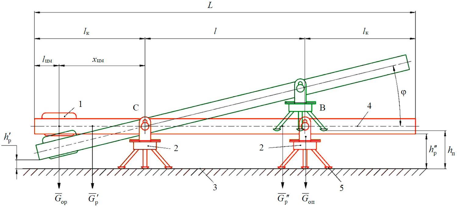
Fig.1. Calculation scheme of a walking sampler
The calculation scheme for the force loading of a walking sampler is shown in fig.1. Here 1 – working body (counterweight); 2 – support; 3 – bottom surface; 4 – carrier frame; 5 – support shoe; С, В – hinge centres of the left and right supports; L – total length of carrier frame, m; lc – console length, m; lcm – length of the carrier frame section from its end to the working body centre of mass, m; хcm – distance from the centre of the support hinge C to the working body centre of mass, m; l – length of the working section of the carrier frame, m; Gwb – working body gravity force, N; Gsup – support gravity force, N; Gf¯' – gravity force of the console to the left of centre C, N; q – weight of 1 m carrier frame, N/m; Gf¯'' – gravity force of the carrier frame to the left of centre C, N; hl – height of support lift when walking, m; hf¯'' – vertical distance from the bottom surface to the carrier frame, m; hf¯' – vertical distance from the bottom surface to the lowered part of the carrier frame when walking, m; φ – rotation angle of the carrier frame in the vertical plane when the sampler is walking in relation to its original (horizontal) position, degrees.
In this type of device, the frame is turned by changing the position of the system centre (carrier frame, supports and working body) by moving the working body onto the left or right console. The weight of the working body required to create the tipping torque relative to centres C or B is determined when the force, with which one of the supports acts on the bottom surface, is equal to zero.
The equilibrium equation for a walking sampler when the force, with which the right support acts on the bottom surface, is zero (the ultimate state characterizing the beginning of the walking process) (Fig.1) is:
where xcm=lc-lcm; Gf'=qlc; Gf''=q(l+lc).
The dependence of the working body weight on the geometric and force parameters of the walking sampler, taking into account equation (1), is represented as:
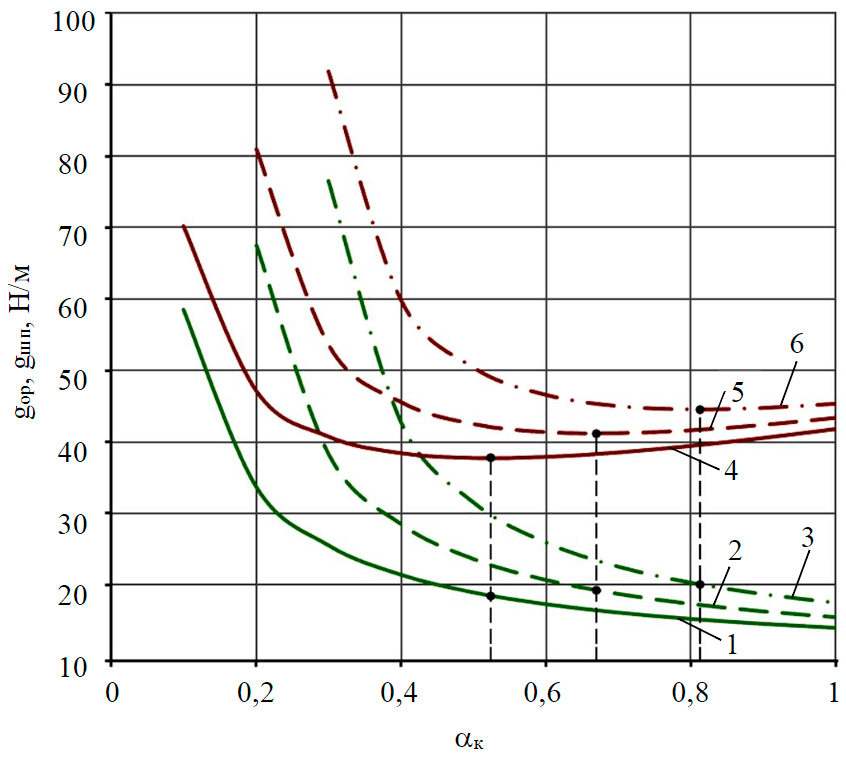
Fig.2. Plots of dependencies of the standardized weight of the working body gwb (1-3) and total standardized weight of the walking device gws (4-6) on dimensionless console coefficient αc at gsup/q = 0.05 and αcm = 0 (1,4); 0.1 (2,5); 0.2 (3,6)
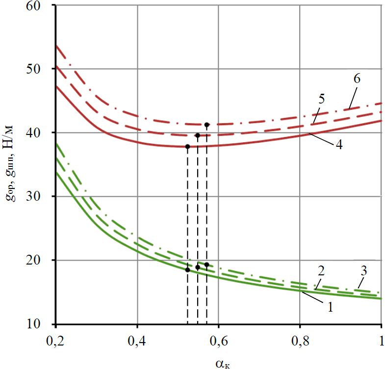
Fig.3. Plots for the standardized weight of the working body gwb (1-3) and total standardized weight of the walking device gws (4-6) on dimensionless console coefficient αc at αcm = 0 and gsup/q = 0.05 (1,4); 0.1 (2,5); 0.15 (3,6)
The expression for the normalized weight of the working body, obtained from dividing equation (2) by the length of the working section of the carrier frame, is as follows:
where gwb = Gwb/l – standardized weight of the working body, N/m; αc = lc/l – dimensionless console coefficient; αcm = lcm/l – dimensionless coefficient of working body position; gsup = Gsup/l – standardized weight of the support, N/m.
The dimensionless console coefficient refers to the ratio of the console length to the length of the working section of the carrier frame. When αc = 0, the length of the console is zero; when αc = 1, it is the length of the working section of the carrier frame. The dimensionless coefficient of the working body position is the ratio of the length of the carrier frame section from its end to the centre of mass of the working body to the length of the working section of the carrier frame. When αcm = 0, the working body centre of mass is at the end of the carrier frame, i.e. in the leftmost position (Fig.1). When αcm = 1, the working body centre of mass coincides with the centre of the hinge of the left support C.
Coefficient of working body position indirectly describes the overall dimensions of the working body, the contours of which, for design reasons, should not protrude beyond the carrier frame.
Based on expression (3), it is found that the standardized weight of the working body of the walking sampler for a given length of the carrier frame depends on the dimensionless coefficients of the console αc and the of the working body position αcm. The minimum size of the walking device is provided at average values for the weight of 1 m carrier frame q = 9 N/m and the ratio of the standardized weight of the support to the weight of 1 m carrier frame gsup/q = 0.05.
Plots of the standardized weight of the working body gwb when changing the console coefficient αc between 0 and 1 for three values of the coefficient of working body position αcm: 0; 0.1; 0.2, considering the adopted values q and gsup/q, are shown in Fig.2 (curves 1-3).
Analysis of curves 1-3 in Fig.2 shows that with increasing console length, i.e. the dimensionless coefficient αc, the standardized weight of the working body gwb decreases hyperbolically. At αc = 0.2, αcm = 0 and previously accepted values of q and gsup/q the standardized weight of the working body gwb = 33.8 N/m, and at αc = 0.6 gwb = 17.3 N/m.
As the working body moves towards the centre of the hinge of the left support C, i.e. as the coefficient αcm increases, the standardized weight of the working body increases. With αc = 0.6, αcm = 0 and the previously adopted values q and gsup/q, gwb = 17.3 N/m, but at αcm = 0.1 gwb = 20.7 N/m, and at αcm = 0.2 gwb = 25.9 N/m.
When the position of the centre of mass of the working body coincides with the left end of the carrier frame (αcm = 0) and at average value of weight of 1 m carrier frame q = 9 N/m dependence graphs of standardized working body weight gwb at change of console coefficient αc in range from 0 up to 1 and three values for ratio of standardized support weight to weight of 1 m carrier frame gsup/q: 0.05; 0.1; 0.15 (Fig.3, curves 1-3) are plotted.
Graphs in Fig.3 show that the standardized weight of the working body gwb decreases sharply with the increase of dimensionless coefficient αc. So at αc = 0.2, gsup/q = 0.05 and adopted earlier values q and αcm gwb = 33.8 N/m, but at αc = 0.6 gwb = 17.3 N/m. In addition, an increase in the gsup/q ratio results in an increase in the standardized weight of the working body. At αc = 0.6, gsup/q = 0.05 and adopted values of q and αcm gwb = 17.3 N/m, but at gsup/q = 0.1 gwb = 18 N/m, and at gsup/q = 0.15 gwb = 18.8 N/m.
Based on the analysis of the curves in Fig.2 and 3, it was found that the value of the standardized weight of the working body gwb should be chosen depending on the ratio of the console length to the length of the working section of the carrier frame αc. If αc → 0, the length of the consoles is reduced, whereas the standardized weight of the working body increases and the total weight of the device grows accordingly. If αc → 1, the length of the consoles is increased and the standardized weight of the working body is reduced, but the total weight of the device is increased due to the increase in the length of the consoles. As a consequence, the optimum console coefficient should be determined to ensure that the total weight of the device is minimal.
The expression for the total weight of the walking sampler is:
where Gws – total weight of the walking sampler, N; Gf = qL – carrier frame weight, N.
After reducing equality (4) to a standardized value (by dividing by l), taking into account formula (3) and the previously adopted notations, the expression for the total standardized weight of the walking device takes the form:
where gws=Gws/l – total standardized weight of the walking device, N/m.
Considering the previously adopted values q = 9 N/m, gsup/q = 0.05 at αcm = 0-0.2 and q = 9 N/m, αcm = 0 at gsup/q = 0.05-0.15 the graphs of varying total standardized weight of the walking sampler gws depending on the console coefficient αc (Fig.2 and 3, curves 4-6) were plotted. The obtained curves have a non-linear (parabolic) character, the minimum values of which correspond to the optimum values of the console coefficient.
In order to calculate the optimum values of the console coefficient corresponding to the minimum values of the total standardized weight of the walking device, the first derivative of the total standardized weight of the walking sampler (5) by the dimensionless console coefficient should be equated to zero:
As a result of differentiation, the optimum console coefficient is determined according to the formula:
The choice of optimal value for the console coefficient depends on the design layout of the device and geometric parameters of the delivery module of the walking sampler to the surface of lake Vostok [26]. When the position of the working body's centre of mass is changed xcm (see Fig.1), i.e. the working body is moved from the end of the carrier frame to the centre of the hinge of the left support C (αcm → 1), the value of the console coefficient ac increases, which results in increase of the standardized working body weight gwb and the total standardized weight of the walking sampler gws (see Fig.2). At αcm = 0 and adopted values q = 9 N/m and gwb/q = 0.05 αc = 0.52, gwb = 18.4 N/m, gws = 37.8 N/m, but at αcm = 0.1 αc = 0.67, gwb = 19.3 N/m, gws = 41.2 N/m, and at αcm = 0.2, αc = 0.81, gwb = 20 N/m, gws = 44.5 N/m. The console coefficient, and with it the standardized weight of the working device and the total standardized weight of the device, increase due to the increase of gsup/q ratio (Fig.3). At gsup/q = 0.05 and accepted values q = 9 N/m and αcm = 0 αc = 0.52, gwb = 18.4 N/m, gws = 37.8 N/m, but at gsup/q = 0.1 αc = 0.55, gwb = 18.9 N/m, gws = 39.5 N/m, and at gsup/q = 0.15 αc = 0.57, gwb = 19.3 N/m, gws = 41.2 N/m.
In the process of bottom sediment sampling the standardized weight of the working body gwb and the total standardized weight of the walking sampler gws increase due to the added mass of the samples taken. As a consequence, with the same previously selected optimum value of the console coefficient αc the coefficient of the working body position αcm increases (Fig.2 and 3). Consequently, at the given console length lc the distance xcm, necessary for creation of the tipping torque relative to the centre C by the increased standardized weight of the working body gwb (see Fig.1), is decreased. For example, before bottom sediment sampling (see Fig.2) at αc = 0.52, gwb = 18.4 N/m, gws = 37.8 N/m, αcm = 0, xcm = lc, but given the samples taken at αc = 0.52, gwb = 22.8 N/m, gws = 42.1 N/m, αcm = 0.1, xcm = 0.81lc or gwb = 29.8 N/m, gws = 49.2 N/m, αcm = 0.2, xcm = 0.62lc.
Equations of the rotation angle for the carrier frame of the walking sampler in the vertical plane
In addition to the above mentioned parameters, a significant influence on the realization of a stable walking process is caused by the rotation angle for the carrier frame of the walking sampler relative to the support in the vertical plane. The rotation angle for the carrier frame in the vertical plane during the device walking is limited by the condition of free transfer of the raised support over the roughness of the bottom surface and the condition of non-contact between the working body or the carrier frame and the ground when the working body is at the end of the console (see Fig.1). If at least one of these conditions is not met, the trajectory of the device should be changed to ensure further walking.
In order to realize the first condition, there should be sufficient gap between the support shoes and the crests of the rough bottom. Therefore, the support lifting height hl includes the maximum height of the bottom roughness, the length of which in the direction of support movement is less than the length (step) of the movement itself, and the minimum gap between the support shoes and the crest of the roughness when the support is lifted. The height hl determines the rotation angle for the carrier frame in the vertical plane during walking (see Fig.1):
The condition of the non-contact for the working body and the carrier frame with the ground is fulfilled, if the maximum lowering of the console is limited by the vertical distance from the bottom surface to the lowered part of the carrier frame during walking. In this case, the permissible rotation angle of the carrier frame in the vertical plane during walking is
The distance h'f includes the maximum height of the roughness, the length of which along the carrier frame does not exceed the console length (the support shoes lean onto the even bottom surface), and the minimum permissible gap between the working body or the support frame and the crest of the roughness.
In order to ensure the walking process of the device, conditions (7) and (8) should be fulfilled at the same time. In expressions (7) and (8), the bottom relief characteristic and the length of the working section of the carrier frame, which are the main design parameters, should be considered as the initial parameters.
Thus, predetermining the rotation angle range for the carrier frame in the vertical plane will not only enable efficient walking control, but also allow to correctly design of the joint between the support and the carrier frame to ensure that it rotates relative to the support by the required angle.
Dependence of dimensionless lifting coefficient on dimensionless gap coefficient
Due to the limited dimensions of the walking sampler, the optimum relationship between the vertical distance from the bottom surface to the carrier frame in the initial (horizontal) position of the carrier frame h''f, the support lifting height hl and the vertical distance from the bottom surface to the lowered part of the carrier frame when walking h'f (see Fig.1) should be found:
After transforming the relations (9), a final expression in dimensionless form for determining the lifting height of the support during walking is obtained:
where β1=h1/h''f – dimensionless lifting coefficient; βf=hf/hf'' – dimensionless gap coefficient.
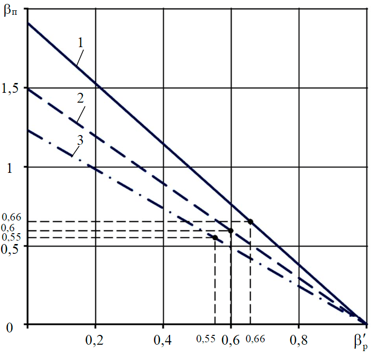
Fig.4. Plots for the dependence of dimensionless lifting coefficient βl on dimensionless gap coefficient β'f at gsup/q = 0.05 and αc = 0.52 (1); 0.67 (2); 0.81 (3)
The dimensionless lifting coefficient is the ratio of the lifting height of the support during walking to the vertical distance from the bottom surface to the carrier frame. The dimensionless gap coefficient is the ratio of the vertical distance from the bottom surface to the lowered part of the carrier frame during walking to the vertical distance from the bottom surface to the carrier frame.
According to expression (10), the graphs for the variation of the lifting coefficient βl with a variation of the gap coefficient β'f from 0 to 1 and with the three previously calculated optimum values of the console coefficient αc, equal to 0.52; 0.67 and 0.81, are shown in Fig.4.
The analysis of the graphs in Fig.4 shows that when β'f=1(h'f=h''f) the carrier frame is in its original (horizontal) position and leans on both supports, βl = 0 (hl = 0) (see Fig.1). As the coefficient β'f decreases (h'f→0), the value of coefficient βl increases (hl > 0), i.e. the carrier frame rotates (rises) relative to the left support in the vertical plane. In case β'f=0 (h'f=0) the left console of the carrier frame leans onto the ground and the value of the lifting coefficient βl is the maximum for the given size of the walking device. In this case the walking process is not possible, because the condition of non-contact between the working body and the carrier frame with the ground is not fulfilled.
The curves shown in Fig.4 are linear in nature and allow the support lifting height to be determined depending on the vertical distance between the bottom surface and the lowering console. With increasing console coefficient αc at the same vertical distances from the bottom surface to the carrier frame hf'' and the lowering part of the carrier frame hf', the support lifting height during walking hl decreases. If hf'' and hl are equal, the vertical distance from the bottom surface to the lowered part of the carrier frame hf' decreases as the console coefficient αc increases. With constant hf' and hl the vertical distance from the bottom surface to the carrier frame hf'' increases with an increase in the console coefficient αc.
The graphs in fig.4 have characteristic matching points for the values of the dimensionless lifting and gap coefficients depending on the console coefficient: at αc = 0.52 βf'=β1=0.66; at αc = 0.67 βf'=β1=0.6 and at αc = 0.81 βf'=β1=0.55 , which corresponds to equality h1=hf'.
Thus, the curves in Fig.4 allow determining, for given values of the console coefficient αc, the optimum ratios between the vertical distance from the bottom surface to the carrier frame hf'' and the lowered part of the carrier frame hf', as well as the height of the support lifting hl, necessary to select rational parameters of the walking device, having limitations both in length and in height.
Digital model of the walking sampler
Based on the mathematical model of the walking sampler described by dependencies (3), (6)-(8), (10), a solid-state modelling of the walking device was carried out in the Autodesk Inventor software. In the process of creating 3D model of the walking device the dimensions of the delivery module (inner diameter 220 mm and length 1 m) were taken into account with regard to its placement in the limited space of the well.
Considering the average values of dimensionless console coefficient αc = 0.67 and rotation angle of the carrier frame at support lifting during walking φ = 10° calculated on the basis of the mathematical model, this problem was solved by contextual creation of 3D models of the walking sampler elements in the assembly mode. The key tools were the copy object function (Fig.5) and the geometry projection in the sketching mode (Fig.6).
The 3D model was created using the parametric modelling function. For example, parameters such as “leg length” and “leg angle” were changed to determine the location of the support legs, which allowed combining these parameters to select the best design for the given conditions (Fig.7).
In the future, this approach will allow to change the geometry of all elements of the walking sampler by changing the input data.
Results of the research
The following results were obtained in the course of this research, the aim of which was to scientifically justify the choice of geometrical and force parameters for the bottom sediment sampling device of the subglacial lake Vostok:
- based on an analysis of existing methods and devices for bottom sediment sampling, a two-support walking sampler model is adopted as a base case;
- calculation scheme for the force loading of the walking device is compiled;
- mathematical model of the walking sampler was developed for a justified design scheme of the walking device, taking into account the developed technology for drilling the access well to lake Vostok, its penetration, as well as geomorphological characteristics of the lake itself;
- analysis of the obtained mathematical formulas, in particular for the standardized weight of the working body and the total standardized weight of the walking sampler, indicates the need to choose rational geometric and force parameters of the device, depending on its structural layout and the geometric parameters of the delivery module, limiting the overall dimensions of the walking device;
- In accordance with the results of mathematical modelling, the development of a complete digital prototype of the walking sampler, which is a virtual prototype of the resulting device and serves to optimize and validate it, has been initiated;
- 3D modelling of a walking sampler in Autodesk Inventor has resulted in a parametric digital model of the walking device. The geometric parameters of the device have been selected, which are optimal for the given operating conditions.
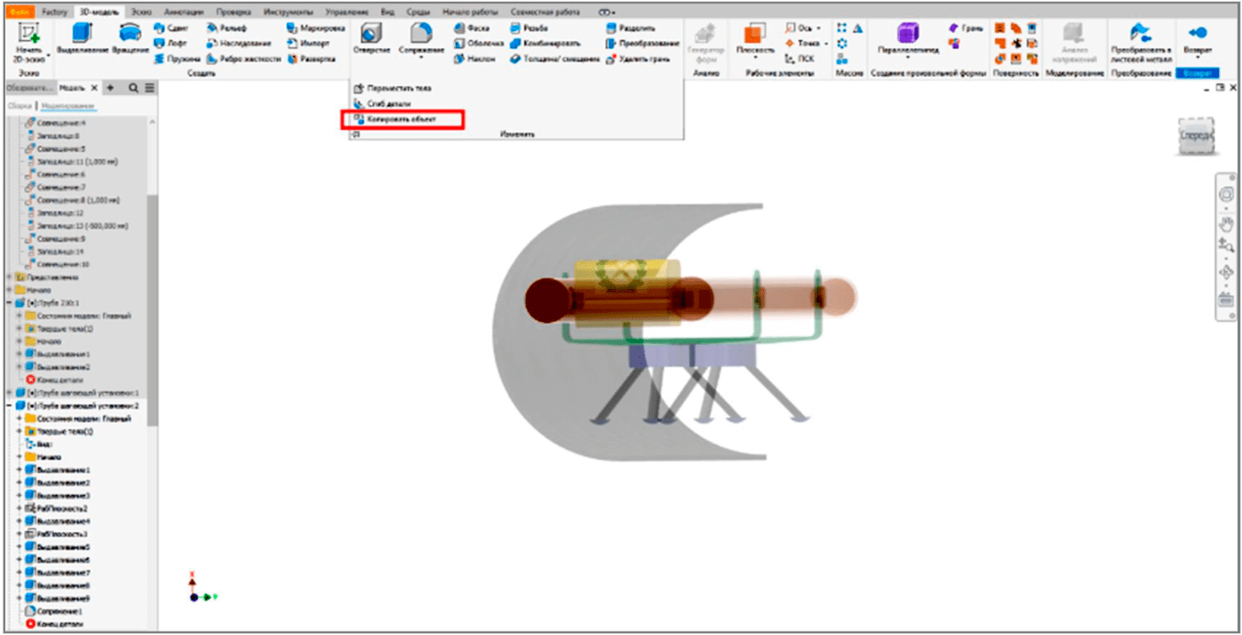
Fig.5. Operation “Copy object”
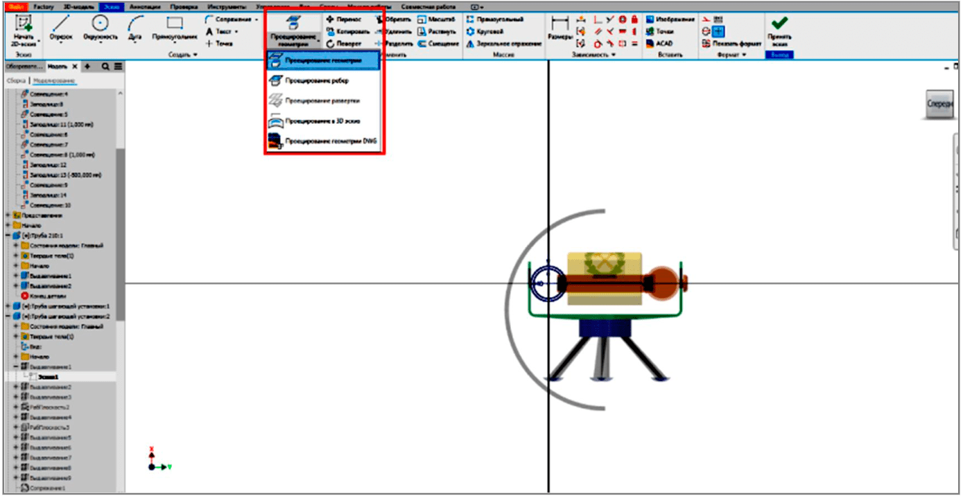
Fig.6. Projection of geometry
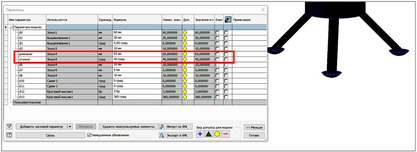
Fig.7. Parametric modelling of the support
Conclusions
The need for comprehensive research of the subglacial lake Vostok and the paleoclimate of the Earth in the area of the Russian Antarctic “Vostok” station is noted in the Strategy for Development of Activities of the Russian Federation in the Antarctic until 2030, approved by Order of the Russian Government N 1767-r of 30 June 2021.
The resulting bottom sediment samples will serve as unique primary material for basic research in geology, biology, paleoclimatology, etc., which will strengthen the primacy of Russian science in Antarctic exploration.
A critical approach to the use of existing experience with mechanical and other types of sea and ocean bottom sampling devices is needed in the design of technical tools for research.
The subglacial lake Vostok is a unique natural system, the research of which requires ensuring the environmental safety of the conducted works, as well as reliable and uninterruptible operation of technical means. One of the main challenges is to create a near-bottom device that ensures, in addition to efficient sampling operation, environmental safety and accident-free movement in the presence of possible (unidentified) bottom obstacles in the sampling area, the device dimensions being strictly limited to the well diameter (from 129 to 250 mm).
The developed mathematical model of the walking sampler allows optimizing its design, taking as an optimization criterion the minimum weight of the device with regard to fitting the design into the given dimensions, limited by the dimensions of the delivery module, and ensuring the process of walking on the bottom surface. Further mathematical modelling of the walking sampler is connected with analysis of its dynamics and durability calculations of its main elements taking into account the attached mass of the bottom sediment samples.
Using digital prototype technology to create a 3D model of a walking device will allow conducting most of the walking sampler testing virtually before it becomes a real object. Being able to identify errors early in the design process will save a significant amount of time and costs for creating physical prototypes of the device.
Some of the next steps in the development of the solid digital model of the walking sampler will be dynamic modelling, parametric calculation of the stress-strain state, visualization, automatic generation and updating of design documentation.
References
- Litvinenko V. Foreword: Sixty-year Russian history of Antarctic sub-glacial lake exploration and Arctic natural resource development. Chemie der Erde. 2020. Vol. 80. Iss. 3. N 125652. DOI: 10.1016/j.chemer.2020.125652
- Kapitsa A.P., Ridley J.K., de Q.Robin G. Large deep freshwater lake beneath the ice of central East Antarctica. Nature. 1996. Vol. 381. N 6584, p. 684-686. DOI: 10.1038/381684a0
- Popov S.V., Sheremetev A.N., Masolov V.N., Lukin V.V. The shoreline of subglacial lake Vostok and adjacent water bodies: interpretation of radio-location profiling data. Materialy glyatsiologicheskikh issledovanii. 2005. Iss. 98, p. 73-80 (in Russian).
- Popov S.V., Lunev P.I. Orography of the Bedrock Relief of Subglacial Lake Vostok and Its Vicinity (East Antarctic). Geomorfologiya. 2012. N 1, p. 81-91 (in Russian). DOI: 10.15356/0435-4281-2012-1-81-91
- Masolov V.N., Popov S.V., Popkov A.M., Lukin V.V. The Bottom Topography and Subglacial Lake Vostok Water Body, East Antarctica. Doklady Earth Sciences. 2010. Vol. 433. N 2, p. 1092-1097. DOI: 10.1134/S1028334X10080222
- Leichenkov G.L., Belyatskii B.V., Popkov A.M., Popov S.V. The geological nature of the subglacial lake Vostok in East Antarctic. Materialy glyatsiologicheskikh issledovanii. 2005. N 98, p. 81-91 (in Russian).
- Popov S.V., Masolov V.N., Lukin V.V., Popkov A.M. National Seismic, Radar and Seismological Studies of Subglacial Lake Vostok. Ice and Snow. 2012. Vol. 52. N 4, p. 31-38 (in Russian). DOI: 10.15356/2076-6734-2012-4-31-38
- Leitchenkov G.L., Antonov A.V., Luneov P.I., Lipenkov V.Y. Geology and environments of subglacial Lake Vostok. Philosophical Transactions of the Royal Society. A Mathematical Physical and Engineering Sciences. 2016. Vol. 374. Iss. 2059. N 0302. DOI: 10.1098/rsta.2014.0302
- Kazko G.V., Savatyugin L.M., Sokratova I.N. Modelling water circulation in the Antarctic subglacial lake Vostok. Ice and Snow. 2012. Vol. 52. N 4, p. 86-91 (in Russian). DOI: 10.15356/2076-6734-2012-4-86-91
- Lipenkov V.Y., Ekaykin A.A., Alekhina I.A. et al. Evolution of climate, glaciation and subglacial environments of Antarctica from the deep ice core and Lake Vostok water sample studies (Key results of implementation of the Russian Science Foundation project, 2014-2016). Ice and Snow. 2017. Vol. 57. N 1, p.133-141 (in Russian). DOI: 10.15356/2076-6734-2017-1-133-141
- Leychenkov G.I., Popkov A.M. Predicted Sedimentary Section of Subglacial Lake Vostok. Ice and Snow. 2012. Vol. 52. N 4, p. 21-30 (in Russian). DOI: 10.15356/2076-6734-2012-4-21-30
- Popov S.V., Masolov V.N., Lukin V.V. Lake Vostok, East Antarctic: glacier thickness, lake depth, subglacial and bedrock relief. Ice and Snow. 2011. N 1 (113), p. 25-35 (in Russian).
- Vasilev N.I., Lipenkov V.Y., Dmitriev A.N.et al. Results and Characteristics of 5g Hole Drilling and the First Tapping of Lake Vostok. Ice and Snow. 2012. Vol. 52. N 4, p. 12-20. DOI: 10.15356/2076-6734-2012-4-12-20
- Vasilev N.I., Leichenkov G.L., Zagrivnyi E.A. Prospects of obtaining samples of bottom sediments from subglacial lake Vostok. Journal of Mining Institute. 2017. Vol. 224, p. 199-208. DOI: 10.18454/PMI.2017.2.199
- Vasilev N.I., Dmitriev A.N., Lipenkov V.Y. Results of the 5G borehole drilling at russian antarctic station «Vostok» and researches of ice cores. Journal of Mining Institute. 2016. Vol. 218, p. 161-171 (in Russian).
- Lukin V.V. Path to exploring the waters of Lake Vostok. Problemy Arktiki i Antarktiki. 2012. N 1 (91), p. 5-19 (in Russian).
- Bulat S.A., Marie D., Petit J.-R. Prospects for life in the subglacial lake Vostok, East Antarctica. Ice and Snow. 2015. Vol. 52, p. 92-96 (in Russian). DOI: 10.15356/2076-6734-2012-4-92-96
- Siegert M. Proposed Exploration of Subglacial Lake Ellsworth. Antarctica Final Comprehensive Environmental Evaluation. British Antarctic Survey. Technical report. Lake Ellsworth Antarctica, 2012, p. 87.
- Fricker H., Powell R., Priscu J. et al. Siple Coast Subglacial Aquatic Environments: The Whillans Ice Stream Subglacial Access Research Drilling Project. Antarctic Subglacial Aquatic Environments (Geophysical Monograph Series). 2011. Vol. 192, p. 199-219. DOI: 10.1002/9781118670354.ch12
- Bolshunov A.V., Vasiliev N.I., Timofeev I.P. et al. Potential technological solution for sampling the bottom sediments of the subglacial lake Vostok: relevance and formulation of investigation goals. Journal of Mining Institute. 2021. Vol. 252, p. 779-787. DOI: 10.31897/PMI.2021.6.1
- Siegert M., Clarke R., Mowlem M. Clean access, measurement, and sampling of Ellsworth Subglacial Lake: A method for exploring deep Antarctic subglacial lake environments. Reviews of Geophysics. 2012. Vol. 50. Iss. 1. RG000361. DOI: 10.1029/2011RG000361
- Tulaczyk S., Mikucki J., Siegfried M. et al. WISSARD at Subglacial Lake Whillans, West Antarctica: Scientific operations and initial observations. Annals of Glaciology. 2014. Vol. 55. Iss. 65, p. 51-58. DOI: 10.3189/2014AoG65A009
- Vasiliev N.I., Dmitriev A.N., Blinov P.A. Drilling of a deep bore-hole at Vostok station (East Antarctica). Vestnik Otdtltnia nauk o Zemle. 2012. Vol. 4. NZ2001 (in Russian). DOI: 10.2205/2012NZ000111
- Litvinenko V.S. Unique technics and technology for well drilling in Antarctic ice. Journal of Mining Institute. 2014. Vol. 210, p. 5-10 (in Russian).
- Litvinenko V.S., Vasiliev N.I., Lipenkov V.Ya. et al. Special aspects of ice drilling and results of 5G hole drilling at Vostok station, Antarctica. Annals of Glaciology. 2014. Vol. 55. Iss. 68, p. 173-178. DOI: 10.3189/2014AoG68A040
- Bolshunov A.V., Vasilev N.I., Timofeev I.P. et al. Potential technological solution for sampling the bottom sediments of the subglacial lake Vostok: relevance and formulation of investigation goals. Journal of Mining Institute. 2021. Vol. 252, p. 779-787. DOI: 10.31897/PMI.2021.6.1
- Litvinenko V.S., Leitchenkov G.L., Vasiliev N.I. Anticipated sub-bottom geology of Lake Vostok and technological approaches considered for sampling. Geochemistry. 2020. Vol. 80. Iss. 3. N 125556. DOI: 10.1016/j.chemer.2019.125556
- Masolov V.N., Lukin V.V., Sheremetev A.N., Popov S.V. Geophysical Investigation of the Subice Lake Vostok in East Antarctica. Doklady Akademii nauk. 2001. Vol. 379. N 5, p. 680-685 (in Russian).
- Lastochkin A.N., Popov S.V., Popkov A.M. Relief of the subglacial basin of Lake Vostok (East Antarctic). Vestnik Sankt-Peterburgskogo universiteta. 2003. N 3, p. 38-50 (in Russian).
- Popov S.V., Chernoglazov U.B. Subglacial lake Vostok, East Antarctic: Shoreline and surrounding bodies of water. Ice and Snow. 2011. N 1, p. 13-24 (in Russian).
- Kalinin I.S., Butov I.I., Zhuravlev A.S., Buyanov M.I. Validation of Choice of an Underwater Core Sampler for Seafloor Placers. Mining Informational and Analytical Bulletin. 2015. N 11, p. 250-256 (in Russian).
- Smolov Yu.S. Techniks for sampling understurbed underwater sediments is represented. Perspectives of its complety are considered. Geology and Mineral Resources of World Ocean. 2015. N 1 (39), p. 80-90 (in Russian).
- Da Gong, Xiaopeng Fan, Yazhou Li et al. Coring of Antarctic Subglacial Sediments. Journal of Marine Science and Engineering. 2019. Vol. 7. Iss. 6. N 194. DOI: 10.3390/jmse7060194
- Timofeev I.P. Walking machines for seabed resource development. Leningrad: Izd-vo Leningradskogo universiteta, 1987, p. 176 (in Russian).
- Timofeev I.P., Sokolova G.V., Korolev I.A. et al. Patent N 2601880 RF. Walking device for underwater mining. Publ. 10.11.2016. Bul. N 31 (in Russian).
- Timofeev I.P., Sokolova G.V., Kolton G.A. et al. Patent N 166446 RF. Walking drilling rig. Publ. 27.11.2016. Bul. N 33 (in Russian).