
Monitoring of compressed air losses in branched air flow networks of mining enterprises

Abstract
Compressed air as a type of safe technological energy carrier is widely used in many industries. In economically developed countries energy costs for the production and distribution of compressed air reach 10 % of the total energy costs. The analysis of compressed air production and distribution systems in the industrial sector shows that the efficiency of the systems is at a relatively low level. This is due to the fact that insufficient attention is paid to these systems since the compressed air systems energy monitoring has certain difficulties – the presence of complex and branched air pipeline networks with unique characteristics; low sensitivity of the equipment which consumes compressed air; the complexity of auditing pneumatic equipment that is in constant operation. The article analyzes the options for reducing the cost of production and compressed air distribution. One of the promising ways to reduce the compressed air distribution cost is timely detection and elimination of leaks that occur in the external air supply network of the enterprise. The task is solved by hardware-software monitoring of compressed air pressure at key points in the network. The proposed method allows real-time detecting of emerging air leaks in the air duct network and sending commands to maintenance personnel for their timely localization. This technique was tested in the industrial conditions of ALROSA enterprises on the air pipeline network of the Mir mine of the Mirninsky Mining and Processing Plant and showed satisfactory convergence of the calculated leakage values with the actual ones. The practical significance of the obtained results is that the developed method for monitoring air leaks in the air duct network is simple, it requires an uncomplicated software implementation and allows to localize leaks in a timely manner, thereby reducing unproductive energy costs at the enterprises.
None
Introduction
Because of its versatile properties, compressed air is one of the main energy carriers used in many processes in various industries [1, 2]. In the industrial sector, compressed air production and distribution systems are one of the main consumers of energy, accounting for an average of 10 % of the total energy costs consumed in the European Union and China [3]. However, despite its wide spread, the efficiency of using compressed air is about 19 %, and about 75 % is the cost of electricity for the drive of compressor units [4]. Thus, only 10-30 % of the electricity consumed by compressor units is used by the end user. The efficiency of energy use in the production and distribution of compressed air for the mining industry in Russia is shown in the diagram (Fig.1). In general, the share of energy consumed by the compressor station, which is converted into useful work, is about 3 %. This is due to the fact that mining enterprises have a system of branched mine workings and, accordingly, have branched air duct networks, in which about 37 % of energy losses of compressed air are concentrated [5, 6].
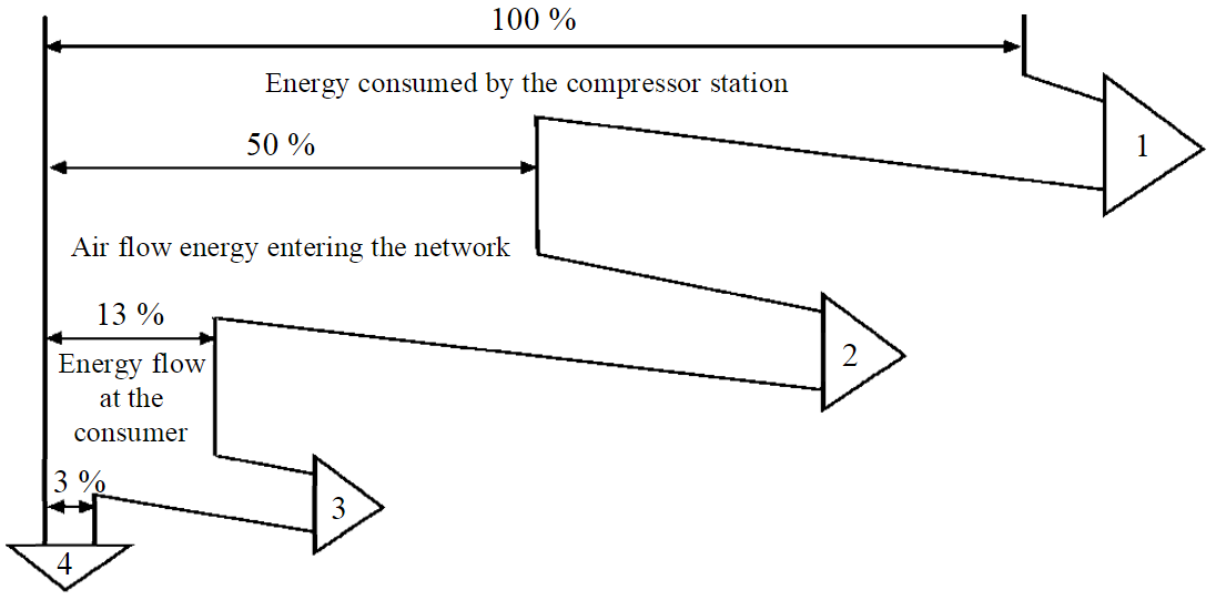
Fig.1. Energy diagram of production, distribution and consumption of compressed air at mining enterprises in Russia 1 – energy losses at the compressor station; 2 – energy losses in the air duct network; 3 – energy losses in pneumatic consumers; 4 – useful work
This level of energy loss in compressed air systems should now be considered unacceptable due to the significant impact on the production of a competitive product. Improving the energy efficiency of technological process of production and distribution of compressed air is based on modernization, technological development and the transition to the rational use of energy resources [7-10].
Opportunities to reduce energy costs for the production of compressed air are associated with a reduction in energy costs for driving compressors, transporting air through pipeline systems, and controlling pneumatic systems [11]. In papers [12, 13] it was noted that the introduction of the necessary measures for energy saving in the systems of production and transportation of compressed air has the potential to reduce energy consumption from 56 to 66 %.
The solution of the problem is carried out by complex methods. The main directions for increasing the efficiency of compressed air systems are aimed at using an electric drive with high efficiency [14], frequency-controlled drives implementation [15, 16], automatic control systems modernization [17, 18], use of modern designs of dehumidifiers and air filters [3, 19]. Consideration should be given to the external part of compressed air systems, which includes the air distribution network with shut-off and control equipment, and the process equipment itself, which have a significant impact on energy efficiency. It should be noted that some methods of compressor stations efficiency improving can lead to a deterioration in other technical indicators of the enterprise, for example, the introduction of a frequency-controlled drive negatively affects the level of power quality in terms of non-sinusoidal voltage and current [20].
Energy audit of enterprises allows to identify technical problems of compressed air systems and its distribution [21-23]. The studies note that despite the high cost of this energy carrier, the enterprises do not take into account the efficiency of the system until the pressure loss in the system reaches a critical level and begins to affect the normal course of the technological process and the normal operation of the equipment [14]. This feature of the systems leads to a temporary delay in the implementation of the necessary control actions aimed at improving the energy efficiency of production [24].
The recently promoted concept of the development of monitoring and control systems for intelligent technical complexes [7, 25] requires the development of automated systems at the enterprises of the mining industry, which would take into account the necessary factors of the life cycle of the considered technological schemes.
Methodology
A promising direction for improving energy efficiency at industrial enterprises is the introduction of high-quality energy management, which will play a significant role in maintaining the minimum electricity costs at the required level. This is achieved during the energy audit process and allows to maintain reduced energy consumption in production with savings of up to 20 % [26]. Despite the high efficiency, the implementation of energy management is constrained by the support of other priority areas by enterprises: improving the technical skills of management personnel and low motivation of employees who make the necessary decisions [27, 28].
Existing technologies make it possible to monitor the parameters of various systems of industrial facilities and visualize them on a mnemonic diagram displayed on the operator's screen. More and more mining industry enterprises are beginning to introduce modern telecommunication solutions and technologies, which can significantly reduce the likelihood of production errors and optimize the course of production processes. However, there are no available approaches for real-time monitoring of the energy performance of compressed air production and distribution systems. In many cases, the only indicator of technical or operational problems that characterize compressed air systems is the increased power consumption of the compressor station. The increase in energy consumption is influenced not only by productivity improvement of compressor installations and technical problems, but also by uncontrolled air leaks [2, 29]. Thus, it is necessary to use a system that includes real-time monitoring of key technical parameters, procedures for identifying wasted compressed air and a rapid alert system to manage the elimination of wasted air consumption cause.
Consider the technical side of improving the energy efficiency of compressed air production and distribution systems. It is customary to divide compressed air systems into two parts: production and distribution of compressed air. The first part includes the compressor units themselves, air filters, air collectors, dehumidifiers, etc. The second part includes control valves, distribution air ducts with fittings and technological equipment operating on compressed air. The second part as a whole represents the external network of the compressor unit.
Energy losses in the external network occur mainly due to air leaks, which account for up to 20-50 % of losses [3, 11]. These losses are caused by non-tightness of detachable connections, malfunction of couplings, fittings, destruction of air ducts, rupture of hoses, etc. [11].
A review of the operating experience of compressed air systems and the available opportunities to reduce energy costs in these systems allows to conclude that most technological processes have the ability to significantly reduce operating costs by reducing volumetric air leaks in external air supply networks. Repair of these systems requires minimal investment and allows to quick recoup the costs.
The key to estimating potential energy and cost savings is the amount of air flow due to leaks. Existing leak quantification methods evaluate either the total flow rate of the system or the air flow rate from individual leaks [30]. Four main methods are used to estimate total losses in a compressed air supply system, which include pressure drop testing, compressor power measurement, using a portable ultrasonic flow meter, and installing an inline flow meter. All of these methods require the interruption of production processes, since leak detection technology involves the measurement of air quantities due only to leaks in the system. Measurement of individual leaks can be performed during production. Each of the above methods has disadvantages that create a significant error in measuring air flow [31].
Another option for measuring leaks is the use of ultrasonic clamp-on flow meters, which use ultrasonic waves to estimate the speed of air flowing inside a compressed air pipeline. They directly measure the velocity in the pipe and need a known value of the pressure in the system. This method requires many settings, calibration, and also the value determination of some difficult-to-define parameters [32]. In addition, stringent requirements are imposed on the location of the flowmeter and its proper fastening to the pipe. Thus, the presence of a large number of adjustable parameters predetermines significant errors in the measurement of leakage flow.
Another method for indirectly detecting leaks is based on measuring the electrical parameters (voltage and current) supplied to the compressor motor terminals, which makes it possible to calculate the power consumed to compress air [3]. The difference between the measured and calculated compressor power makes it possible to calculate the air flow due to leaks in the system. This method is widely used in the energy audit of enterprises, but requires certification, calibration of electrical equipment and a significant investment of time to find and isolate the required electrical lines. In addition, the method is designed to estimate only the total air flow in the system and does not allow differentiating losses in individual sections of the pipeline.
When detecting individual leaks, the most common method is ultrasonic leak detection [33]. This method allowing the determination of the leaks that occur during point depressurization of pipelines, has a high error and the complexity of determining the total air flow due to the presence of many points.
Thermodynamic method using heating elements and thermocouples should be considered as a new one [31]. Leakage measurement is carried out with the process stopped, so that only the flow due to leaks circulates in the compressed air line. The compressor continues running run to maintain system pressure. The outside part of the pipe is heated by thermal heaters and the resulting temperature profile is measured using thermocouples or other similar temperature meters. When heat is supplied to a pipe, the resulting temperature profile will change depending on the air flow in the pipe. A change in air flow leads to a change in the heat transfer coefficient inside the pipe, which affects the change in temperature relative to the initial value. The method has sufficient accuracy, but requires special equipment and its appropriate calibration. The complexity and high cost of this method limits its wide application.
Discussion
The branching of the air duct network and the presence of a large number of consumers of compressed air require strict consideration of the losses that occur during the transportation of the energy carrier. Existing technical means make it possible to control the main parameters of the energy carrier at all stages of its movement. However, their widespread use is constrained by their high cost and the need for additional maintenance costs. In some cases, specialized software is required, which is used within the framework of the necessary functional tasks [34, 35]. In our opinion, under these conditions, the methods based on monitoring the main parameters of the energy carrier with a differentiated account of factors that make it possible to track leaks in real time become more appropriate. Timely localization of the detected leaks can significantly reduce harmful losses and unproductive costs in compressed air systems.
The design of compressor stations and the calculation of air duct networks for stationary compressed design operation modes of the compressed air consumers does not present great difficulties and is described in sufficient detail [36, 34]. The main task of the compressor unit is to supply air to the end consumer with the appropriate technological parameters, which include pressure, flow and air quality. Important parameters of the external network of the compressor unit are the length, diameters of pipelines, roughness, and the presence of local resistances. Appropriate calculation and subsequent selection of these parameters allows minimizing losses and using compressor machines with the lowest energy consumption.
When designing air duct networks, taking into account regulatory documents in relation to air ducts and the quality of supplied air, leakage accounting is taken declaratively from 0.3 to 0.5 m3/min per 1 km of the pipeline. The values of these design leaks are taken depending on the operating experience of compressor stations for enterprises of certain industries. This approach determines the average leakage rate without taking into account many external factors, which is rather inappropriate. Some factors can create leakage losses up to 40 % of the consumer's nominal flow [38, 39].
To ensure on time monitoring of the leakage level and its localization in the main compressed air pipelines for the purpose of subsequent management for making decisions to reduce unproductive costs, a method is proposed for indirectly determining leaks in the air pipeline network. This method consists in using the values of the air flow of consumers connected to certain areas in accordance with the scheme of the air duct network. By monitoring the pressure drop in these areas, the air flow due to leaks is determined. The method is applicable to long and branched compressed air networks, which is typical for mining and chemical industries. In such compressed air supply systems, linear pressure losses are predominant compared to local losses. Thus, using the Darcy – Weisbach equation [37], recorded for the i-th section of the air duct network, the calculated pressure drop Δpi is determined in the corresponding section, which is due to the consumption of compressed air by the consumers of this section and the leaks,
where di – pipe diameter; λ – hydraulic friction coefficient; li – reduced length of the air duct i-th section; di – diameter of air duct i-th section; Qavi – the average value of the volumetric air flow in the i-th section; ρavi – average density value of the transported compressed air.
The volumetric flow rate of compressed air in the air duct section is the sum of the flow rate of the consumer or the subsequent section and the resulting leaks, which are due to leaks in the connections and violation of the continuity of the pipeline. The average value of the volume flow can be determined from the expression
where Qui – useful volumetric flow in the i-th section, due to the consumption of end consumers; Qli – volume loss of compressed air in the i-th section.
Comparison of expressions (1) and (2) makes it possible to obtain the dependence of the pressure drop in the area under consideration on the resulting volumetric leaks in the same area:
Transformation of expression (3) makes it possible to calculate the volume leakage of compressed air in the i-th section:
The resulting expression (4) includes ρavi – the average value of the density of the transported compressed air. This parameter depends on the thermodynamic state of the transported medium. When compressed air moves from the starting point at which it has pressure parameters p1, temperature T1 and density ρ1, there is a change in its thermodynamic parameters to the values p2, T2 and ρ2. Let us take into account that the movement of compressed air through steel pipelines is accompanied by both its cooling due to heat transfer through the pipeline walls, and a certain increase in temperature due to air friction against the pipeline walls, which has a significant roughness. As a first approximation, it is assumed that the decrease in air temperature in the considered section of the pipeline occurs according to the adiabatic law. Then the average value of the density of the transported compressed air is calculated from the expression
where pbegi – absolute pressure of compressed air at the beginning of the i-th section of the pipeline; R – air gas constant; Tbegi – absolute thermodynamic air temperature at the beginning of the i-th section of the air duct.
Monitoring of compressed air parameters is carried out at key points of the air pipeline network: at the outlet of the compressor station, at the branching points of the air pipeline network, near compressed air receivers. The main prevailing parameter of compressed air for given conditions is the excess pressure at the points of the pipeline, which is recorded by digital pressure gauges and any deviation is monitored by the energy service of the enterprise. At some key points in the air supply network, digital thermometers are additionally installed, which record the temperature of the supplied compressed air. In those points of the network where there are no thermometers, the temperature is calculated by linear interpolation, from the data of the nearest points of the air duct network. According to the design scheme, pressure gauges register air pressure at the beginning p1 and at the end p2 of the sections of the observed pipeline, which allows taking into account the difference in their readings, which is equal to the total pressure drop in this section of the pipeline:
Since the volumetric performance of industrial compressors Vcom and compressed air consumers Vcon is measured in [m3/min], then moving from the dimension [m3/s] to the dimension [m3/min] and taking into account the factors not taken into account in the adopted model, we obtain the final expression for monitoring air leaks in the i-th section of the pipeline:
where Vli – estimated volumetric flow rate of leaks in the i-th section, m3/min; km – matching factor that takes into account the additional pressure drop associated with the configuration of the section of the air duct network (presence of valves, branches, turns, etc.); Vconi – estimated volumetric consumption of consumers in the i-th section, m3/min, determined according to the passport data of the equipment or the results of the last audit of the company's compressed air facilities.
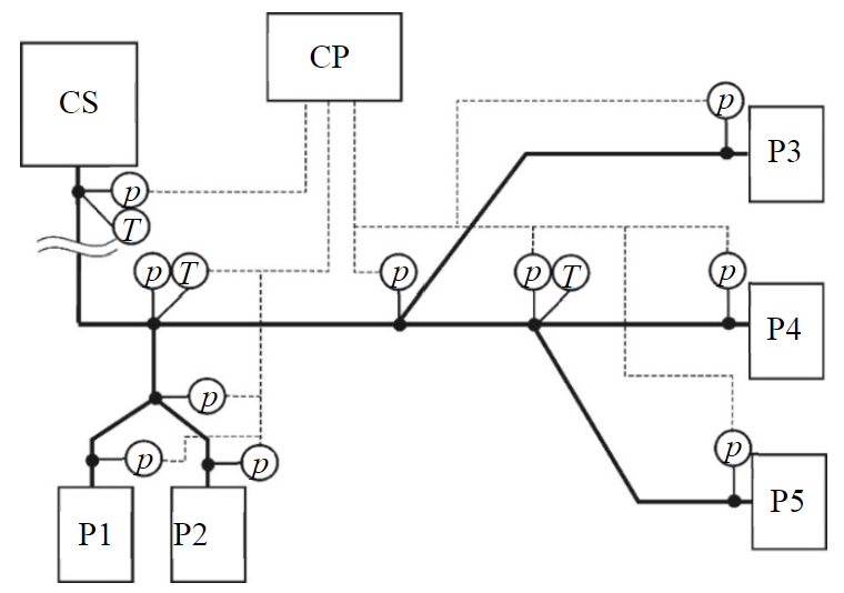
Fig.2. Approximate scheme for monitoring the air duct network of the Mir underground mine of the Mirninsky Mining and Processing Plant CS – compressor station; P1 – P5 – pneumatic receivers; p – pressure sensors; T – temperature sensor; CP – control panel
For the successful implementation of this technique, it is necessary to set the value of the matching coefficient km. Since quite a lot of random factors influence its value, the establishment of the matching coefficient value dependence on the configuration and pipeline parameters can be built on the experiment basis using empirical formulas. Experimental studies were carried out on the air duct network of the Mir mine of the Mirninsky Mining and Processing Plant of the ALROSA company. The existing mine dispatching system allows real-time monitoring of pressure readings at the control points of the compressed air pipeline and the operation of pneumatic installations. The operator of the control panel sees on the control monitor a mining plan with the location of equipment and instrument readings at control points. The functional diagram of the monitoring of the air pipeline network of the mine is shown in Fig.2. Pressure sensors are located at nodal points connecting individual sections of the air duct network, or at the locations of pneumatic receivers.
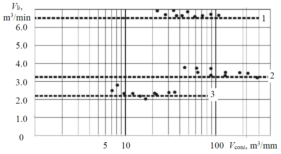
Fig.3. Results of experimental studies of the determination leaks in the sections of the air duct in the crosscut (1), in the trunk (2), in drift (3)
The need for underground and surface complexes of the Mir mine in compressed air is provided from the surface compressor station. The compressor station is equipped with four ZR-750/7.5-50 compressors (supply 124.4 m3/min, pressure (75 Pa) 7.5 kg/cm2, electric motor power 750 kW). The total design capacity of the working units is 373.5 m3/min. The operation of the compressor station is provided in automatic mode, with the output of the necessary parameters to the mine manager.
From the compressor station to the cage shaft, compressed air is supplied through a pipeline with nominal diameters of DN400 and DN350, then through the cage shaft through the DN300 pipeline, through the crosscuts of the working horizons through the DN200 pipelines, and through the rest of the workings through the pipelines with DN150 diameters. Pipelines are equipped with moisture separators and switching fittings.
Most pneumatic consumers do not have a permanent location in the mine. According to the mining plan and production needs, pneumatic consumers are connected to the compressed air pipeline in the branches provided by the project.
To calculate the loss of compressed air and the coefficient of matching km, the experimental sections were divided according to nominal diameters and location in the air supply network of the enterprise. The results of measurements of the pressure value in the studied sections of the air duct were received at the operator's console. The measurements were carried out with a different number of connected consumers of compressed air; therefore, the flow rate and the magnitude of the air pressure drop at the measurement points changed. The calculation of conditional leaks was carried out according to formula (4), while the value of the matching coefficient km was taken equal to 1. The results of measurements of leaks by experimental methods in the same sections are indicated on the graph (Fig.3) by dotted lines.
As a result of the experiments, it was found that the value of the matching coefficient is in the range from 0.93 to 0.97 (see table). At low air flow rates, the error in determining leaks by this method is reduced, which is associated with a certain sensitivity of pressure sensors and their error, which is 1-2 %. At costs corresponding to the main operating modes at the enterprise, this technique gives a satisfactory result with a measurement error of 6-7 %.
Coefficient km value
|
Area |
Nominal diameter, |
Average value |
Error of calculated |
|
Shaft |
350 |
0.93 |
5.3 |
|
Сross-heading |
200 |
0.97 |
2.5 |
|
Production sites, drifts |
150 |
0.95 |
5.8 |
The main purpose of this technique is not to accurately determine leaks, but to detect them in in-time manner and immediately localize them. The scheme of work is as follows. Instrument readings are transmitted via communication lines to the dispatcher's console, where they are visualized. The software of the automated control system for the air duct network, built taking into account the proposed methodology, allows to issue signals when the system operation mode deviates from the calculated parameters. The company's management evaluates these deviations and takes measures to localize leaks and, ultimately, to reduce the energy consumption of the company's compressor station. This system improves the energy security of compressed air transport, eliminates the influence of the human factor and is one of the steps in the development of a highly efficient digital enterprise [36, 40].
Conclusion
The results of the conducted research allow us to draw the following conclusions.
One of the methods of technical implementation of the effective management of compressed air networks is the software and hardware implementation of monitoring leaks in sections of the air-wire network, carried out in real time.
A mathematical model that takes into account the characteristics of air networks and the presence of pressure value indicators at the network control points makes it possible to determine leakages in the network by the calculation method. The results of experimental studies on the air pipeline network of the Mir mine of the Mirninsky Mining and Processing Plant showed a deviation of the calculated parameters by no more than 7 % from the actual values of leaks. The introduction of this system with a clear energy service management reduces the consumption of electrical energy of the drives of the compressor units of the Mir mine by 4720 kWh per year.
The software implementation of this method allows real-time monitoring of the air duct network state and identifying areas with increased energy losses. The method for detecting leaks in compressed air networks is characterized by simplicity, simple software integration into an existing dispatching system, and can be used to monitor the state of external networks of compressor units in industrial enterprises with an extensive air duct networks.
References
- Cabello Eras J.J., Sagastume Gutiérrez A., Sousa Santos V., Cabello Ulloa M.J. Energy management of compressed air systems. Assessing the production and use of compressed air in industry. Energy. 2020. Vol. 213. N 118662. DOI: 10.1016/j.energy.2020.118662
- Nehler T. Linking energy efficiency measures in industrial compressed air systems with non-energy benefits – a review. Renew and Sustain Energy Review. 2018. Vol. 89, p. 72-87. DOI: 10.1016/j.rser.2018.02.018
- Saidur R., Rahim N.A., Hasanuzzaman M. A review on compressed-air energy use and energy savings. Renew Sustain Energy Review. 2010. Vol. 14. Iss. 4, p. 1135-1153. DOI: 10.1016/j.rser.2009.11.013
- Mousavi S., Kara S., Kornfeld B. Energy efficiency of compressed air systems. Procedia CIRP. 2014. Vol. 15, p. 313-318. DOI: 10.1016/j.procir.2014.06.026
- Minyaev Yu.N., Ugolnikov A.V., Molodtsov V.V. Investigation of volume losses in pneumatic networks of mine compressor installations. Mining information and analytical bulletin. 2006. N 2, p. 254-257 (in Russian).
- Minyaev Yu.N. Energy losses in pneumatic systems of mining Compressor Units. Izvestiya Uralskogo gosudarstvennogo gornogo universiteta. 2003. Iss. 16, p. 44-46 (in Russian).
- Zhukovsky Yu.L., Lavrik A.Yu., Semenyuk A.V., Vasilkov O.S. Potential for Electric Consumption Management in the Conditions of an Isolated Energy System in a Remote Population. Sustainable Development of Mountain Territories. 2020. Vol. 12. N 4 (46), p. 583-591 (in Russian). DOI: 10.21177/1998-4502-2020-12-4-583-591
- Goldberg A., Reinaud J., Taylor R.P. Promotion systems and incentives for adoption of energy management systems in industry. Some international lessons learned relevant for China. 2011, p. 36.
- Harris J., Anderson J., Shafron W. Investment in energy efficiency: a survey of Australian firms. Energy Policy. 2000. Vol. 28. Iss. 12, p. 897-876. DOI: 10.1016/S0301-4215(00)00075-6
- La T. Don't Let Compressed Air Blow Away Your Profits. Energy Engineering. 2013. Vol. 111. Iss. 1, p. 7-15. DOI: 10.1080/01998595.2013.10769725
- Abdelaziz E.A., Saidur R., Mekhilef S. A review on energy saving strategies in industrial sector. Renew Sustain Energy Reviews. 2011. Vol. 15. Iss.1, p. 150-168. DOI: 10.1016/j.rser.2010.09.003
- Marshall R.C. Optimization of single-unit compressed air systems. Energy Engineering. 2012. Vol. 109. Iss. 1, p. 10-35. DOI: 10.1080/01998595.2012.1043657
- McKane A., Hasanbeigi A. Motor systems energy efficiency supply curves: A methodology for assessing the energy effi-ciency potential of industrial motor systems. Energy Policy. 2011. Vol. 39. Iss. 10, p. 6595-6607. DOI: 10.1016/j.enpol.2011.08.004
- Kaya D., Phelan P., Chau D., Sarac H.I. Energy conservation in compressed-air systems. International journal of Energy Research. 2002. Vol. 26. Iss. 9, p. 837-849. DOI: 10.1002/er.823
- Shkliarsky Y.E., Bragin A.A. Reducing Power Losses in Electric Networks of Enterprises. Izvestiya vysshikh uchebnykh zavedenii. Gornyi zhurnal. 2013. N 1, p. 99-103 (in Russian).
- Abd Elsadek E.M., Ashour H., Refaat R.A., Mostafa M. Efficiency Improvement and Saving Energy within Electro-Pneumatic System Using VFD: (case study: Production line). Proceedings of 2019 International Conference on Innovative Trends in Computer Engineering (ITCE 2019), 2-4 February 2019, Aswan, Egypt. IEEE, 2019, p. 248-253. DOI: 10.1109/ITCE.2019.8646536
- Neale J.R. , Kamp P.J.J. Compressed air system best practice programmes: What needs to change to secure long-term energy savings for New Zealand? Energy Policy. 2009. Vol. 37. Iss. 9, p. 3400-3408. DOI: 10.1016/j.enpol.2009.04.047
- Gordon F., Peters J., Harris J., Scales B. Why is the treasure still buried? Breaching the barriers to compressed air system efficiency. Proceedings ACEEE Summer Study on Energy Efficiency in Industry. 1999, p. 709-718.
- Terrell R.E. Improving compressed air system efficiency – know what you really need. Energy Engineering: Journal of the Association of Energy Engineering. 1999. Vol. 96. Iss.1, p. 7-15. DOI: 10.1080/01998595.1999.10530444
- Pirog S., Shklyarskiy Y.E., Skamyin A.N. Non-linear Electrical Load Location Identification. Journal of Mining Institute. 2019. Vol. 237, p. 317-321. DOI: 10.31897/PMI.2019.3.317
- Hasmandova M. Compressed air systems: Auditing and replacing air compressors. Filtration & Separation. 2008. Vol. 45. Iss. 9, p. 41-42. DOI: 10.1016/s0015-1882(08)70373-2
- Thabet M., Sanders D., Haddad M. et al. Management of Compressed Air to Reduce Energy Consumption Using Intelligent Systems. Advances in Intelligent Systems and Computing, 3-4 September 2020, London, United Kingdom. Springer, 2020. Vol. 1252, p. 206-217. DOI: 10.1007/978-3-030-55190-2_16
- Trianni A., Accordini D., Cagno E. Identification and categorization of factors affecting the adoption of energy efficiency measures within compressed air systems. Energies. 2020. Vol. 13. Iss. 19. N 5116. DOI: 10.3390/en13195116
- Dindorf R. Estimating potential energy savings in compressed air systems. Procedia Engineering. 2012. Vol. 39, p. 204-211. DOI: 10.1016/j.proeng.2012.07.026
- Palyanicin P.S., Petrov P.A., Bazhin V.Yu. Issues of resource and energy saving in corundum production. iPolytech Journal. 2020. Vol. 24. N 6, p. 1347-1356 (in Russian). DOI: 10.21285/1814-3520-2020-6-1347-1356
- May G., Stahl B., Taisch M., Kiritsis D. Energy management in manufacturing: From literature review to a conceptual framework. Journal of Cleaner Production. 2017. Vol. 167, p. 1464-1489. DOI: 10.1016/j.jclepro.2016.10.191
- Brunke J.C., Johansson M., Thollander P. Empirical investigation of barriers and drivers to the adoption of energy conser-vation measures, energy management practices and energy services in the Swedish iron and steel industry. Journal of cleaner pro-duction. 2014. Vol. 84, p. 509-525. DOI: 10.1016/j.jclepro.2014.04.078
- Fernando Y., Wei Lin Hor. Impacts of energy management practices on energy efficiency and carbon emissions reduction: A survey of Malaysian manufacturing firms. Resources, Conservation and Recycling. 2017. Vol. 126, p. 62-73. DOI: 10.1016/j.resconrec.2017.07.023
- Nehler T., Parra R., Thollander P. Implementation of energy efficiency measures in compressed air systems: barriers, drivers and non-energy benefits. Energy Efficiency. 2018. Vol. 11, p.1281-1302. DOI: 10.1007/s12053-018-9647-3
- Perz K., Rewolińska A. Impact of network expansions on energy losses in compressed air. 1st International Conference Functional and Engineering Materials – FEM 2019 16-18 October 2019, Lodz, Poland. IOP Conference Series: Materials Science and Engineering. 2020. Vol. 743. N 012045. DOI: 10.1088/1757-899X/743/1/012045
- Terrill T.J., Kim T., Rasmussen B.P. Feasibility of using thermal response methods for nonintrusive compressed air flow measurement. Flow Measurement and Instrumentation. 2021. Vol. 77. N 101869. DOI: 10.1016/j.flowmeasinst.2020.101869
- Belligoli Z., Dwight R., Kok G., Lucas P. A Bayesian study of uncertainty in ultrasonic flow meters under non-ideal flow conditions. Metrologia. 2017. Vol. 54. Iss. 4. N 584. DOI: 10.1088/1681-7575/aa7b8d
- Guenther T., Krol A. Automated detection of compressed air leaks using a scanning ultrasonic sensor system. 2016 IEEE Sensors Applications Symposium (SAS), 20-22 April 2016, Catania, Italy. IEEE, 2016. N 16051876. DOI: 10.1109/SAS.2016.7479830
- Emelyanov A.P., Vasilyev B.Yu. Algorithms and Technical Control Means of Automatic Electric Drive of Turbomachines. Vestnik of Ivanovo State Power Engineering University. 2013. N 1, p. 92-96 (in Russian).
- Ilyushin Y.V., Afanaseva O.V. Development of Scada-model for trunk gas pipeline’s compressor station. Journal of Mining Institute. 2019. Vol. 240, p. 686-693. DOI: 10.31897/PMI.2019.6.686
- Koteleva N.I., Zukovsky Y.L., Kozak R.A. Augmented Reality Technology as a Method of Increasing the Safety of Industrial Production. Mining informational and analytical bulletin. 2019. N S7, p. 117-129 (in Russian). DOI: 10.25018/0236-1493-2019-4-7-117-129
- Menon E.S. Piping Calculations Manual. NY: McGraw-Hill Education, 2005, p. 666.
- Kuznetsov Yu.V., Kuznetsov M.Yu. Compressed air. Ekaterinburg: Uralskoe otdelenie Rossiiskoi akademii nauk, 2007, p. 511 (in Russian).
- Menon E.S. Pipeline Planning and Construction Field Manual. Elsevier Inc, 2011, p. 576.
- Lisovsky V.V., Rodionov V.A. The main directions of improvement of the unified system of management of industrial safety and labor protection in JSC “SUEK”. Mining informational and analytical bulletin. 2019. N S6, p. 21-32 (in Russian). DOI: 10.25018/0236-1493-2019-4-6-21-32