
Development of the concept of an innovative laboratory installation for the study of dust-forming surfaces
- 1 — Ph.D. associate professor Saint Petersburg Mining University ▪ Orcid ▪ Elibrary ▪ Scopus ▪ ResearcherID
- 2 — Ph.D. associate professor Saint Petersburg Mining University ▪ Orcid ▪ Elibrary ▪ Scopus ▪ ResearcherID
- 3 — Ph.D. associate professor Saint Petersburg Mining University ▪ Orcid ▪ Elibrary ▪ Scopus ▪ ResearcherID

Abstract
Currently, the determination of the emission rate of suspended solids from a unit of the surface area of a man-made mass at various parameters of the wind flow is not sufficiently described. The analysis of the world experience of researchers shows that existing laboratory installations have various design features that do not allow to correctly determine the mass of the dust being flapped and wind-blown. Based on the analysis results, the concept of an innovative laboratory installation for the study of dust-forming surfaces has been developed. It takes into account the influence of wind shadows, the deturbulization of an artificially created air flow, the possibility of regulating not only the flow velocity mode, but also the creation of a vacuum or disturbance in the area of sample placement, as well as the formation of a certain angle of wind flow attack relative to the surface. The concept provides for the possibility of determining the volume of dust emissions by the values of the lost dust masses in the sample and by the values of dust concentrations in the outgoing stream. The calculation of the main basic elements of the installation using the ANSYS FLUENT software package was carried out. The model and configuration of the wind tunnel have been developed and calculated, the main geometric parameters and functional elements for the possibility of use in scientific work have been determined. For practical use of the empirical roughness value of the underlying surface, its values are recommended in a wide range – from zero for the water surface to 0.44 for large cities with tall buildings and skyscrapers.
None
Introduction
The problem of atmospheric air pollution by suspended solids is extremely relevant in mining, processing, construction and many other industries where loose media are used. The existing means of measuring dust concentrations make it possible to analyze the current state of the air environment, certain types of measuring equipment perform operational data processing to obtain graphs of changes in concentrations and separation of dust into particles. Nevertheless, the issue of determining the masses of flapped and wind-blown dust remains open for conducting a detailed inventory of sources of atmospheric air pollution and design calculations of the negative impact of industrial facilities. The existing methods for calculating the volume of emissions of pollutants are based on taking into account a number of coefficients and often give a significant discrepancy with the monitoring data.
The actual mass of dust transfer from its source to the considered point of the airspace or surface depends on a number of environmental factors. The main ones include: the mode of wind flow action, air humidity, particle size and chemical composition, hygroscopicity of dust, structure and shape of dust particles, air temperature and dust particles, etc. Correct calculation methods for determining the actual values of dust transfer masses are not currently being developed due to the high complexity of accounting for all conditions and large values of errors in the calculation.
The Mining University has repeatedly considered the issue of dust pollution of the atmosphere in the areas where enterprises of the mineral resource complex are located [16, 19] and the problem of determining the volume of dust transfer from the source to the settlement point was raised [6, 11]. Work on the creation of complexes that allow laboratory assessment of environments under wind load was carried out by specialists of the Mining University [8, 12, 13] and specialists of other organizations, but the main problem of the used installations was the lack of possibility of creating conditions close to atmospheric [2, 28]. The developed concept of an innovative laboratory installation for the study of dusty surfaces, taking into account the influence of aerodynamic shadows, the deturbulization of artificially created air flow, the possibility of regulating not only the flow velocity, creating a vacuum or disturbance in the area of sample placement, as well as the formation of a certain angle of wind flow attack relative to the surface, is an important scientific and practical task [3, 4, 25].
The research purpose is to develop the concept of an innovative laboratory installation for the study of dust-forming surfaces, which can be effectively used to solve practical problems of determining the dust discharge from man-made objects. This allows to spot-fix the negative effects of dust-forming objects, as well as effectively prevent them.
The research task is to simulate the velocity field of the air flow in the tunnel using various design solutions, taking into account the conditions of the laboratory room and a wide range of dust emission conditions under study.
Methodology
The project was implemented on the basis of the laboratory, experimental and stock base of the Scientific and Educational Center of the Mining University using the equipment of the Center for Collective Use of the Mining University.
The laboratory installation used includes:
- The dust suppression hopper BPP 001 is a sealed demountable device with transparent walls for monitoring the process of dust blowing, with sealed holes for connecting measuring equipment and installing air blowers.
- UETM EP-2 air blower for creating a directional air flow in the hopper space and aerodynamic impact on the test sample.
- Combined semi-automatic dust meter DustTrak 8533 for measuring the mass concentration of dust particles PM1.0, PM2.5 and PM10 by laser-nephelometric method.
- Meteorological meter MES-200A for assessing the microclimatic parameters of the environment.
The air flow simulation was carried out by the finite element method in the Ansys Fluent environment. Ansys Fluent is an Ansys module for CFD analysis designed for modeling hydro-gas dynamic processes (flow of liquids and gases, turbulence, combustion, heat exchange, etc.).
The work took into account the current legal acts regulating the sphere of environmental safety, as well as labor protection of workers and residents of settlements in the zone of influence of polluting objects.
Discussion
The installation for the study of dust-forming surfaces developed at Shandong University of Science and Technology and Liaoning Technical University is considered (Fig.1).
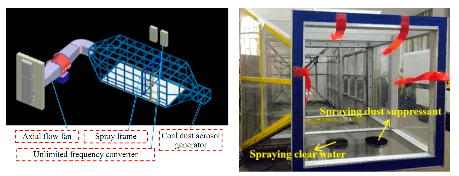
Fig.1. Dusting Media Testing Facility of Shandong University of Science and Technology and Liaoning Technical University (China) [9, 20, 26]
The laboratory installation – the dust suppression hopper BPP 001, which provides the tasks of determining the effectiveness of dust suppression means, is used at the Mining University (Fig.2). Aerodynamic installations always allow a discrepancy, but low wind loads increase this discrepancy, which was confirmed by the research of MK-130.2020.5 (Mining University). Despite the possible use of these complexes to determine the effectiveness of the developed means of dust suppression, they do not allow creating conditions similar to atmospheric ones due to structural aerodynamic features [21, 22, 24]. Determination of the dust transfer masses is possible only by fixing the concentrations at the outlet of the installation, which places increased demands on the aerodynamic design of such stands.
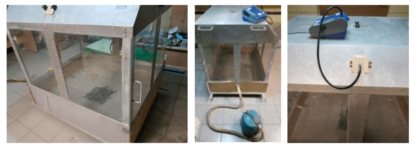
Fig.2. Dust suppression hopper BPP 001 (Mining University)
The variability of the cross-sections of the flow part, the presence of zones of wind shadows, turbulence created by bends and turns of the flow part, the walls of the flow part have a significant impact on the velocity fields. The dust suppression hopper is made in the form of a parallelepiped, which implies the presence of dihedral and triangular sharp corners inside the installation. Corners are zones of wind shadows, the presence of which can lead to a partial accumulation of the blown test material, and then give a secondary concentration during the experiment.
The test site is located at the bottom of the hopper, there is no possibility of excluding the influence of the surface. In full-scale conditions, the influence of the earth surface on wind velocity is possible, but it will be varying under different conditions of surface roughness. In a laboratory installation, it should be possible to lift the test site above the surface to minimize its influence. The hopper does not have an air outlet. However, the installation is not sealed, the air is discharged through felt wipers between the collapsible elements of the installation. The cross-sectional area of felt wipers is large and the air outlet velocity through them is extremely small, but the possibility of the aerosol filtration process in felt is not excluded.
The placement of samples on the bottom of the hopper does not allow determining the final mass of samples, which in fact does not make it possible to determine the effectiveness of fixing means only by the values of concentrations in the air of the hopper. The use of an isolated installation in any case implies the presence of the influence of the walls on the air propagation. The exclusion of influence is achieved by creating an open working part. On the other hand, the creation of an open working part will lead to the loss the part of the dust during spraying and it will be impossible to determine the effectiveness of the fixing means by concentration.
The artificially created air flow does not always correspond to the real wind in terms of the degree of turbulence, especially if the flow is created by an electric fan, which necessitates the use of deturbulating devices. Within the regulatory framework of Russia, at the design stage, the calculation of concentration fields can be made only on the basis of the MRR-2017 methodology, which operates with the main characteristic – the intensity of the source emission calculated by various industry methods. Determining the intensity of emissions experimentally is a key task that a new aerodynamic installation should solve.
Taking into account the research of the Mining University, Shandong University of Science and Technology and Liaoning Technical University, the requirements for a new aerodynamic installation were formulated:
- the use of a constant section of aerodynamically correct shape as the flow part of the tunnel;
- an open tunnel contour for the possibility of eliminating dust pulling into the working part repeatedly;
- the ability to estimate the mass of blown dust, as well as the concentrations of blown dust at the outlet;
- testing of samples in the open working part to exclude the influence of walls on the air velocity field;
- availability of devices for deturbulization of artificially created air flow;
- constructive possibility of modeling different variants of the type of the wind flow movement due to discharge, backup, with the formation of a disturbance zone, etc.
One of the most aerodynamically correct cross-sections is round, but to ensure similarity, the cross-section should have the largest possible diameter. Often fans and air blowers have a smaller cross-section and use a cone-shaped socket at the outlet. In the conditions of conducting experiments in the laboratories of the university, there are limitations on the device dimensions, therefore, the tunnel section in consideration is selected from the standard row – 500 mm. Numerical simulation of air flows by the finite element method allows to minimize experimental studies. In [23], the authors investigated the effect of wind load on moving objects, in [17] – the formation of ripples in the sand under the influence of air flow, modeling the intensity of dust propagation in the mine at different flow velocities was carried out in [10].
At the first stage, the influence of a cone-shaped socket on the distribution of air velocities and turbulence was studied. The transition from a supply pipe with a diameter of 100 mm to a tunnel with a diameter of 500 mm, the estimated tunnel section with a length of 5 diameters (2500 mm) is considered (Fig.3). Initial and boundary conditions: air inflow through a pipe with a diameter of 100 mm at a velocity of 93.75 m/s (based on the reduction of the average velocity to 15 m/s in a pipe with a diameter of 500 mm), air temperature 20 °C, relative humidity 45 %, roughness value of all surfaces 0.2.
It can be seen from Fig.3, a that with the coaxial placement of the supply pipe and the tunnel after the cone-shaped socket, the flow calms down only at a distance of about four diameters, while a relatively uniform velocity field is observed in the output section. The calculation and the results of which are presented in Fig.3, b, is aimed at determining the possibility of using a 180° rotation to increase the length of a small-section pipe while reducing the dimensions of the installation. Increasing the length of the small-section pipe is necessary to ensure better flow equalization before entering the cone. The calculation showed that even with elongation, the presence of rotation does not provide equalization and there is a displacement of the flow to one of the walls. The calculation of models with smaller tunnel lengths and cone-shaped socket angles showed a similar result. The coaxial placement of the supply pipe and the tunnel was chosen, but with the elimination of the cone-shaped socket in the installation, i.e. the use of a constant tunnel section.
Fig.3. Estimation of the velocity field in the tunnel when using a small-section air blower and a cone-shaped socket with direct air supply (a) and when air is supplied through a 180° turn (b)
Flow equalization in the case of application of coaxial placement of the feed pipe and tunnel is achieved at a distance of about five diameters, which confirms the well-known rule of hydraulics about the distance of equalization of the velocity field. The next stage of the work was a model study of constant cross-section tunnel (500 mm) using an air blower (fan) of the corresponding cross-section. Based on the experience of creating wind tunnels for other industries, it was decided to consider not only the operation of the air blower for inflow (Fig.4, a), but also for air extraction (Fig.4, b). Initial and boundary conditions: air inflow and extraction using a simulated axial fan with an average cross-section velocity of 15 m/s, air temperature of 20 °C, relative humidity of 45 %, roughness value of all surfaces 0.2.
Fig.4. Estimation of the velocity field in a tunnel of constant cross-section when the air blower is operating on the air flow into the tunnel (a) and on the extractor (b)
According to the simulation results, it can be seen that the velocity field is stabilized worse when the fan is working on the air supply than when the fan is working on the extractor, so the second option is more preferable. But the use of two fans will make it possible to simulate the conditions of disturbance or discharge in the air, which gives additional opportunities when conducting laboratory studies of dust-forming surfaces in the installation. The use of a single fan in a tunnel with a closed air circulation will not allow such an effect. Closed circulation when working with dust-forming media always implies secondary intake of dust and the impossibility of minimizing the background concentration in the supplied air, therefore, the use of an open design is preferable.
When modeling environmental conditions, the most important is the field of air velocities formed in the area of the test samples placement. A velocity field close to the normal one is not reached directly in a tunnel with a diameter of 500 mm, this is caused by the small diameter of the tunnel, which is due to a decrease in the overall dimensions of the device for its placement in the laboratory room. This necessitates to make a tear in the working part of the tunnel, as is done in wind tunnels for testing flight equipment. At the next stage of the research, the velocity field in the open part of the wind tunnel was evaluated. At the beginning, the calculation was carried out under the condition of air extraction from the tunnel and the free working part (Fig.5, a) and air discharge and the free working part (Fig.5, b). When air is extracted, it can be seen that at the specified initial velocities, the exit velocities from the working part are concentrated and the velocity increases significantly only at a distance of 0.1 diameter from the inlet, which does not allow obtaining the desired field in the working part, while when air is injected at the exit to the working part, a flare is formed with almost complete preservation of flow parameters at a distance of up to two diameters. When using an intake fan, an outlet pipe, a closed working part, a table for placing samples (Fig.5, c), it is possible to observe the formation of disturbances in the working part, while a similar design, but with the fan working on the extractor (Fig.5, d), shows the uniformity of the velocity field. In the presence of two fans – inlet and extract (Fig.5, e), the velocity field is extremely close to the field in the presence of only an extractor fan. Initial and boundary conditions: air extraction using a simulated axial fan with an average cross-section velocity of 15 m/s, air temperature of 20 °C, relative humidity of 45 %, roughness value of all surfaces 0.2. The open working part is square in cross-section with a side size of 2500 mm.
Therefore, it was decided to focus on the layout with an extractor fan, but with the preservation of the intake fan to create a backup and a disturbance zone. The result of the work was an innovative laboratory installation for the study of dust-forming surfaces (Fig.6). Before using the laboratory installation, one of two wind tunnel configurations is chosen – a tunnel with an open part in the sample placement area is used (Fig.6, a), if it is necessary to simulate the conditions of exposure to wind flow in an open area without the influence of the tunnel walls, or the air supply pipe 5 and the air extraction pipe 12 are hermetically joined and form a closed tunnel (Fig.6, b) with isolated sample placement, in which there is no loss of dust-forming component during operation, and the impact assessment on the samples under study can be carried out by concentration values.
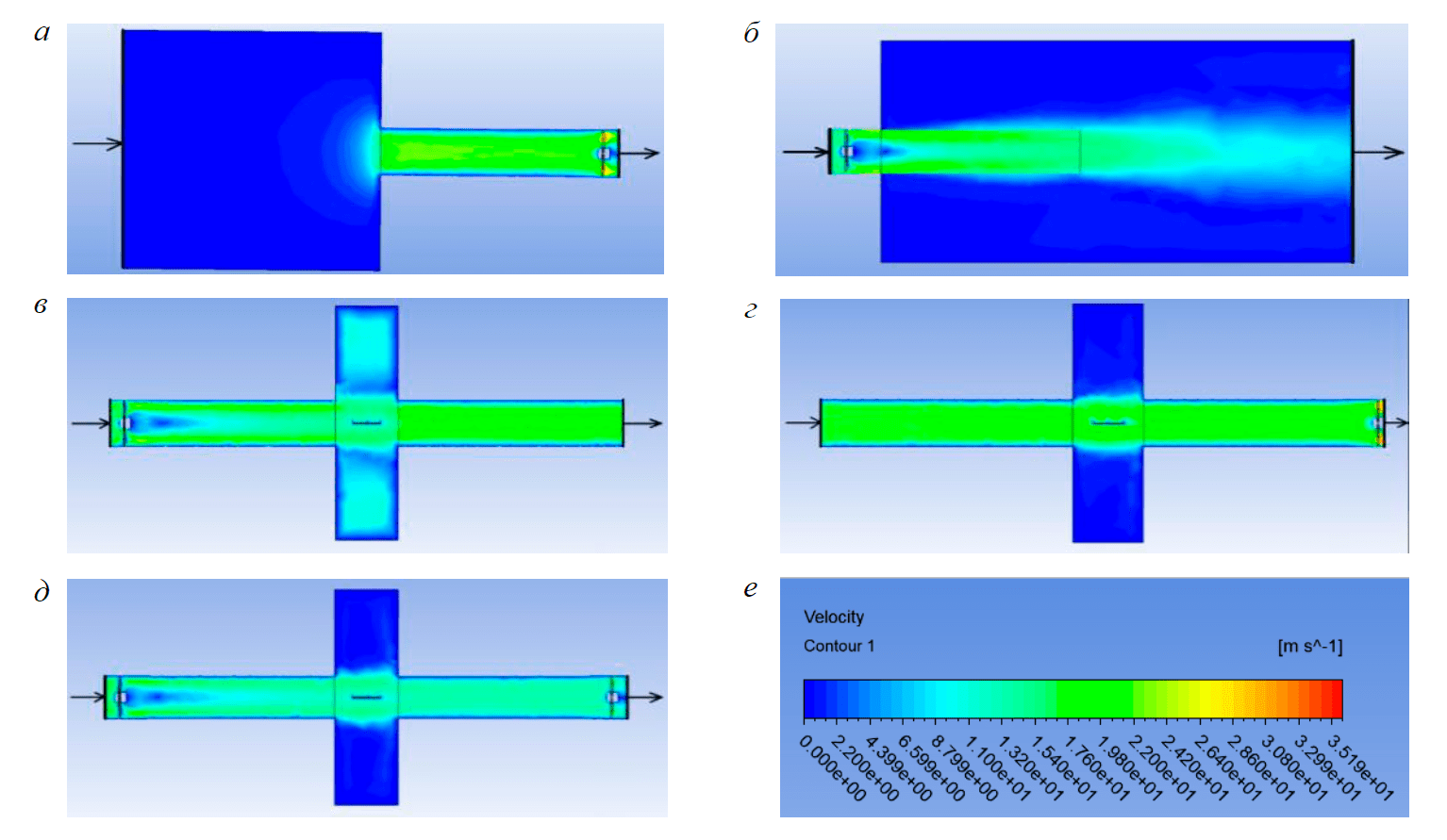
Fig.5. Estimation of the velocity field in a tunnel with a tear in the working area when air is supplied at a velocity of 15 m/s when using: а– an extractor air blower and a free working part; b – intake air blower and free working part;c – intake air blower and outlet pipe in the presence of a table for placing samples; d – extractor air blower and inlet pipe in the presence of a table for placing samples; e – intake and extractor air blowers in the presence of a table for placing samples; f – air velocity scale
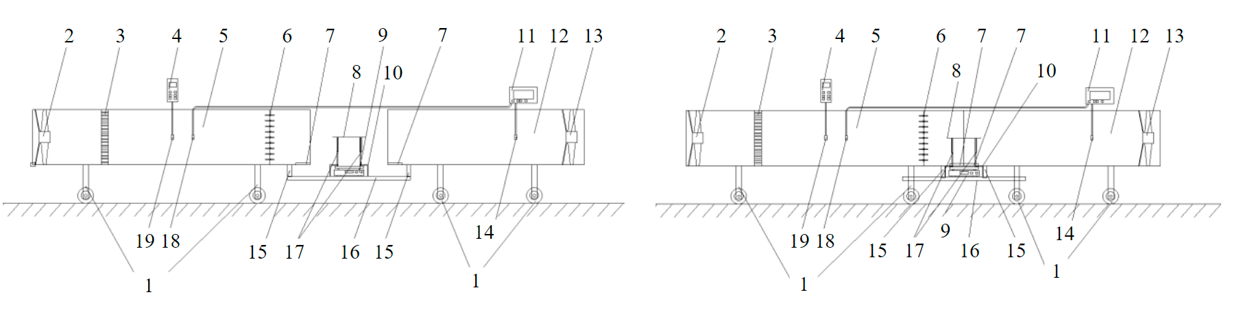
Fig.6. Laboratory installation – wind tunnel for the study of dust-forming surfaces 1 – wheel supports with a stopper; 2 – removable intake fan; 3 – deturbulating grids; 4 – meteorological meter; 5 – air supply pipe; 6 – removable adjustable deflectors; 7 – sealed slots; 8 – sample testing table; 9 – scale; 10 – clamps; 11 – dust meter; 12 – air extraction pipe; 13 – extractor fan; 14 – sampling device of the measured dust; 15 – guides; 16 – frame; 17 – adjustable supports; 18 – background dust sampling device; 19 – measuring probe
By pre-regulating the operation of the removable intake fan 2 (or removing it) and the extractor fan 13, the aerodynamic mode is adjusted – modeling the conditions of disturbance or discharge in the wind flow and setting a certain flow velocity, as well as determining other microclimatic parameters with a meteorological meter 4 through a measuring probe 19. At the same time, the unevenness in the near field of wind velocities of the removable intake fan 2 (which the extractor fan 13 does not possess) is compensated by the deturbulating grids 3 installed behind it, and the removable adjustable deflectors 6 can be the angle of the wind direction relative to the surface of the sample testing table 8.
The sample testing table 8, supported by a scale 9, is set to the required height by adjustable supports 17, while remaining unloaded and blocked by clamps 10. After setting the aerodynamic mode, the operation of fans 2 and 13 is suspended. The clamps 10 are disconnected, the scale 9 is calibrated. A sample of the tested dust-forming component is placed on the surface of the table 8, after which it is weighed with a scale 9. Then, with clamps 10, the table 8 is fixed immobile.
In the case of using a wind tunnel configuration to study dust-forming surfaces with an open part in the sample placement area (Fig.6, a), the air supply pipe 5 and the air extraction pipe 12 are fixed at a given distance by wheel supports with a stopper 1. When using a wind tunnel configuration with isolated placement of samples (Fig.6, b), when the air supply pipe 5 and the air extraction pipe 12 are hermetically joined, the table for test samples 8 on adjustable supports 17 is pushed into the tunnel through sealed slots 7. Next, either both fans 2 and 13 are started, or one of them according to the selected aerodynamic mode.
During a certain exposure time, the dust meter 11 measures the background dust concentration by the background dust sampling device 18 and the dust concentration in the polluted air stream by the measured dust sampling device 14. After the fans 2 and 13 stop working, the clamps 10 are disconnected and the scale 9 measures the mass of the sample of the tested dust-forming component after aerodynamic impact on it.
The comparative characteristics of the dust media testing facility developed by Shandong University of Science and Technology and Liaoning Technical University (China) and the developed wind tunnel for the study of dust-forming surfaces are presented in the table.
Comparative characteristics of the dust media testing facility and wind tunnel for the study of dust-forming surfaces
|
Dust media testing facility (China) |
Wind tunnel for the study of dust-forming surfaces |
|
An indirect pipe of non-constant square cross-section with wind shadows in two-sided and three-sided corners is used as a flow part |
A straight pipe of constant cross-section with an aerodynamically correct round shape is used as a flow part. |
|
Testing of samples is possible only in a closed pipe with the placement of samples isolated from the supplying air with the determination of the intensity of dust emission only by mass loss |
Testing of samples is possible both in a closed pipe with sample placement isolated from the supplying air (determination of dust emission intensity by mass loss and concentrations), and with an open working part in the sample placement area to exclude the influence of walls on the air velocity field (determination of dust emission intensity by mass loss) |
|
There are no flow deturbulization devices |
There is a deturbulating grid of artificially created air flow |
|
There are no devices for varying the angle of the wind direction relative to the test surface |
There are removable adjustable deflectors for adjusting the angle of the wind direction relative to the surface of the sample testing table |
|
There is no constructive possibility of modeling various conditions for creating a wind flow |
Due to the use of a removable intake fan, it is possible to simulate the wind flow due to discharge, backup, with the formation of a disturbance zone, etc. |
|
Analysis of the mass of samples before and after aerodynamic impact is possible only with the discharge of samples from the installation |
Mass analysis of samples is possible immediately after testing directly in the installation by placing a table on a scale with clamps and sealing |
The issue of considering the wind velocity field above the surface deserves special attention. The flow of air in the atmospheric layer up to 500 m is significantly influenced by the relief of the underlying surface and the presence of buildings, which are considered on the scale of currents as a conditional roughness of the friction surface. According to experimental data on the profile of wind velocities in the surface layer, a logarithmic pattern is derived (Fig.7). On the earth surface, due to the well-known hydro- and aerodynamic conditions of complete adhesion, both the normal and two tangential components of the velocity turn to zero:
where V1– wind velocity at a given height, m/s; V0 – wind velocity at a known height, m/s; H1 – given height, m; H0 – known height of wind velocity determination, m; k – the empirical roughness value of the underlying surface varies from zero for the water surface to 0.44 for large cities with tall buildings and skyscrapers.
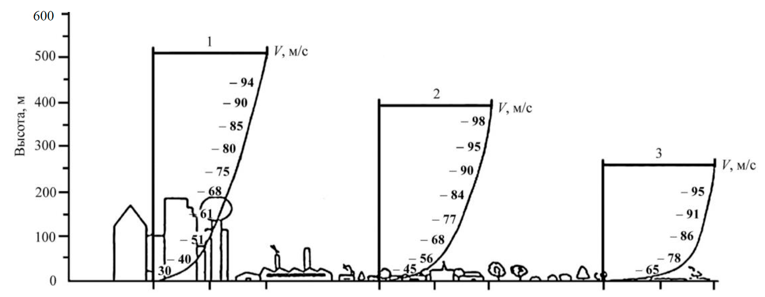
Fig.7. Examples of the influence of conditional roughness of the terrain surface on the wind velocity profile 1 – city; 2 – suburb; 3 – flat terrain (outside the city)
An individual question raises the accepted value of k. In many works, k = 0.143 is accepted, sometimes it is recommended to take k = 0.2. In the calculation methods of the USA, values from 0.2 to 0.26 are used for various places. When measured at different heights, the k values reach 0.34. In some works for Ukraine, k = 0.167 is used. Specialists of the design and Engineering Technology Bureau "CONCORD" (Ukraine) proposed the following values: water surface – k = 0; fully open landscape with a soft surface such as runways at airports, mown grass, etc. – k = 0.12; open agricultural land with single buildings – k = 0.245; agricultural land with separate buildings and eight–meter fences at a distance of more than 1250 m – k = 0.275; more than 500 m – k = 0.30; agricultural land with groups of buildings and eight–meter fences at a distance of more than 250 m – k = 0.335; villages, small towns, agricultural lands with separate buildings and high fences, forests and sharply rugged terrain – k = 0.37; large cities with tall buildings – k = 0.405; very large cities with tall buildings and skyscrapers – k= 0.44. The use of dependence with the choice of criterion k for the territory under consideration will make it possible to search for a similarity criterion when using the results of the experiment in practice during design. Understanding the regularity will allow extrapolation of wind velocity conditions when using the results of laboratory studies in a wind tunnel in practice.
Thus, a wind tunnel for the study of dust-forming surfaces has an aerodynamically correct shape of a constant circular cross-section without the possibility of forming stagnant zones and allows to simulate the process of wind action on a dust-forming surface when placing a table for test samples in open air conditions close to real, in conditions of a closed tunnel and isolated placement of samples without loss of the dust-forming component. In this case, the dust discharge can be determined both by the concentration field formed in the tunnel after the table, and by the loss of mass of the tested dust-forming component. The presence of an intake fan, in addition to the extractor fan, allows to simulate the conditions of disturbance or discharge and set a certain flow velocity. The use of deturbulating grids makes it possible to equalize the field of wind velocities, and removable adjustable deflectors – to simulate the wind direction non-parallel to the surface.
Prospective areas of research: continuation of the study of the air flow velocities influence in the tunnel, determined by a meteorological meter, and wind at a standard height of 10 m or any other height within 500 m from the surface of a dust-forming man-made massif, taking into account natural and anthropogenic relief elements; for practical use of the empirical roughness index of the underlying surface, continuation of studies aimed at clarifying the values of this indicator.
Conclusion
Despite the development of methods for the dispersion of pollutants, their use for the assessment of dust pollution of the atmosphere often does not allow to obtain a result that meets the real monitoring data. The reason for this is the imperfection of complexes and methods for estimating dust transfer masses. The developed complex represents a new concept of an aerodynamic installation for testing dust-forming surfaces, solving the problem of similarity of model conditions of dust distribution to real ones. The authors have developed the concept of an innovative laboratory installation for the study of dust-forming surfaces. Velocity fields were constructed and analyzed using various design solutions, which were selected based on the conditions of the laboratory and the formulated requirements for the laboratory installation.
An installation is recommended that can be effectively used to solve practical problems [5, 27], namely, determining the dust discharge from man-made objects. This makes it possible to spot-fix the negative effects of dust-forming objects and effectively prevent them [18]. Due to the lack of a high-quality methodological and equipment base for the study of dust suppression methods, the frequent use of these methods does not lead to the expected result, and confirmation of effectiveness can be provided only after implementation. The developed complex, in addition to determining the dust discharge, can be used to study the dust suppression means and determine the effectiveness of their use.
The developed complex will make it possible to simulate aerodynamic effects in two modes: in the closed tunnel mode, which will bring the test conditions closer to the conditions created by other installations of this type, which will provide similarity for comparing the results with the results of other studies; in the open working part mode, in which the conditions are close to real atmospheric conditions.
The use of the above formula will make it possible to interpret the air flow velocity in the tunnel, determined by the meteorological meter, into wind velocity at any height within 500 m from the dust-forming surface, taking into account natural and anthropogenic relief elements.
The developed laboratory installation can be used in scientific research, environmental monitoring, research conducted under economic agreements [1, 3, 29], in particular in the context of sustainable development [14, 15]. The results can be used in the educational process in laboratory work devoted to the study of dust-forming processes.
References
- Zhukovskij Yu.L., Sizyakova E.V. The introduction of the system of energy saving and energy efficiency at the enterprises of metallurgy. Journal of Mining Institute. 2013. Vol. 202, p. 155-160 (in Russian).
- Kovshov S.V., Gridina E.B., Ivanov V.V. Installation for modeling the process of dust suppression in open-pit mines by wetting. Water and Ecology. 2018. N 3 (75), p. 68-75. DOI: 10.23968/2305-3488.2018.20.3.68-75 (in Russian).
- Lyashenko V.I., Golik V.I., Dyatchin V.Z. Increasing environmental safety by reducing technogenic load in mining regions. Izvestiya. Ferrous Metallurgy. 2020. Vol. 63. N 7, p. 529-538. DOI: 10.17073/0368-0797-2020-7-529-538 (in Russian).
- Lyashenko V.I., Golik V.I., Dyatchin V.Z. Storage of tailings in the form of a hardened mass in underground mined-out spaces and tailings facilities. Obogashchenie rud. 2020. N 1, p. 41-47. DOI: 10.17580/or.2020.01.08 (in Russian).
- Kazakov B.P., Levin L.Y., Shalimov A.V., Zaitsev A.V. Development of energy-saving technologies providing comfortable microclimate conditions for mining. Journal of Mining Institute. 2017. Vol. 223, p. 116-124. DOI: 10.18454/PMI.2017.1.116
- Alekseenko A.V., Pashkevich M.A. Novorossiysk agglomeration landscapes and cement production: Geochemical impact assessment. XX International Scientific Symposium of Students, Postgraduates and Young Scientists on “Problems of Geology and Subsurface Development”, 4-8 April 2016, Tomsk, Russia. IOP Conference Series: Earth and Environmental Science, 2016. Vol. 43. N 012050.DOI: 10.1088/1755-1315/43/1/012050
- Bykowa E., Hełdak M., Sishchuk J. Cadastral land value modelling based on zoning by prestige: A case study of a resort town. Sustainability. 2020. Vol. 12. Iss. 19. N 7904. DOI: 10.3390/SU12197904
- Danilov A.S., Smirnov Y.D., Pashkevich M.A. Use of biological adhesive for effective dust suppression in mining operations. Journal of Ecological Engineering. 2015. Vol. 16. N 5, p. 9-14. DOI: 10.12911/22998993/60448
- Hu Jin, Wen Nie, Yan-song Zhang et al. Development of environmental friendly dust suppressant based on the modification of soybean protein isolate. Processes. 2019. Vol. 7. Iss. 3. N 165. DOI: 10.3390/PR7030165
- Yun Hua, Wen Nie, Qiang Liu et al. Effect of wind curtain on dust extraction in rock tunnel working face: CFD and field measurement analysis. Energy. 2020. Vol. 197. N 117214. DOI: 10.1016/j.energy.2020.117214
- Lytaeva T.A., Isakov A.E. Environmental impact of the stored dust-like zinc and iron containing wastes. Journal of Ecological Engineering. 2017. Vol.18. Iss. 3, p. 37-42. DOI: 10.12911/22998993/69355
- Gendler S.G., Kovshov S.V. Estimation and reduction of mining-indused damage of environment and work area air in mining and processing of mineral stuff for the building industry. Eurasian Mining. 2016. Vol. 1, p. 45-49. DOI: 10.17580/em.2016.01.08
- Ilyashenko I.S., Kovshov S.V., Navitskaite E.A. Assessment of the aerotechnogenic situation in the city of St. Petersburg based on instrumental measurements of air dustiness and computer modeling of its distribution. Journal of Ecological Engineering. 2019. Vol. 20. Iss. 4, p. 150-156. DOI: 10.12911/22998993/102808
- Litvinenko V.S. Digital Economy as a Factor in the Technological Development of the Mineral Sector. Natural Resources Research. 2020. Vol. 29, p. 1521-1541. DOI: 10.1007/s11053-019-09568-4
- Litvinenko V.S., Tsvetkov P.S., Molodtsov K.V. The social and market mechanism of sustainable development of public companies in the mineral resource sector. Eurasian Mining. 2020. Vol. 1, p. 36-41. DOI: 10.17580/em.2020.01.07
- Matveeva V., Lytaeva T., Danilov A. Application of steel-smelting slags as material for reclamation of degraded lands. Journal of Ecological Engineering. 2018. Vol. 19. Iss. 6, p. 97-103. DOI: 10.12911/22998993/93511
- Nitsan Bar, Tov Elperin, Itzhak Katra, Hezi Yizhaq. Numerical study of shear stress distribution at sand ripple surface in wind tunnel flow. Aeolian Research. 2016. Vol. 21, p. 125-130. DOI: 10.1016/j.aeolia.2016.04.007
- Ozga M., Borowski G. The use of granulation to reduce dusting and manage of fine coal. Journal of Ecological Engineering. 2018. Vol. 19. Iss. 3, p. 218-224. DOI: 10.12911/22998993/89794
- Pashkevich M.A., Alekseenko A.V., Petrova T.A. Application of polymeric materials for abating the environmental impact of mine wastes. International Conference “Complex equipment of quality control laboratories”, 14-17 May 2019, Saint-Petersburg, Russian Federation. Journal of Physics: Conference Series, 2019. Vol. 1384. N 012039. DOI: 10.1088/1742-6596/1384/1/012039
- Hu Jin, Wen Nie, Haihan Zhang et al. Preparation and characterization of a novel environmentally friendly coal dust suppressant Journal of Applied Polymer Science. 2019. Vol. 136. Iss. 17. N 47354. DOI: 10.1002/app.47354
- Haihan Zhang, Wen Nie, Hongkun Wang et al. Preparation and experimental dust suppression performance characterization of a novel guar gum-modification-based environmentally-friendly degradable dust suppressant. Powder Technology. 2018. Vol. 339, p. 314-325. DOI: 10.1016/j.powtec.2018.08.011
- Haihan Zhang, Wen Nie, Jiayi Yan et al. Preparation and performance study of a novel polymeric spraying dust suppression agent with enhanced wetting and coagulation properties for coal mine. Powder Technology. 2020. Vol. 364, p. 901-914.DOI: 10.1016/j.powtec.2019.10.082
- Qianwen Zhang, Chuqi Su, Yiping Wang. Numerical investigation on aerodynamic performance and stability of a sedan under wind–bridge–tunnel road condition. Alexandria Engineering Journal. 2020. Vol. 59. Iss. 5, p. 3963-3980. DOI: 10.1016/j.aej.2020.07.004
- Yanghao Liu, Wen Nie, Hu Jin et al. Solidifying dust suppressant based on modified chitosan and experimental study on its dust suppression performance. Adsorption Science and Technology. 2018. Vol. 36 (1-2), p. 640-654. DOI: 10.1177/0263617417713624
- Lyashenko V., Khomenko O., Topolnij F., Helevera O. Substantiation of technologies and technical means for disposal of mining and metallurgical waste in mines. Technology Audit and Production Reserves. 2020. Vol. 3. N 3(53), p. 4-11.DOI: 10.15587/2706-5448.2020.200897
- Haihan Zhang, Wen Nie, Yanghao Liu et al. Synthesis and performance measurement of environment-friendly solidified dust suppressant for open pit coalmine. Journal of Applied Polymer Science. 2018. Vol. 135. Iss. 29. N 46505. DOI: 10.1002/app.46505
- Shakhrai S.G., Kurchin G.S., Sorokin A.G. New technical solutions for ventilation in deep quarries. Journal of Mining Institute. 2019. Vol. 240, p. 654-659. DOI: 10.31897/PMI.2019.6.654
- Strizhenok A., Korelskiy D. Assessment of the state of soil-vegetation complexes exposed to powder-gas emissions of nonferrous metallurgy enterprises. Journal of Ecological Engineering. 2016. Vol. 17. Iss. 4, p. 25-29. DOI: 10.12911/22998993/64562
- Volkodaeva M.V., Taranina O.A., Kuznecov V.A. Measuring of industrial emission parameters. IOP Conference Series: Earth and Environmental Science. 2018. Vol. 194. N 062035. DOI: 10.1088/1755-1315/194/6/062035