
Prediction of the stress state of the shotcreting support under repeated seismic load
- 1 — Ph.D., Dr.Sci. associate professor Saint Petersburg Mining University ▪ Orcid ▪ Elibrary ▪ Scopus ▪ ResearcherID
- 2 — Postgraduate Student Saint Petersburg Mining University ▪ Orcid

Abstract
The article assesses the impact of repeated blasts on the stress-strain state of the shotcreting support, which negatively affects the bearing capacity of the support and can lead to the formation of local rock falls in places of significant degradation of the shotcreting strength. Despite the fact that a single seismic load usually does not have a significant impact on the technical condition of the shotcreting support, repeated dynamic loading can lead to the development of negative processes and affect the safety. The article considers unreinforced and dispersed-reinforced shotcreting concrete as a shotcreting support. Models of deformation of rock and shotcreting support have been studied. To describe the deformation model of a rock mass, an elastic–plastic model based on the Hook-Brown plasticity condition has been accepted, which accurately describes the elastic-plastic behavior of a fractured medium. When performing the prediction of the stress-strain state of the shotcreting support, a model of plastic deformation of concrete with the accumulation of Concrete Damage Plasticity (CDP) was adopted, which allows to comprehensively consider the process of concrete deformation both under conditions of uniaxial compression and stress, and with minor edging draft. At the first calculation stage, a forecast of the seismic waves propagation in the immediate vicinity of the explosive initiation site was made. At the second stage, forecasts of the seismic waves propagation to the mine working and the stress-strain state of the support were made. On the basis of the performed studies, a methodology for assessing the impact of repeated blasts on the stress-strain state of the shotcreting support of the mine working is proposed.
None
Introduction
The drilling and blasting method of rock destruction is the most common way of forming cavities in rocks (tunnels, mine workings, chambers, mining, etc.) [2]. During drilling and blasting operations (DBO), a significant amount of energy is released, which is directed to the rocks destruction due to the formation of radial cracks and crushing sites [12, 15]. However, only 20-30 % of the blast energy is spent on its destruction, the rest is distributed through the rock mass in the form of seismic waves [9]. Elastic waves can propagate from the blasting site over long distances and, under certain conditions, reach another rock outcrop, where they negatively affect both the rock mass and its support or lining [1, 4]. The intensity of the seismic load is determined by three factors: the peak velocity of rock particles movement [18], the frequency of their oscillation and the duration of the impact [10]. The problem of seismic impact is described by two opposing aspects: reducing the negative effect of the blast on the safety of mining operations and ensuring the required productivity.
Many researchers have been working on the numerical modeling of the impact of explosive waves on structures [5, 11, 31, 32].
Formulation of the problem
The emerging trend of increasing the volume of explosives used simultaneously and reducing the size of the protective rock pillars between the mine workings and the site of large-scale blasts leads to an intensification of the seismic load on both the mine workings and their component element – the support. The destruction that the support receives under such an impact can partially or completely take the mine workings out of operation, and the emergency site will need to be retimbered. Such emergencies lead to additional labor and material costs, as well as complicate organizational processes at the mining enterprise. It is considered that the total costs associated with the retimbering of mine workings may significantly exceed the cost of its initial lining.
Well-known approaches to predicting the mine workings stability based on the use of empirical equations do not consider the actual shape of the mine workings and the location of the large-scale blast site relative to the mine working, and its support is often not included in the calculation model. The solution of this problem on the basis of numerical modeling allows to gain new knowledge about the regularities of the formation of the stress-strain state (SSS) of the rock mass and the mine working supports, to determine the permissible parameters of blast impact for existing types of supports and to propose new design solutions.
Geomechanical conditions for the development of the Maleyevsky mine
The natural SSS of a rock mass is determined from the assumption that the vertical component is formed from the weight of the overlying rocks, and the horizontal one is due to tectonic processes in the earth crust. For the Maleyevskaya ore zone, an assessment of the natural stress field was carried out by the method of discharge slit:
where γ – the average volume weight of the overlying rocks, kN/m3; – the distance from the earth surface to the considered site, m.
Before the start of mining operations, the maximum horizontal stresses acting across the strike of the deposits were twice as high as the vertical ones, but they were equal in strike.
The assessment of the structural disturbance of the rock mass, carried out in the mine workings of the Maleyevsky mine, allowed to establish that the rock mass is blocky, well-connected, formed by three systems of cracks, the surface of which is rough and unweathered. In general, the contact relations are very good. Under these conditions, the structural disturbance of the rock mass, expressed in terms of GSI (geological strength index), is in the range of 50-75 points with an average value of 60 points
Mining and geological conditions of the experimental site
The greatest uncertainty in the estimation of the forecast of seismic wave propagation is caused by mining and geological conditions and, in particular, structural disturbance of the rock mass, which has a significant impact on the damping coefficient of rocks. According to research data [25], the coefficient varies within 2-5 % depending on the degree of structural disturbance and characteristics of rocks. To calculate it, the most reliable way is to carry out instrumental measurements that determine the degree of attenuation of seismic waves when passing through a selected site of the rock mass. Further, the value of the damping coefficient is selected based on a comparison of the results of numerical modeling and instrumental observations. For instrumental measurements, a site was selected where tunneling operations were carried out using drilling and blasting technology.
The method of forecasting SSS of shotcreting support in the zone of impact of a large-scale blast
An elastic-plastic model based on the Hook – Brown plasticity condition has been taken as a model of rock mass deformation, which, as world experience shows [22], reflects the elastic-plastic behavior of a fractured medium quite well:
where σ1, σ3 – main maximum and minimum stresses, kPa; σc.i – strength of a rock sample under uniaxial compression; mb, s, a – experimental parameters of the Hook and Brown strength criterion, taking into account the geological characteristics of the rock mass.
Empirical parameters:
where mi – a parameter that characterizes the type of rock; D – an indicator of the quality of DBO (rock mass disturbance).
The modulus of deformation of the rock mass can be expressed using the Hook – Brown method:
where Ei – modulus of deformation of a rock sample, MPa.
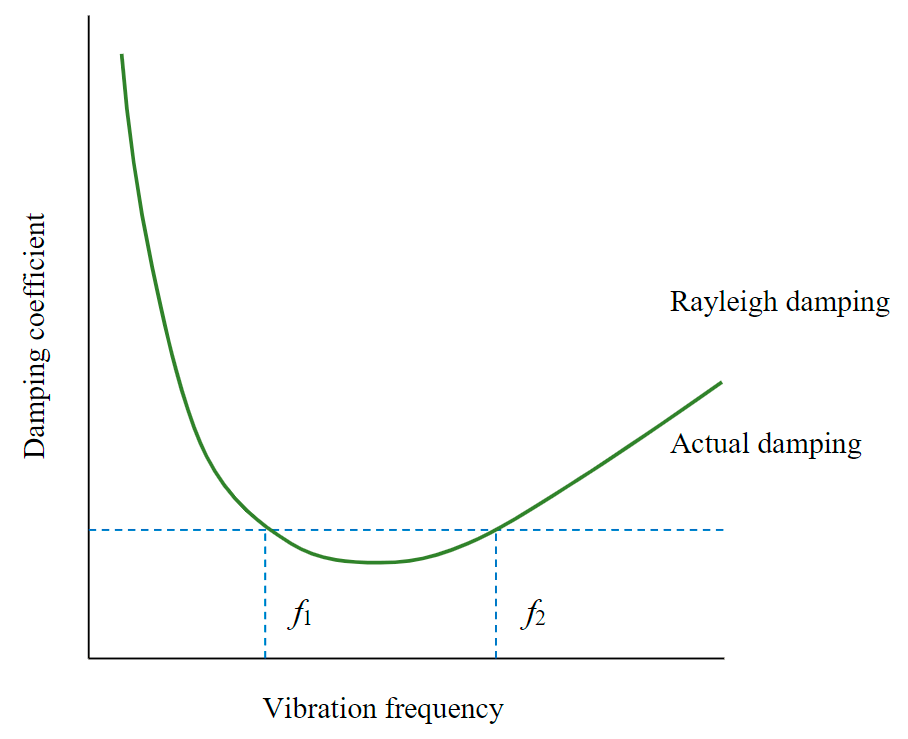
Fig.1. Rayleigh damping ƒ1, ƒ2 - range of variation of vibration frequency [27]
The numerical modeling of seismic wave propagation uses the Rayleigh damping model (Fig.1), which is determined by two coefficients αR and βR, characterizing damping by mass and stiffness, respectively:
where М, K – the mass and stiffness matrices, respectively.
Rayleigh coefficients depend on the oscillation frequency of the system and are determined from the solution of a system of equations:
where ω, ƒ – circular and linear frequencies, respectively, Hz; $\zeta$ – damping coefficient.
By setting the range of linear frequency variation fromƒ1 (smallest) to ƒ2 (largest) and solving equation (8), we obtain formulas for determining Rayleigh coefficients:
For practical calculations, taking the value of the lowest frequency ƒ1 equal to 0 Hz, we get the value of the coefficient αR equal to 0, and the value of the coefficient βR according to the formula:
For the correct solution of the equations for predicting the seismic waves propagation, the condition must be met: the length of the seismic wave is not less than 10-15 characteristic sizes of finite elements [23]. More accurately, this value can be calculated using the formula for longitudinal and transverse waves:
where cp, cs – propagation velocities of longitudinal and transverse seismic waves, m/s; hs, hp – the characteristic size of the final element according to the criterion of propagation of longitudinal and transverse waves, m; E – modulus of deformation, kPa; v – coefficient of transverse deformation; ρ – density, kg/m3.
The seismicity coefficient was determined on the basis of comparing the results of numerical modeling with the results obtained by the empirical formula for determining the velocity of rock particles movement as they move away from the site of initiation of explosives, taking into account energy absorption. In general, the velocity of rock particles movement can be represented as
where R – distance from the blast source, m; Q – the mass of instantaneous blasted explosives, kg; a1, β – constants of the equation that depend on specific mining, geological and technological conditions.
To change the magnitude of the pulse with a mass of an instantaneous blasted explosives equal to 2 kg, equation (12) must be transformed. The obtained dependence relates the velocity to the intensity of the impact, while the indicator b varies from 1.25 to 1.75:
Based on the numerical modeling performed in the planedeformation formulation, it is established that the value of the velocities of rock particles movement in the entire range of the considered values of R deviates significantly from the empirical dependence. The introduction of damping into the system under consideration improves the convergence of the results, but the result still remains imperfect. Consideration of the seismic waves propagation in the spatial formulation allows to obtain good convergence with the data of empirical dependence. Thus, it can be concluded that although the damping coefficient brings the calculation results closer to the actual ones, in order to achieve complete convergence, it is necessary to consider the problem of seismic waves propagation in an elastic medium in the spatial formulation (Fig.2). The application of the planedeformation formulation to solve the problem leads to a conservative solution.
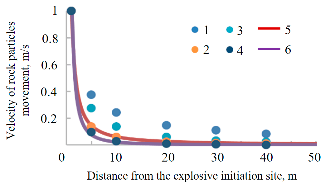
Fig.2.The dependence of the velocity of rock particles movement at distance from the explosive initiation site at various parameters of the numerical model: NM-2D, DR = 0, DR = 5 – the results of the numerical modeling in planedeformation formulation when the damping coefficient is 0 and 5 %; NM-3D, DR = 0, DR = 5 – the results of numerical modeling in a spatial formulation with a damping coefficient 0 and 5 %; empirical upper bound, lower bound – the range of possible values of the velocities of rock particles movement according to empirical dependence 1 – NM-2D, DR = 0; 2 – NM-3D, DR = 0; 3 – NM-2D, DR = 5; 4 – NM-3D, DR = 5; 5 – empirical upper bound; 6 – empirical lower bound
The model of plastic deformation of concrete with accumulation of damages (Concreate Damage Plasticity – CDP) is widely used in predicting the stress-strain state SSS concrete and reinforced concrete structures and, in particular, concrete and shotcreting supports of mine workings [16, 21]. The CDP model makes it possible to comprehensively consider the process of concrete deformation under uniaxial and insignificant edging compressions [14] and take into account alternating loading, as well as the influence of the deformation velocity of the material on its mechanical behavior. Among the disadvantages, one can note the inability of the model to correctly describe the mechanical behavior of concrete under conditions of volumetric compression.
The surface of the plastic flow of the CDP model is given as a dependence:
where $\overline{q}$ – the intensity of normal stresses, kPa; σmax – the maximum main effective stresses, kPa; σc0, σb0 – the elastic limit of concrete under conditions of biaxial compression and uniaxial stress, respectively, kPa; $\overlineσ_c(ε_с^{-pl}),\overlineσ_t(ε_t^{-pl})$ – effective compressive strength of concrete as a function of plastic compressive and tensile deformations, kPa; $\overline{p}$ – average stresses, kPa; Kc – an indicator that determines the shape of the plastic flow surface in the deviatory plane.
In [3, 6], the equations of the relationship between stresses and deformations under uniaxial compression for unreinforced concrete are presented. However, this expression does not allow to correctly describe the deformation of dispersed reinforced concrete in the extreme stage of deformation. To overcome this disadvantage, a modified equation was proposed in [20], which uses one parameter to correct the deformation of dispersed reinforced concrete:
where ƒcm – average strength of concrete under uniaxial compression, kPa; εc – relative concrete deformations; εc.p – relative deformations of dispersed reinforced concrete corresponding to the ultimate strength; Ec1, Eci – secant and tangent deformation modules, kPa.
where Wƒ – fiber consumption by weight, %; εc10 – deformations at the ultimate strength of unreinforced concrete, 2.2·10–3.
The energy of shotcreting destruction under compression Gc varies from 30 to 70 kN/m, unreinforced sprayed concrete under stress Gt – from 0.05 to 0.15 kN/m. When considering reinforced shotcreting, Gt.ƒr indicator was determined by the formula [13]:
where Gt – the value of the energy of unreinforced shotcreting destruction, kN/m; Wƒ – fiber consumption, kg/m3.
The diagram of concrete softening under stress can be idealized in the following form: quantitatively, the diagram is determined by the strength of concrete under uniaxial stress ƒctm, the limit value of deformations at the moment of full crack opening εcr and three indicators – α, p1, p2. The parameter p2 is determined by the formula [13]:
During explosive detonation and the seismic waves formation in the zone closest to the explosive initiation site, energy release was described using the JWL equation of state (John-Lee-Wilkenson model) [25, 33]. The equation of state in units of internal energy stored in a unit of mass Em can be written as
where A, B, R1, R2, ω – model constants selected for each type of explosive; ρ, ρ0 – the density of explosion products and explosives, respectively.
Construction of a numerical model of the SSS forecast of shotcreting support
A reliable forecast of the seismic waves development in the rock mass requires a high discretization density of the computational area, which imposes some restrictions on the numerical model dimension (the element size should be no more than 1/10 of the wavelength) [26]. In this regard, the task was divided into two calculation stages. At the first stage, the prediction of the seismic waves propagation in the immediate vicinity of the explosive initiation site is carried out. On the second – forecasts of the seismic waves propagation to the mine workings and SSS supports [10].
Equivalent indicators of the mechanical characteristics of the rock mass are summarized in Table 1.
Table 1
Calculated physical and mechanical characteristics of the rock mass*
|
Name |
Density, kg/m3 |
Modulus of deformation, MPa |
Coefficient of lateral deformation |
Coupling, MPa |
The angle of internal friction, deg. |
Tensile strength, MPa |
|
Rock |
2900 |
26500 |
0.35 |
6.6 |
43 |
0.5 |
|
Ore |
3000 |
22500 |
0.35 |
6.0 |
41 |
0.5 |
* Report of the Research Institute of VNIITSVETMET “Study of the parameters of the rock mass and determination of ways to control rock pressure”, 2002.
When performing numerical calculations of the forecast of damage to the shotcreting support [28-30], numerical indicators (Table 2) CDP models for unreinforced and reinforced shotcreting with a dosage of 25 and 50 kg/m3 metal fiber were taken. All parameters were obtained for concrete of class B40 (compressive strength). Diagrams of hardening and softening of concrete under loading under conditions of uniaxial compression and tension are shown in Fig.3.
Table 2
Parameters of the CDP model for unreinforced and reinforced with shotcreting*
|
Material |
ρ,kg/m3 |
Rc, MPa |
Rt, MPa |
Gc, kN/m |
Gt, kN/m |
ψ, deg. |
Rbc/Rc |
K |
|
Unreinforced shotcreting, class B40 |
2200 |
25.0 |
1.5 |
30 |
0.15 |
30 |
1.16 |
0.66 |
|
Reinforced shotcreting (RS), class B40, metal fiber consumption – 25 kg/m3 |
2200 |
25.0 |
1.5 |
40 |
2.5 |
30 |
||
|
Reinforced shotcreting, class B40, metal fiber consumption – 50 kg/m3 |
2200 |
25.0 |
1.5 |
50 |
9.2 |
30 |
* SP 63.13330.2018 “Concrete and reinforced concrete structures”.
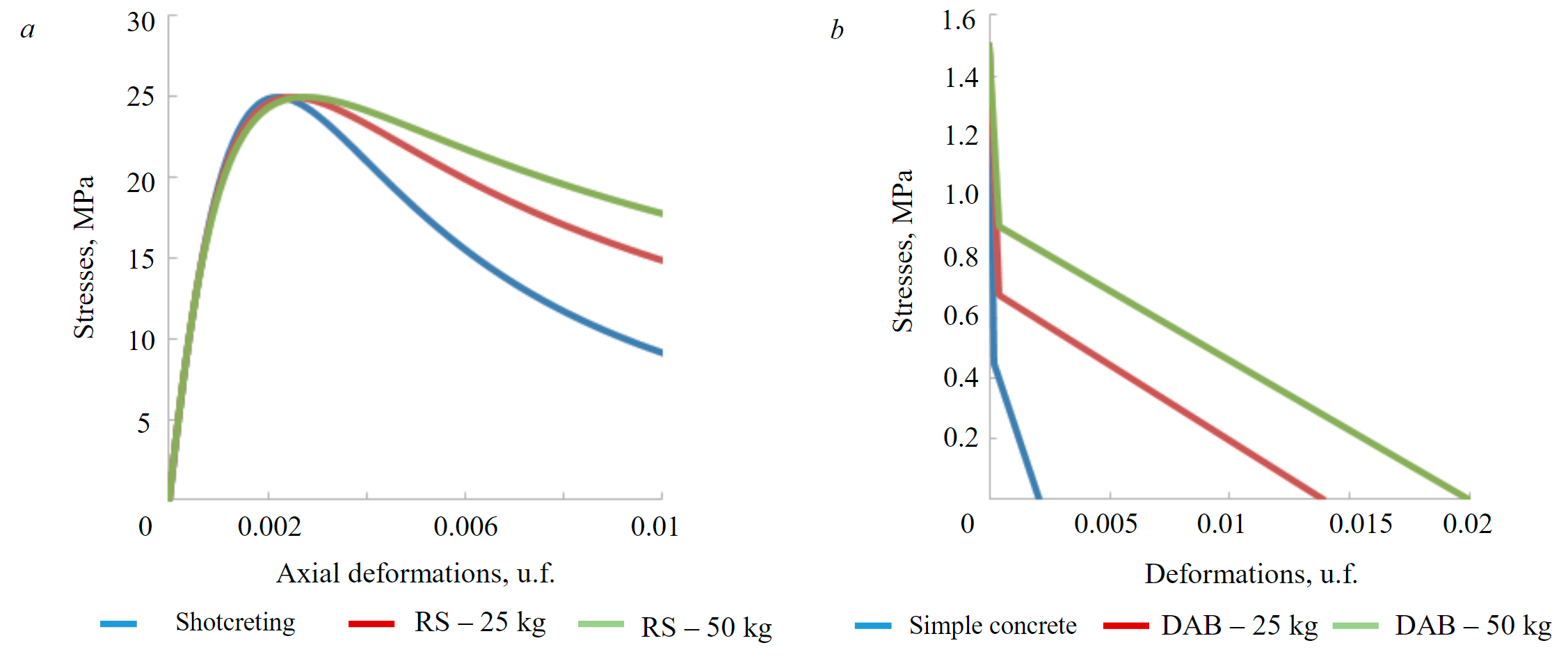
Fig.3. Diagrams of concrete deformation under conditions of uniaxial compression (а) and tension (b)
Numerical modeling of seismic wave propagation at the first stage is performed in a planedeformation formulation. For a typical emulsion explosive, the following constants of the JWL model are accepted: ρ0 = 1140, kg/m3; A = 3.85e11, Pa; B = 5.045e9, Pa; R1 = 5.487; R2 = 1.171; ω = 0.24; cd = 5573, m/s; E0 = 3.26e6, J/m3; pb = 2.1e+010, Pa; Kpd = 3.3e9, Pa.
When developing the model of the first stage, the actual arrangement of explosives in the cut of the mine face was taken into account. The diameter of the borehole is assumed to be 46 mm, the length of the borehole is 3 m. The developed DBO passport includes 43 boreholes. The initiation of explosives is carried out in several stages of deceleration, while the deceleration step is chosen so that seismic waves between different stages of deceleration do not overlap each other. In numerical modeling, the option of blasting only contour boreholes was considered, since with the accepted scheme of initiation of explosives in the current DBO passport, they have the largest mass of explosives at one stage of deceleration and have the greatest impact on the shotcreting support.
Based on the results of the first stage, the velocities of rock particles were determined at the model boundary, which were subsequently transferred as boundary conditions for the seismic waves propagation for the model of the second stage. Based on the built model of the second stage, numerical modeling of the seismic waves propagation in the rock mass was performed and the SSS of the shotcreting support was determined. The SSS forecast of the “support – rock mass” system is made in a planedeformation formulation. Finite elements of the CPE6M type are accepted. The distance between the explosives initiation site and the mine working center is 37.5 m; the mine is arched in shape with dimensions of 4.8 × 4.65 m. As the support of the mine working, the shotcreting is used, and its models are the elastic-plastic CDP model, the characteristics of which are summarized in Table 2. The distance from the center of the model to the boundary of the infinite elements is 100 m. The load from the seismic impact was applied to the internal boundaries of the model (Fig.4) in the form of the resulting movement velocities of rock particles. The seismic load was applied repeatedly (10 cycles) every 0.05 s. When performing calculations, it was shown that this period of load repeatability makes it possible to exclude a significant overlap of seismic waves from seismic loading cycles in the near-contour area of the mine working, which is important for obtaining a “pure” numerical experiment in which the seismic wave from each specific event has a separate effect on the SSS of the rock mass. To exclude the reflection of waves from the boundaries of the model, “infinite elements” are installed along its perimeter.
The size of the finite element grid, according to condition (11), for the Maleyevsky mine at the expected frequency of vibrations of the rock mass caused by the blast, 1000-1500 Hz should not exceed 1.0 m. However, taking into account the actual thickness of the shotcreting support equal to 0.15 and the need to use at least three elements in the thickness of the shotcreting support, the size of the finite elements in the section of the support is assumed to be 0.05 m; the rock mass is divided into elements with characteristic dimensions of 0.05-0.25 m.
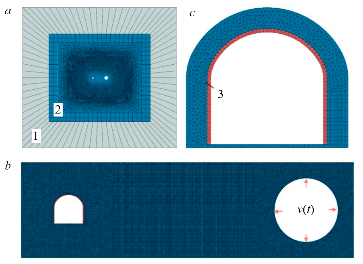
Fig.4. Finite element model for predicting the stress state of the shotcreting support: general view of the model (a), fragments of models of the seismic wave propagation area (b), interaction of shotcreting with the rock mass (c) 1 – zone of infinite elements; 2 – rock mass; 3 – shotcreting support
The seismic impact was set in the form of the resulting velocity on a contour with a radius of 5 m, the value of which was determined based on the model of the first stage. The resulting velocity is conveniently approximated by the dependence:
To set multiple seismic loading, the pulse was calculated according to the formula (20), while the deceleration value between pulse actions was assumed to be equal to 0.05 s. At this deceleration, the superposition of seismic waves did not lead to a significant increase in stresses in the shotcreting support.
Numerical modeling resultsм
Based on the performed calculations, a pattern of seismic wave propagation during the blasting of contour boreholes has been established. The results are shown in the form of plots of rock particle vibrations at a characteristic time (Fig.5). Based on the presented plots, at the initial stage, several sources of seismic wave propagation are formed, which, as they move away from the mine working contour, are combined into a single wave with a certain frequency of rock vibrations and the velocity of rock mass particles movement. It is established that at a distance of 5 m from the contour of the mine working, the formation of a single seismic wave is completed.
The minimum size of the zone of destroyed rocks by a blast, beyond which only elastic waves conditionally propagate, can be determined by the following formula, assuming that the velocity of rock particles movement at which the rock is still destroyed is equal to 1 m/s:
where Q – the mass of instantaneous blasted explosives, kg.
The values of Rppv for the characteristic mass of instantaneous blasted explosives from 1 to 25 kg in one blast source allow to establish that the size of the rock destruction zone from the explosive effect varies from 0.9 to 4.2 m, respectively. Analysis of the presented data shows that the size of the rock destruction zone increases with the increase in the mass of instantaneous blasted explosives. Therefore, the boundary of the zone of application of the velocities of rock particles movement should be moved outside these zones. With DBO for mining, the distance from the mining contour to the zone of formation of a single seismic wave front is outside the zone of rock destruction by blast and can be assumed to be equal to 5 m.
The velocity of movement and rock particles movement at the considered distance from the contour of the mine working are shown in Fig.5. The maximum velocity of rock particles reaches 0.6 m/s, and the maximum movements of rocks is 0.6 mm. The obtained plot of the development of the rock mass movements was used to set boundary conditions in the model of the second stage.
The proposed approach makes it possible to forecast the seismic waves propagation with arbitrary parameters of the mine working section and the DBO passport, as well as significantly reduce the geometric dimension of the model and increase the degree of discretization of the computational area by finite elements.
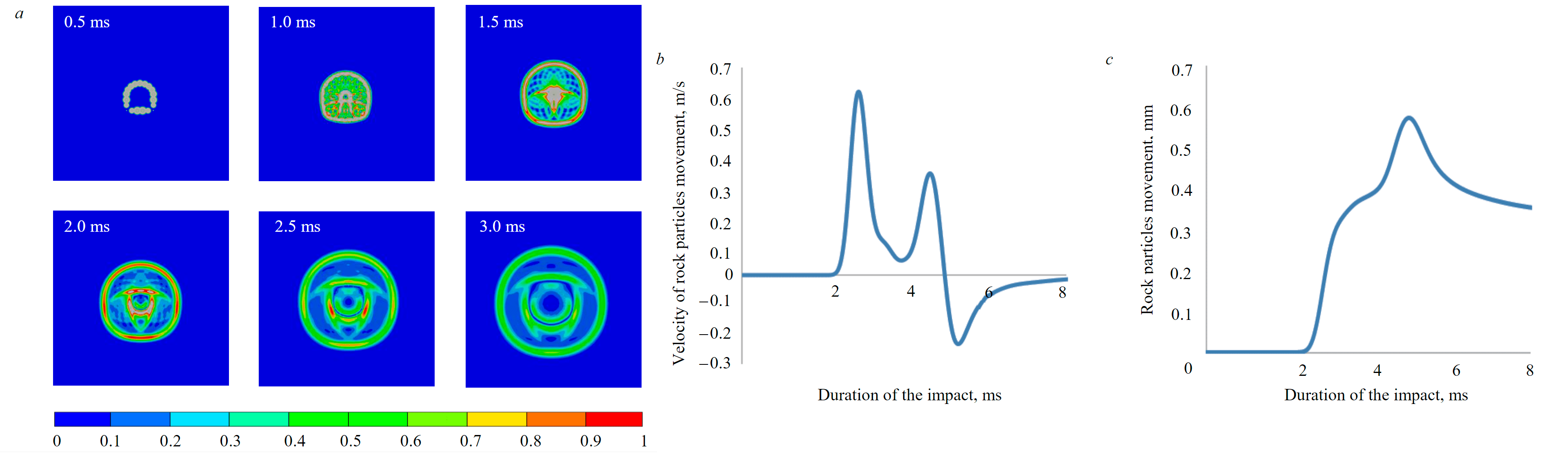
Fig.5. Development of peak velocities of rock particles movement as they move away from the source of the blast: a picture of the velocities of rock particles movement (a), a diagram of the development of the velocity of rock particles movement at a characteristic point (b), movement of rock particles at a characteristic point (c)
The model of the second stage considers the seismic waves propagation to the contour of the mine working [17]. Based on the comparison of the empirical dependence, it was previously established that the rock mass is characterized by a damping coefficient equal to 5 %. To determine the actual parameters of the Rayleigh equation, the results of numerical modeling are compared with the results of instrumental measurements of changes in the displacement velocities of rock particles on the contour of the mine working. Assuming that the damping coefficient varies from 2 to 5 %, and having calculated the forecast of seismic waves for the site of instrumental measurements, we obtain a change in the velocities of rock particles movement from 0.07 to 0.25 m/s. The peak movement velocity of rock particles according to instrumental measurements is 0.067 m/s, which corresponds to the predicted value with a damping coefficient of 5 %. Thus, the pre-selected value of the damping coefficient is confirmed based on comparison with instrumental measurements. The results of the calculation of the stress state of the shotcreting support are presented in the form of dependences of changes in the main minimum stresses during each cycle of seismic action (Fig.6).
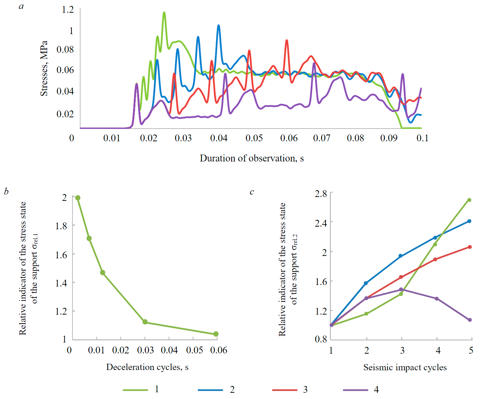
Fig.6. Formation of the stress state of the shotcreting support with repeated seismic impact: the development of stress in the shotcreting support over time (a), patterns of changes in the magnitude of stresses in the support at the final stage of seismic impact (b), patterns of changes in the magnitude of stresses in the support from deceleration between cycles of seismic impact (c) 1 – 0.001 s; 2 – 0.005 s; 3 – 0.01 s; 4 – 0.025 s
When performing calculations, it is assumed that vmax in the area of application of the boundary condition v(t) is equal to 1 m/s. Stages equal to 0.001, 0.005, 0.01 and 0.025 s were taken to assess the effect of deceleration between cycles of seismic impact. Based on the presented data, the stresses in the shotcreting support significantly increase during seismic action. With repeated loading, the stresses continue to increase and the higher they are, the shorter the duration of the deceleration stage between blasts. To analyze the obtained data, we introduce two indicators – σrel.1 and σrel.2.
The first indicator σrel.1 characterizes how many times the stresses increase after five cycles of seismic impact from blasting, attributed to the magnitude of the stress in the shotcreting support at the deceleration stage of 0.05 s, which can be conditionally taken as the boundary value of deceleration, at which the imposition of seismic waves does not lead to an additional increase in stresses in the shotcreting support.
The second indicator σrel.2 characterizes how many times the stresses in the shotcreting support increase at a specific stage of deceleration relative to the value of the stress at this stage of deceleration obtained during the first cycle of seismic load application.
Presenting the obtained data in graphical form (Fig.6, a), we note that the stress state of the shotcreting support with repeated application of seismic load largely depends on the duration of the deceleration stage. Thus, with a deceleration between blasts equal to 0.001 s, the stresses increase twice, at 0.005 s – by 1.7 times, and at 0.01 s – by 1.45 times. The growth of stresses under repeated loading between cycles of seismic action is nonlinear (Fig.6, a), while the nature of the change in the value of the coefficient σrel.2 depends on the duration of the deceleration stage. At deceleration values from 0.001 to 0.01 s, an increase in the stress state is observed from cycle to cycle of seismic action, while at a deceleration value of 0.025 s, an increase in stresses is observed in the first cycles of seismic action, and then a fall occurs, which is expressed in a decrease in the coefficient σrel.2. Thus, it is necessary to consider the entire range of seismic loading of the support, and not be limited to the final stage, since the magnitude of the maximum stresses in the support is not always confined to the final stage.
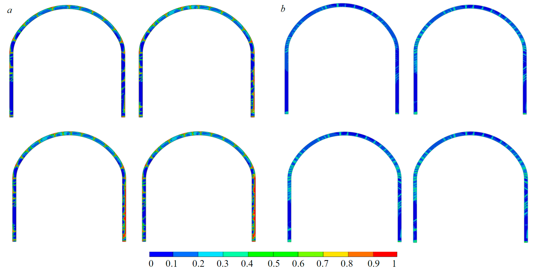
Fig.7. Indicators of damage to the shotcreting support: unreinforced (a) and dispersed reinforced shotcreting (b)
The development of stresses in the shotcreting support in the elastic stage allows to form an idea of the influence of multiple seismic impacts on the support. Due to such a scheme of idealization of the support, it is impossible to assess the accumulation of damage and take into account the redistribution of stresses in the support as a result of changes in its mechanical state [3, 7]. The forecast of damage to the shotcreting support, when considered as an elastic-plastic medium with the accumulation of damage, is presented in the form of plots, the indicator of which varies from 0 to 1 (Fig.7). After the first cycle of seismic impact, the damage zones actively spread along the perimeter of the support, forming a set of radial cracks. Subsequent stages of seismic impact continue to negatively affect the degree of damage to the unreinforced shotcreting support, but the main growth of damage zones is confined to the area from the side of the seismic wave propagation. Another type of damage to the dispersed reinforced shotcreting support [24] can be observed from the obtained results. Repeated seismic impact also uniformly along the perimeter of the support increases the degree of its damage, which differs significantly in unreinforced and dispersed reinforced support [19]. Thus, unreinforced shotcreting after the first cycle of seismic impact receives the germination of cracks, and subsequent cycles significantly enhance this effect, forming zones with a damage index close to one. When considering the support made of dispersed reinforced shotcreting, it can be seen that the degree of damage rarely goes beyond 0.3-0.4, and repeated loading does not have a serious effect on the change in this indicator, only the area of damage to the support increases.
The location of the seismic impact source relative to the mine workings significantly changes the nature of the damage. When the source of the seismic impact is located above the arch of the mine workings, the formation of separate local zones of damage to the shotcreting support is observed, and not their spread around the entire perimeter. This is due to the peculiarities of the nature of the deformation of the support during the passing of seismic waves.
Conclusion
The effects of blasting operations on the shotcreting support of mine workings are considered. The results of field observations of the workings of Maleyevsky and other mines have shown that the mine workings located in the zone of influence of mass blasts and secured with unreinforced shotcreting may have serious problems with ensuring their stability.
On the basis of the performed studies, a method for assessing the multiple explosive effects on the SSS of the shotcreting support of the mine workings is proposed. The methodology includes two stages of calculations and is based on the implementation of the SSS support forecast, taking into account the accumulation of damage. It has been established that repeated seismic impact significantly affects the stress state of the support and the degree of its damage, while the smaller the deceleration cycle, the more intense this impact is. The rate of damage accumulation in dispersed reinforced shotcreting support is less than in unreinforced shotcreting. Even after five impacts, the bearing capacity of the dispersed reinforced shotcreting support remains at a sufficient level to ensure the stability of the mine workings, while the shotcreting support may lose its bearing capacity after 1-2 cycles of seismic loading. It is determined that when calculating the dispersed reinforced shotcreting support of a mine working for dynamic impact, located in the zone of influence of blasting operations, in the first approximation, the strength of the shotcreting is permissible to take 30 % less than its peak value.
It has been established that the position of the blast source relative to the mine working and its shape also have a significant impact on both the intensity of damage to the shotcreting support and the qualitative distribution of these zones along the perimeter of the support.
References
- Vinogradov Yu.I., Khokhlov S.V., Sokolov S.T. Features of seismic monitoring during blasting operations near an existing gas pipeline. Izvestiya Tulskogo gosudarstvennogo universiteta. 2019. N 1, p. 296-305 (in Russian).
- Menzhulin M.G., Afanasev P.I., Korshunov G.I., Shchipachev A.S. The impact of blasting operations of the Zarechnyi mine on the permanent mine workings of the Taldinskaya-Zapadnaya-2 mine. Mining informational and analytical bulletin. 2015. N S7, p. 591-596 (in Russian).
- Goldobina L.O., Sinegubov V.Yu. Investigation of the properties of fiber concrete under various conditions of strength gain. COLLOQUIUM-JOURNAL. 2019. N 13-3 (37), p. 24-30 (in Russian).
- Gospodarikov A.P., Vykhodtsev Ya.N., Zatsepin M.A. Mathematical modeling of seismic explosion waves impact on rock mass with a working. Journal of Mining Institute. 2017. Vol. 226, p. 405-411. DOI: 10.25515/PMI.2017.4.405
- Gospodarikov A.P., Zatsepin M.A. Mathematical modeling of nonlinear boundary value problems of geomechanics. Gornyi zhurnal. 2019. N 12, p. 16-20. DOI: 10.17580/gzh.2019.12.03 (in Russian).
- Trushko V.L., Protosenya A.G., Ogorodnikov Yu.N., Kolosova O.V. Patterns of mine workings deformation under dynamic forms of rock pressure manifestations. Journal of Mining Institute. 2001. Vol. 149, p. 185-187 (in Russian).
- Morozov V.I., Pukharenko Yu.V. The effectiveness of the use of fiber concrete in structures under dynamic influences. Vestnik MSGU. 2014. Vol. 9. N 3, p. 189-196. DOI: 10.22227/1997-0935.2014.3.189-196 (in Russian).
- Zubkov A.A., Latkin V.V., Neugomonov S.S., Volkov P.V. Promising ways of fixing mine workings in underground mines. Mining informational and analytical bulletin. 2014. N S1-1, p. 106-117 (in Russian).
- Kholodilov A.N., Gendler S.G., Vinogradova E.Yu., Shilyaev A.S. Problems of ensuring seismic safety in the construction of transport tunnels. Journal of Mining Institute. 2007. Vol. 171, p. 229-232 (in Russian).
- Ekvist B.V Improving the safety of short-delayed blasting. Mining informational and analytical bulletin. 2017. N 5, p. 389-394 (in Russian).
- Ekvist B.V., Gorbonos M.G. Improving the safety of seismic manifestations of short-delayed blasting at mining enterprises. Gornyi zhurnal. 2016. N 10, p. 34-36. DOI: 10.17580/gzh.2016.10.06
- Erten O., Konak G., Kizil M.S. et al. Analysis of quarry-blast-induced ground vibrations to mitigate their adverse effects on nearby structures. International Journal of Mining and Mineral Engineering. 2009. Vol. 1. Iss. 4, p. 313-326. DOI: 10.1504/IJMME.2009.029317
- Ziaran S., Musil S., Cekan M., Chlebo O. Analysis of seismic waves generated by blasting operations and their response on buildings. International Journal of Environmental, Chemical, Ecological, Geological and Geophysical Engineering. 2013. Vol. 7. N 11, p. 769-774.
- Mingsheng Zhao, Dong Huang, Maosen Cao et al. An Energy-Based Safety Evaluation Index of Blast Vibration. Shock and Vibration. 2015. Vol. 2015. N 698193. DOI: 10.1155/2015/698193
- Bernardo G., Guida A., Mecca I. Advancements in shotcrete technology. 14th International Conference on Studies, Repairs and Maintenance of Heritage Architecture (STREMAH 2015), 13-15 July 2015, A Coruna, Spain. WIT Press, 2015. Vol. 153, p. 591-602. DOI: 10.2495/STR150491
- Borman P., Engdahl E.R., Kind R. Seismic wave propagation and Earth models. German Research Center for Geosciences. 2012, p. 105. DOI: 10.2312/GFZ.NMSOP-2_ch2
- Grassl P., Xenos D., Nyström U. et al. CDPM2: a damage-plasticity approach to modelling the failure of concrete. International Journal of Solids and Structures. 2013. Vol. 50. Iss. 24, p. 3805-3816. DOI:10.1016/j.ijsolstr.2013.07.008
- Karasev M.A., Sotnikov R.O., Sinegubov V.U. et al. Development of a model for predicting the dynamic effect on the stability of rock excavation. International Conference “Complex equipment of quality control laboratories”, 14-17 May 2019, Saint Petersburg, Russian Federation. Journal of Physics: Conference Series, 2019. Vol. 1384, p. 1230-1236. DOI: 10.1088/1742-6596/1384/1/012051
- Eduardo A.R., Manzoli O.L., Bitencourt Jr.A.G. et al. Failure behavior modeling of slender reinforced concrete columns subjected to eccentric load. Latin American Journal of Solids and Structures. 2015. Vol. 12 (3), p. 520-541. DOI: 10.1590/1679-78251224
- Heravi A.A., Smirnova O.M., Mechtcherine V.S. Effect of strain rate and fiber type on tensile behavior of high-strength strain-hardening cement-based composites (HS-SHCC). International Conference on Strain-Hardening Cement-Based Composites (SHCC 2017): Strain-Hardening Cement-Based Composites, 18-20 September 2018, Dresden, Germany. Springer, 2018. Vol. 15, p. 266-274. DOI: 10.1007/978-94-024-1194-2_31
- Hoek E., Carter T.G., Diederichs M.S. Quantification of the Geological Strength Index Chart. 47th US Rock Mechanics. Geomechanics Symposium, 23-26 June 2013, San Francisco, USA. OnePetro, 2013, p. 9.
- Meda A., Rinaldi Z., Spagnuolo S., Rivaz B. Hybrid precast tunnel segments in fiber reinforced concrete with glass fiber reinforced bars. Tunnelling and Underground Space Technology. 2019. Vol. 86, p. 100-112. DOI:10.1016/j.tust.2019.01.016
- Johnson G.R., Holmquist T.J. An improved computational constitutive model for brittle materials. AIP Conference Proceedings. 2008. Vol. 309. Iss. 1. DOI: 10.1063/1.46199
- Khaled M., Abdel Rahman K., Abo Makarem A. Experimental techniques to reduce blasting vibration level, Tourah, Cairo, Egypt. Proceedings of the 33rd Annual Conference of Explosive and Blasting Technique, 28-31 January 2007, Nashville, USA. ISEE, 2007. Vol. 1, p. 136-152. URL: http://www.ascom.com.eg/files/ISEE.pdf (date access 14.06.2021)
- Krätzig W.B., Pölling R. An elasto-plastic damage model for reinforced concrete with minimum number of material parameters. Computers & Structures. 2004. Vol. 82. Iss. 15-16, p. 1201-1215. DOI: 10.1016/j.compstruc.2004.03.002
- Liu H. Dynamic analysis of subway structures under blast loading. Geotechnical and Geological Engineer. 2009. Vol. 27, p. 699-711. DOI: 10.1007/s10706-009-9269-9
- Esfahani M.H., Hejazi F., Vaghei R. et al. Simplified Damage Plasticity Model for Concrete. Structural Engineering International. 2017. Vol. 27. Iss. 1, p. 68-78. DOI: 10.2749/101686616X1081
- Smirnova O.M., Kharitonov A.M., Belentsov Y.A. Influence of polyolefin fibers on the strength and deformability properties of road pavement concrete. Journal of Traffic and Transportation Engineering (English Edition). 2019. Vol. 6. N 4, p. 407-417. DOI: 10.1016/j.jtte.2017.12.004
- Smirnova O.M., Shubin A.A., Potseshkovskaya I.V. Strength and Deformability Properties of Polyolefin Macrofibers Reinforced Concrete. International Journal of Applied Engineering Research. 2017. Vol. 12. N 20, p. 9397-9404.
- Tulin P.K., Shubin A.A., Potseshkovskaya I.V. Research of the Effect of the Concrete Reinforcement Structure on the Stress-Strain State of Structures. International Journal of Applied Engineering Research. 2017. Vol. 8. N 12, p. 1742-1751.
- Yan Bo, Xinwu Zeng, Yuan Li. Subsection forward modeling method of blasting stress wave underground. Mathematical problems in engineering. 2015. Vol. 2015. N 678468. DOI: 10.1155/2015/678468
- Yang Tao, Jianfey Chen. Concrete damage plasticity model for modeling FRP-to-concrete bond behavior. Journal of Composites for Construction. 2015. Vol. 19. Iss. 1. DOI: 10.1061/(ASCE)CC.1943-5614.0000482
- Choi S., Wang J., Mufakh G., Dwyre E. 3D nonlinear blast model analysis for underground structures. GeoCongress, 26 February – 1 March 2006, Atlanta, USA. American Society of Civil Engineers, 2006, p. 1-6. DOI: 10.1061/40803(187)206