
Prediction of the stress-strain state and stability of the front of tunnel face at the intersection of disturbed zones of the soil mass
- 1 — Ph.D., Dr.Sci. Professor Saint Petersburg Mining University ▪ Orcid ▪ Elibrary ▪ Scopus
- 2 — Ph.D. Assistant Lecturer Saint Petersburg Mining University ▪ Orcid
- 3 — Ph.D. Associate Professor Saint Petersburg Mining University ▪ Orcid

Abstract
The article presents a numerical solution of the spatial elastic-plastic problem of determining the stability of the tunnel face soils at the intersection of disturbed zones of the soil mass. The relevance of the study is related to the need to take into account the zones of disturbed soils when assessing the face stability to calculate the parameters of the support. Based on the finite element method implemented in the PLAXIS 3D software package, the construction of a finite element system "soil mass-disturbance-face support" and modeling of the intersection of the disturbed zones of the soil mass were performed. To assess the condition of soils, deformation and strength criteria are taken. The deformation criterion is expressed by the value of the calculated displacement of the tunnel contour in the face, and the strength criterion - by the safety coefficient until the maximum values of the stress state are reached according to the Coulomb–Mohr criterion. The results of the study are presented in the form of histograms of the safety coefficient dependences on the distance to the disturbance at different bending stiffness of the face support structure, as well as the isofields of deformation development. The parameters of rockfall formation in the face zone at the intersection of zones of disturbed soils were determined. The local decrease in strength and deformation properties in the rock mass along the tunnel track should be taken into account when assessing the stability of the tunnel face and calculating the parameters of the support. Within the framework of the constructed closed system, a qualitative agreement of the simulation results with the case of a collapse in the face during the construction of the Vladimirskaya-2 station of the St. Petersburg Metro was obtained.
None
Introduction
The underground space of Saint Petersburg has a complex structure and is characterized by the presence of tectonic faults [1], areas of lifting and lowering of geological blocks with low geodynamic mobility [2]. This creates unfavorable conditions for the construction and operation of metro tunnels. Localized disturbing zones have been formed in the rock mass, the need to cross them may complicate the conditions for the construction of tunnels. The term “disturbing” in the article refers to a change in the strength and deformation properties of an engineering-geological element for man-made or other reasons. Studies have revealed localization of a decrease in strength parameters and deformation characteristics of soils in the rock mass up to two times [2-4]. Among the reasons leading to a decrease in strength properties are the processes of biochemical weathering, decompression and softening with increasing humidity, as well as the living activity of natural and foreign microbiota [5, 6]. The cases of the soil collapse of the tunneling face during the construction of the Saint Petersburg metro are given in [7].
The presence of disturbing zones in the rock mass determines new requirements for the design of the construction of tunnels and transfer stations. One of the risk factors in the construction of an underground structure is the possibility of soil collapse in the face [8-10]. The probability of this risk increases significantly when the face approaches the site of a local decrease in the strength of the rock mass. In this regard, when assessing the stability of the face soils, it becomes necessary to take into account the structural features of the soil mass. The relevance of the study is related to the complexity and insufficient investigation of the stress-strain state of a physically nonlinear soil mass in disturbed zones [11, 12].
Most of the work on determining stability is based on justifying the necessary pressure on the soil outcrop from the tunnel side, which is true for mechanized tunneling [13-16]. In the works [17, 18], the stability of the tunnel face of flat-lying formation is analyzed. An approach to assessing the face stability is described from the point of view of two groups of limiting conditions, exceeding the criteria of which leads to the impossibility of operating the tunnel, loss of operational suitability, determined by subsidence on the surface [19]. An analytical review of approaches to the assessment of subsidence on the surface is presented in [20]. The work [21] is devoted to the prediction of the open face stability. In the article [22], a study of the face stability during the tunnel at a depth of 8 m from the bottom of quaternary sediments was carried out. Together with the open face scenario, scenarios with different pressure on the face surface from the tunnel side were investigated [23, 24]. A decrease in displacements was revealed as the resistance from the support side increased. Works [25, 26] are devoted to the analysis of the effect of the face support on the stress-strain state. The method of the face timbering with anchors is described in the patent [27]. In the article [26], a method of modeling anchor support has been developed taking into account the anchoring in the lock. The results of field observations of the face surface deformations are presented. The influence of the bending stiffness of the timbering constructions on the deformation of the rock mass is demonstrated. The work [28] is devoted to the assessment of the stress state in the rock mass. It can be concluded that the methodological approach associated with the determination of stability through distributed pressure on the face does not take into account the formation of the stress-strain state of the face soils depending on the bending stiffness of the face timbering structure. The paper [29] describes the stability of an open vertical outcrop in an undrained rock mass with undrained shear strength. The work [30] is devoted to the face stability in a drained rock mass with adhesion and internal friction. Works [31, 32] and research [33] on the stress-strain state of face soils in zones of heterogeneous soils are devoted to the assessment of the stress-strain state of workings near the disturbance. The method of calculating the parameters of the support in the face by the method of limiting balance was considered in [34]. The criterion of stability of soil outcrops adopted in domestic engineering practice is described in [35].
Problem statement
Rockfall formation during tunneling is associated with the activation of deformation processes in the face zone, which will reach the earth's surface and lead to additional yield of the buildings foundation. Insufficient knowledge of the process of rockfall formation in clays under the influence of a combination of factors and the lack of a method for calculating the load on the face support in disturbed soils cause the need to predict the stress-strain state in the tunnel face.
The purpose of the study is to investigate the regularity of the rockfall formation and to study the state of face stability in the zone of disturbed soils. The presence of a predictive view of the dynamics of changes in the state of stability and loss of face soils balance at the intersection of the zone of disturbed soils will allow to qualitatively change the approach to the design of the temporary face support, reduce the probability of the risk of the unpredictable deformations development on the earth's surface, and to preserve the buildings undermined by an underground structure. The achievement of the purpose is possible with the calculation of the parameters of the support that ensure the stability of the face soils and their balance in the face. The tasks of the study are: assessment of the impact of the stiffness of the support on the stability of soils in the face [36]; comparison of the stiffness of the support with the value of the equivalent resistance from the support; study of the factors causing the loss of stability and balance of the soils of the face; identification of the dynamics of changes in the stress-strain state and the stability criterion as the face approaches the disturbance zone, taking into account the properties of rocks in the disturbed zone [37].
The paper proposes, on the basis of an elastic-plastic model with hardening and a strength criterion based on the ratio of maximum tangential stresses to their limiting values, to predict the stable state and the zone of possible collapse.
Research methods
The problem under consideration in the mathematical formulation belongs to the class of elastic-plastic problems with an unknown boundary, which is determined in the process of its solution. It is known [35, 38] that these problems are difficult to obtain an analytical solution even in a flat formulation. The paper considers the spatial formulation of the problem, the solution of which has not yet been developed by the analytical method. Therefore, a numerical solution method was used. The predictive model is based on the method of spatial finite element modeling of geomechanical processes during the construction of a tunnel in the zone of disturbance of the rock mass with implementation in the software package.
There is an active redistribution of stresses and deformations in the face zone. To assess the stress level, it is proposed to use the strength criterion, the deformation level – the deformation criterion [39]. As a deformation criterion, the stability criterion adopted in engineering practice is ta-ken, expressed in terms of the calculated displacement of the contour of the underground structure. Depending on the value of the implemented contour displacements and the type of rocks, four categories of rock stability are identified.
The condition [40] is accepted as a strength criterion of stability in the outcrops of the tunnel face soils:
where τ – the value of the greatest tangential stress associated with the Coulomb – Mohr strength criterion, MPa; τsf – the estimated minimum value of the tangential stress required for ba-lance in the design scenario, MPa.
To estimate the SF parameter, numerical modeling was performed in a spatial formulation using a sequential decrease in the strength properties of the soil mass in the PLAXIS 3D software package. The calculation algorithm was reduced to calculations of a set of balanced states of the system with consistently introduced unbalanced forces associated with a decrease in strength. At the end of each calculation stage, the geomechanical system was in a balanced state, however, at the phase of numerical calculation of SF, the algorithm provides for a decrease in the strength properties of the rock mass. To do this, unbalanced forces were introduced into the model, and the balance of the system was disturbed. The imbalance of forces led to the development of deformations. At the same time, the incremental ratio of deformations caused by the introduction of new unbalanced forces at two adjacent calculation steps was subjected to constant analysis. This algorithm was repeated until an avalanche-like growth of deformations was recorded at the control point (Fig.1) between successive steps of introducing unbalanced forces. At this stage of the calculation, a constant value of SF is achieved, numerically reflecting the criterion of soil strength as the ratio of tangential stresses in the rock mass to the limiting stresses at which a shift along the slip site is realized.
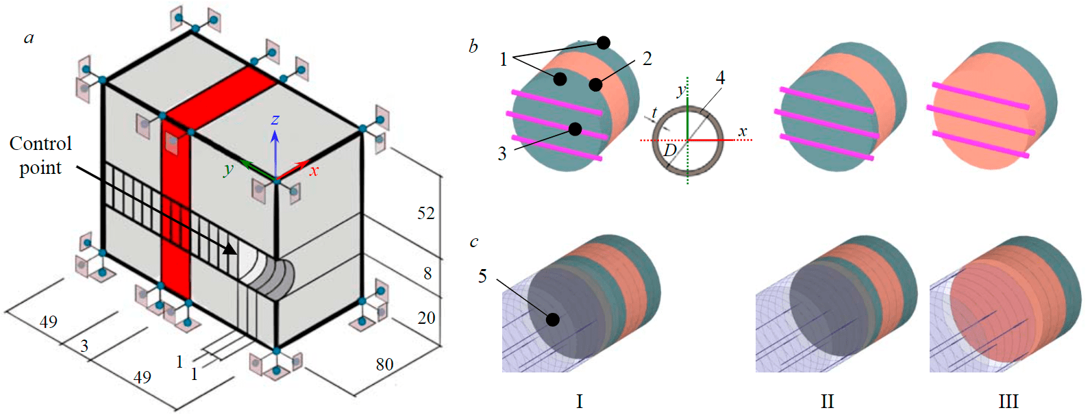
Fig.1. The calculation scheme (a) and the stages of the tunnel: modeling the work of the support in an explicit form (b); in an equivalent form (c) at a distance of 2 m from the violation (I), 1 m (II), on the violation (III) 1 – unbroken rock mass; 2 – structural and mechanical disturbance; 3 – beam element of finite bending stiffness (bunton); 4 – cross section of bunton; 5 – uniformly distributed equivalent pressure
The system “soil mass – disturbance – face support” was modeled as follows. Two calculated geological elements were used as a continuous medium, one of which was described by the properties of an unbroken rock mass, the other – by the properties of a disturbed one. Plate elements with a thickness of 0.35 m were used as lining elements. The temporary face support was modeled using pipes of various diameters. The sealing of pipes into the rock mass was assumed to be equal to 0.35 m. The parameters of the physical and mechanical properties of the soil are presented in the table.
Material Model Parameters
|
Parameter |
Outside the disturbing zone |
In the disturbing zone |
|
Volume weight of non-saturated soil Υunsat, kN/m3 |
22 |
22 |
|
Volumetric weight of water-saturated soil Υsat, kN/m3 |
22 |
22 |
|
Destruction coefficient Rf |
0.9 |
0.9 |
|
Initial porosity coefficient eint |
0.5 |
0.5 |
|
The nonlinearity parameter m |
0.75 |
0.75 |
|
Poisson's ratio during unloading vur |
0.2 |
0.2 |
|
Strength criterion |
Coulomb – Mohr |
Coulomb – Mohr |
|
Modulus of deformations at 50% strength Eref50, MPa |
75 |
50 |
|
Modulus of deformations during unloading Erefur, MPa |
225 |
150 |
|
Effective adhesion с', kPa |
75 |
25 |
|
Effective angle of internal friction φ', deg. |
12 |
6 |
|
Tensile strength σt, kPa |
400 |
0 |
|
Over-consolidation ratio OCR |
10 |
3 |
The sequence of carrying out a predictive assessment of the face stability in the disturbed zone: assignment of boundary conditions of the spatial model; justification of the size of the disturbed zone and the accepted physical and mechanical parameters of the accepted model; allocation in the rock mass the area of influence of the disturbed zone on the controlled parameters of the stress-strain state of the medium; determination of the dynamics of changes in the SF coefficient based on modeling the work of the support at each stage of tunnel construction when approaching the disturbance.
The vertical boundaries of the model are fixed from moving in normal directions, but can move freely in the plane of fixation. The lower boundary of the model is fixed from moving in any direction, while the soil surface is free from fixing (Fig.1). The diameter of the tunnel was set to 8 m. The thickness of the zone of unstable rocks is 3 m. The vertical lines in Fig.1 show the stages of tunnel development. The amount of lagging of the lining from the face is 1 m. The width of the lining ring is 1 m. The change in the bending stiffness of the beam elements was achieved by changing the diameter of the buntons. The grade of steel and the thickness of the pipe wall remained constant.
Results
Determination of the effect of the stiffness of the support on the stability of rocks in the face
To determine the category of stability, isofields of movements of the face surface were constructed depending on the stiffness of the temporary support (Fig.2). Despite the fact that the strength criterion on the face surface (SF = 1.16) will be met in case of a violation when timbering the face with buntons with a diameter of 150 mm, according to the deformation criterion of stability at a displacement level of 240 mm, the condition of the rocks is classified as unstable.
With a diameter of 450 mm of the buntons, deformations of about 7 cm are realized in the face, which, in accordance with the deformation criterion proposed by N.S.Bulychev, belongs to the category of medium-stable state of sedimentary rocks. In the study of strength for the scenario of timbering the face with buntons with a diameter of 450 mm, the strength criterion will also be satisfied (SF = 1.33), and according to the deformability factor, the condition of the soils in the face will be medium-stable.
Based on the criterion of stability in deformability and strength, it can be concluded that with a decrease in the bending stiffness of the temporary face timbering, a change in the state of stability occurs, i.e. the rationally selected stiffness of the temporary face support can affect the stability of rocks in the face.
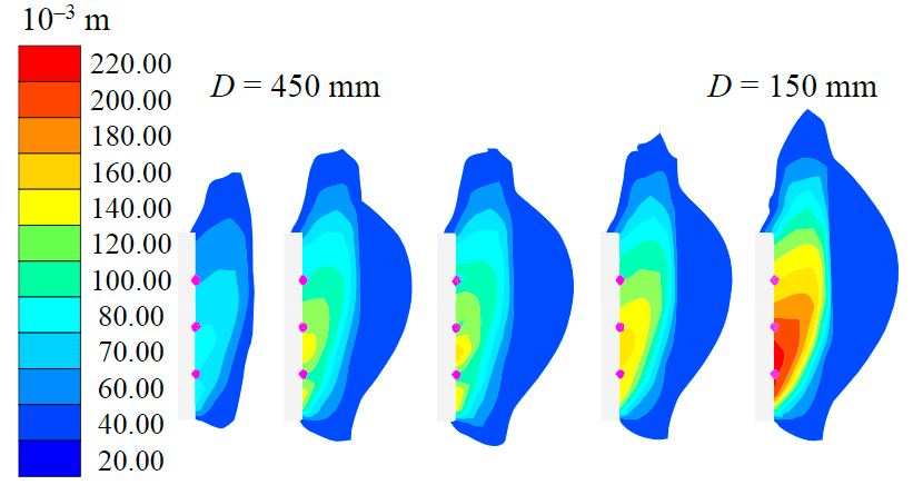
Fig.2. Isofields of displacements during the calculation phase
Determination of the value of the equivalent resistance from the side of the support
The influence of pressure distributed over the face surface on deformation was investigated in [41]. In the work [42], the dependence of the resistance pressure on the change of the strength parameters of the rock mass was revealed. To investigate the possibility of setting the stiffness of the timbering by equivalent pressure from the side of the support, modeling and comparison of collapse zones from the Coulomb – Mohr strength criterion were carried out. Using the SF detection algorithm, the volume of rock involved in the displacement processes was allocated in the rock mass. The formed rockfall can be visualized at the stage of determining the SF criterion with the help of deformation increment isofields. Figure 3 shows the results of determining the shape of the loss of balance of the face rocks with the diameter of temporary structures for the face timbering with beam elements with a diameter of 150 mm (Fig.3, a) and an equivalent pressure of 18.87 kPa (Fig.3, b). The blue color in Fig.3 indicates the surface that is the boundary of the increment of displacements at the SF determination stage, beyond this surface, deformations associated with the introduction of unbalanced forces are not realized in the rock mass and the Coulomb – Mohr strength condition is met.
The compared volumes of soils involved in deformation allow to conclude that the loss of strength occurs according to similar scenarios. Elongated upward rockfall is typical for a disturbed soil mass and is associated with the accumulation and increase of plastic shear deformations and tangential stresses that increase when approaching the disturbance.
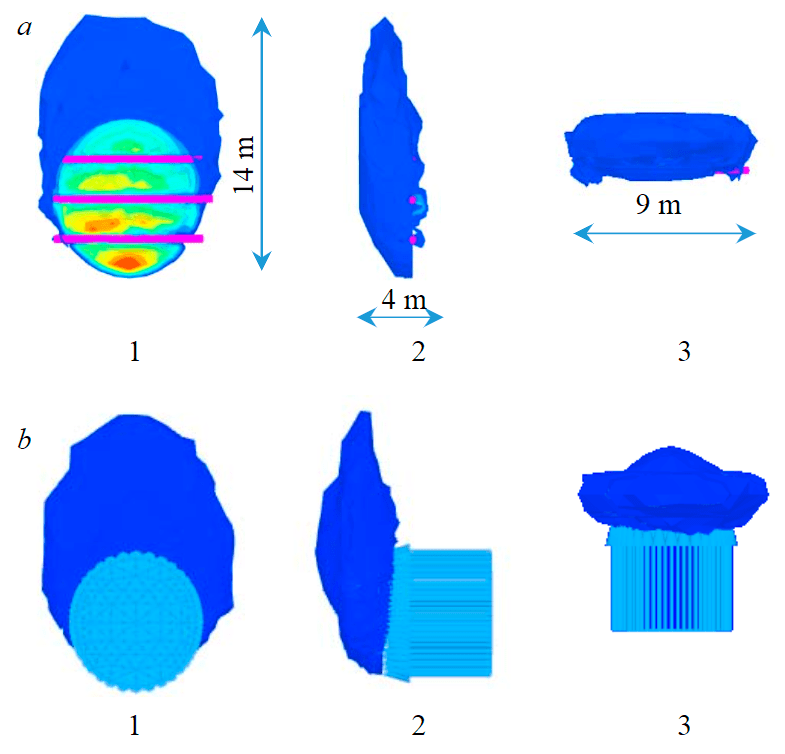
Fig.3. The result of forecasting the zone of possible rockfall under load on the face: a – the main species with the diameter of buntons of 150 mm; b – the main species at an equivalent pressure of 18.87 kPa; 1 – front view; 2 – left view; 3 – top view
Determination of the effect of changes in the stress-strain state on the strength of rocks in the face
When the face approaches the zone of disturbed soils, for all calculated scenarios of the face timbering, an increase in the volume of disturbed soils involved in shear processes occurs. For a qualitative comparison of the results by the strength criterion, the ratios of the stresses acting in the rock mass to the limiting tangential stresses of the open face of the tunnel were determined (Fig.4). According to the stress isofield, the volumes of disturbed soils involved in shear processes were determined.
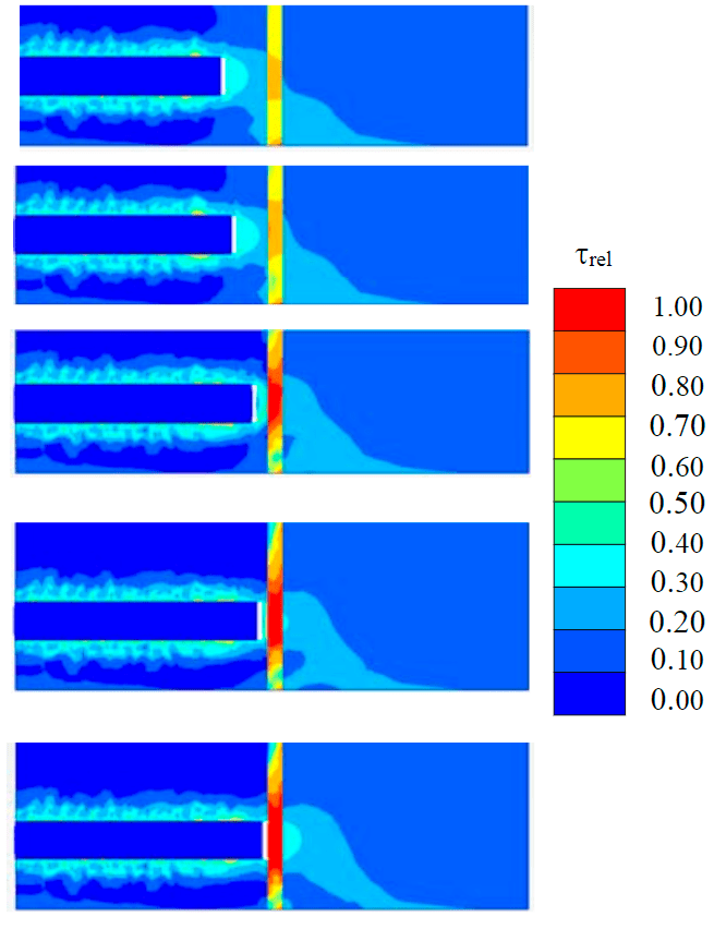
Fig.4. Isofields of the ratio of tangential stresses acting in therock mass to the limiting ones
Dynamics of changes in the SF criterion depending on the distance to the zone of disturbance and the type of support
The study of the dynamics of changes in SF began in the zone of influence of disturbance at a distance of 2 m from the violation. The determination of the zone of influence is justified by preliminary calculations of displacements along the axis of the tunnel as the tunnel is built. The zone of influence was considered to be the distance at which the deformation of the face surface increased by more than 5 % relative to the average displacements. The technology of the tunnel provided for its tunneling to a full cross-section with a depth of 1 m. For clarity of the presentation of the stages of tunneling, Figure 1 shows three-dimensional elements isolated from the rest of the model, corresponding to the stages of tunneling.
The calculated scenarios of the face approach to the zone of disturbed soils, depending on the parameters of the support, are divided into six groups (Fig.5): 1) the face approaches the zone of disturbance without any timbering; 2) the diameter of the bunton elements is 150 mm; 3) the diameter of the bunton elements is 450 mm; 4) equivalent pressure on the front of the face – 2.23 kPa; 5) equivalent pressure on the front of the face – 37.18 kPa; 6) equivalent pressure on the front of the face – 75.52 kPa.
According to the design scenario describing the entry of the face into the zone of disturbance influence without support (group 1), there is a loss of strength of the face soils on the disturbance, before the approach to the violation the margin reached 38 %. At an equivalent pressure of 2.23 kPa, the entry of the face into the disturbance zone will be accompanied by a sharp excess of tangential stresses relative to the limit due to the fact that the disturbance zone is a “storage” of historical plastic shear deformations.
Factors causing the loss of stability and balance of the face soils
At the position of the face at a distance of 2 m from the violation in the level of the upper bunton, a zone of concentration of volumetric deformations is formed. Normal stresses are responsible for the appearance of volumetric deformations, which are realized by extracting the volume of soil and putting the support into operation. The further redistribution of stresses revealed by the SF determination algorithm shows that as the face enters the zone of disturbed soils, areas of exceeding the tensile strength will form at the face. The rockfall formation takes the shape of a lens, the contour of which is indicated in green in Fig.6. A decrease in the strength of the rock mass leads to an increase in the volume of soils involved in shear processes. A new rockfall formation is being formed. The areas of localization of volumetric deformations are shifted to the future sliding surface and form the contour of the second rockfall formation in the form of a drop.
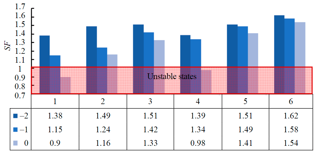
Fig.5. Histogram of SF dependence on the distance to the disturbance (−2; −1; 0 m) with different parameters of the face support
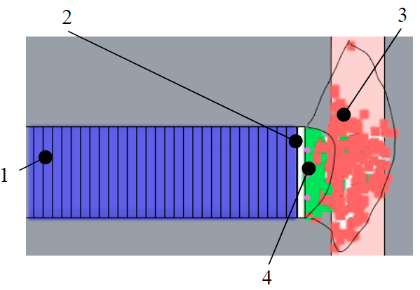
Fig.6. A fragment of the model at the stage of static balance 1 – tunnel lining; 2 – construction of a temporary face support; 3 – areas of exceeding the maximum shear stresses on the site; 4 – areas of exceeding the maximum tensile stresses
The relatively small volume of the first collapse is associated with exceeding the tensile stress limits. This is confirmed by the visualization of individual areas in the calculation model in which the tensile strength has been exceeded (green dots in Fig.6). Tangential stresses contribute more to the further collapse of soils. The red color in Fig.6 shows the points at which the maximum shear stresses at the sites are exceeded. At the same time, the picture of the visualized regions of the limit state may have larger geometric parameters than on the displacement isofields. This is due to the involvement of not the entire volume in the processes of active movement.
Thus, the flexural stiffness of the temporary timbering of the face affects the state of stability in the face. Regardless of the method of timbering the face soils, tangential stresses and angular plastic deformations of shape change accumulate on disturbed soils. When the face approaches the zone of disturbed soils in scenarios of lack of support or insufficient resistance (less than 2.23 kPa) from the side of the support in the face soils, the strength criterion for tensile stresses and shear stresses is not met.
Discussion
For a comparative analysis, the case of the rockfall formation of the soil in the face of the transition corridor of the interchange node of the station “Vladimirskaya-2” under construction from the operating station “Vladimirskaya”, which occurred in October 1989, was considered. “On October 21, 1989, the 4th bunton suddenly caved in and was squeezed out, the rock fell out of the face with a volume of 10-15 m3. An hour later, a rockfall from the roof of the face with a volume of about 2 m3 occurred again, and after another rockfall, all the roof fastening, the face and the filling were demolished. In the roof above the 6th ring of the lining, a dome with a height of up to 7 m with a volume of 170 m3 was formed” [30]. The experience of measuring loads on the structure of the leading support of an underground structure is described in [40]: “The load on the support from the rock pressure on the 60th day was 110 kPa”, which for the conditions under consideration is equivalent to a pressure of 0.1 γN. The distributed pressure from the weight of the rocks collapsed in the “Vladimirskaya-2” face over the face area is about 80 kPa, which is less than recorded in the study [43]. Despite the fact that the loads were less than expected, the collapse that occurred destroyed the face support and exposed structures on the surface to the risk of excessive displacements.
Thus, the calculations made it possible to describe the collapse that occurred in 1989. At the same time, there is a qualitative convergence of the assumed parameters of the collapse. The numerical value may differ due to the lack of data on engineering and geological parameters at the construction site.
Conclusion
Using the proposed spatial elastic-plastic model with strengthening, a prediction of the stress-strain state in the rock mass of disturbed soils was made. Based on the criteria of stability and loading capacity, a forecast of rockfall in the face zone of the tunnel is made. The spatial outlines of the rockfalls and their dimensions have been established, which are the theoretical basis for calculating vertical loads on the temporary support of the face in the disturbed zone.
Numerical experiments on spatial elastic-plastic models have revealed the mechanism and patterns of formation of zones of the limiting state as they approach the zone of disturbed soils. Zones of excess tensile stresses develop on the face surface and a sliding surface is formed.
Modeling of finite stiffness elements showed the dynamics of changes in stability and the SF parameter for various design scenarios of the face entering the disturbance zone. The analysis of the obtained dependencies showed that the largest value of SF is characteristic of the undisturbed soil area, and the decrease in the SF parameter occurs as it approaches the disturbance zone in all design scenarios with different dynamics.
The use of the method of iterative reduction of strength parameters in assessing the stability of the tunnel face determined the forms of possible loss of stability. When comparing the obtained forms of the rockfall at the “Vladimirskaya-2” station with the data of field observations, a qualitative agreement of the form of the rockfall was established.
A predictive assessment of stability and the form of loss of balance based on an elastic-plastic model with strengthening will make it possible to detail the technological stages of the tunnel, taking into account the stresses historically formed during the previous stages of tunneling. The proposed method for assessing the stability of the tunnel face differs from the known methods by taking into account the volumetric stress state of the disturbed soil mass, the possibility of determining the disturbed zones in the face depending on the action of tensile stresses and limiting states during plastic deformation.
The result of using the proposed method is a qualitatively comparable shape of the spatial outline of the rockfall and the determination of the magnitude of the loads on the temporary support of the face. This makes it possible to calculate the support according to the scheme of the specified loads and consider many design scenarios within the framework of one predictive geomechanical model.
References
- Bakharev T.S., Zhamoyda V.A., Zubarev S.E. et al. Geological Atlas of Saint Petersburg. St. Petersburg: Komilfo, 2009, p. 57 (in Russian).
- Dashko R.E., Aleksandrova O.Yu., Kotyukov P.V., Shidlovskaya A.V. Features of engineering and geological conditions of Saint Petersburg. Razvitie gorodov i geotekhnicheskoe stroitelstvo. 2011. N 1, p. 1-47 (in Russian).
- Lunardi P. Design and construction of tunnels: Analysis of controlled deformation in rocks and soils (ADECO-RS). Design and Construction of Tunnels: Analysis of Controlled Deformation in Rocks and Soils (ADECO-RS). Leipzig: Springer, 2008, p. 577. DOI: 10.1007/978-3-540-73875-6
- Michalowski R.L., Drescher A. Three-dimensional stability of slopes and excavations. Geotechnique. 2009. Vol. 59. Iss. 10, p. 839-850. DOI: 10.1680/geot.8.P.136
- Dashko R.E., Vlasov D.Yu., Shidlovskaya A.V. Geotechnics and underground microbiota. St. Petersburg: Institut “PI Georekonstruktsiya”, 2014, p. 280 (in Russian).
- Dashko R.E., Shidlovskaya A.V., Pankratova K.V., Zhukova A.M. Technogenic transformation of the basic components of megacities underground space and its account in geomechanical calculations (on the example of Saint Petersburg). Journal of Mining Institute. 2011. Vol. 190, p. 65-70 (in Russian).
- Vlasov S.N., Makovskiy L.V., Merkin V.E. Emergency situations during the construction and operation of transport tunnels and subways. Moscow: “TIMR”, 2000, p. 201 (in Russian).
- Anagnostou G. The contribution of horizontal arching to tunnel face stability. Geotechnik. 2012. Vol. 35. Iss. 1, p. 34-44. DOI: 10.1002/gete.201100024
- Peila D. A theoretical study of reinforcement influence on the stability of a tunnel face. Geotechnical and Geological Engineering. 1994. Vol. 12. Iss. 3, p. 145-168. DOI: 10.1007/BF00426984
- Sitarenios P., Kallivokas G., Prountzopoulos G. et al. Investigation of tunnel face stability and deformation using critical state plasticity. Tunnelling in a challenging environement: Proceedings of the 2nd Eastern European Tunnelling Conference. 2014. Vol. 47, p. 182-192. DOI: 10.1016/j.tust.2014.12.014
- Protosenya A.G., Iovlev G.A. Prediction of the stress-strain state in the vicinity of an underground structure in non-linearly deformable soil masses. Izvestiya Tul'skogo gosudarstvennogo universiteta. Nauki o Zemle. 2020. N 2, p. 215-227 (in Russian).
- Chakeri H., Ozcelik Y., Unver B. Effects of important factors on surface settlement prediction for metro tunnel excavated by EPB. Tunnelling and Underground Space Technology. 2013. Vol. 36, p. 14-23. DOI: 10.1016/j.tust.2013.02.002
- Protosenya A.G., Belyakov N.A., Do N.T. The development of prediction method of earth-pressure balance and earth surface settlement during tunneling with mechanized tunnel boring machines. Journal of Mining Institute. 2015. Vol. 211, p. 53-62 (in Russian).
- Broere W. Tunnel face stability & new CPT applications: Doctoral thesis. Amsterdam: Delft Unin, 2001, p. 208.
- Eshraghi A., Zare S. Face Stability Evaluation of a TBM-Driven Tunnel in Heterogeneous Soil Using a Probabilistic Approach. International Journal of Geomechanics. 2014. Vol. 15. Iss. 6. N 04014095. DOI: 10.1061/(asce)gm.1943-5622.0000452
- Jia-hua Zhang, Wei-jun Wang, Dao-bing Zhang et al. Safe range of retaining pressure for three-dimensional face of pressurized tunnels based on limit analysis and reliability method. KSCE Journal of Civil Engineering. 2018. Vol. 22. Iss. 11, p. 4645-4656. DOI: 10.1007/s12205-017-0619-5
- Mollon G., Dias D., Soubra A. Probabilistic Analysis of Circular Tunnels in Homogeneous Soil Using Response Surface Methodology. Journal of geotechnical and geoenvironmental engineering. 2009. Vol. 135. Iss. 9, p. 1314-1325. DOI: 10.1061/(ASCE)GT.1943-5606.0000060
- Prountzopoulos G. Investigation of the excavation face stability in shallow tunnels: Doctoral thesis. Athens, 2012, p. 452.
- Mustafin M., Bykasov D. Adjustment of Planned Surveying and Geodetic Networks Using Second-Order Nonlinear Programming Methods. Computation. 2021. Vol. 9. N 13, p. 1-17. DOI: 10.3390/computation9120131
- Karasev M.A. Tunnel induced deformation of strata and formation of surface settlement trought during construction process. Journal of Mining Institute. 2011. Vol. 190, p. 163-170 (in Russian).
- Kavvadas M., Prountzopoulos G., Tzivakos K. Prediction of Face Stability in Unsupported Tunnels using 3D Finite Element Analyses. 2nd International Conference on Computational Methods in Tunnelling (EURO, TUN 2009), 9-11 September 2009, Bochum, Germany. Bochum: Aedificatio Publishers, 2009, p. 1-4.
- Trushko V.L., Shokov A.N. Geomechanical substantiation of stability of the tunnel’s face which situated in the proterozoic clay’s. Journal of Mining Institute. 2012. Vol. 195, p. 146-148 (in Russian).
- Anagnostou G., Schuerch R. Tunnel face stability and tunnelling induced settlements under transient conditions: Technical report. Zurich, 2016, p. 181.
- Vermeer P.A., Ruse N., Marcher T. Tunnel heading stability in drained ground. Felsbau. 2002. Vol. 20. N 6, p. 8-18.
- Belyakov N.A., Karasev M.A. Analysis of the influence of the advanced timbering of the tunnel face with anchors on the development of geomechanical processes in the rock mass. Perspektivy razvitiya inzhenernykh izyskaniy v stroitel'stve v Rossiyskoy Federatsii. Moscow: Akademicheskaya nauka, 2015, p. 120-127. (in Russian).
- Lebedev M.O., Karasev M.A., Beliakov N.A. The Influence of the Front of the Tunnel Face Support on the Development of Geomechanical Processes at Rock Massif. Izvestiya vysshikh uchebnykh zavedenii. Gornyi zhurnal. 2016. N 3, p. 24-32 (in Russian).
- Lebedev M.O. Patent N 2723422 RF. The method of timbering the tunnel face. Publ. 11.06.20. Bul. N 17 (in Russian).
- Oreste P. Evaluation of the tunnel face stability through a ground stress analysis with a hemispherical geometry approximation. American Journal of Applied Sciences. 2014. Vol. 12. N 11, p. 1995-2003. DOI: 10.3844/ajassp.2014.1995.2003
- Broms B.B., Bennermark H. Stability of clay at vertical openings. Journal of Soil Mechanics & Foundations Division. 1967. Vol. 93. Iss. 1, p. 71-94. DOI: 10.1061/JSFEAQ.0000946
- Vlasov S.N., Makovskij L.V., Merkin V.E. Accidents in transportation and subway tunnels – construction and operation. Moscow: Elex-KM Publishers, 2001. p. 200.
- Cherdantsev N.V. Geomechanical Conditions of Surrounding Rocks Around Excavation and Geological Dislocation. Mining informational and analytical bulletin. 2015. N 12, p. 52-58.
- Cherdantsev N.V. Anisotropic Rock Massif State around the Mine Opening Headed Near a Disjunctive Disturbance Research. Promyshlennaya bezopasnost' i geomekhanika. 2017. N 2, p. 34-40 (in Russian).
- Senent S., Jimenez R. A tunnel face failure mechanism for layered ground, considering the possibility of partial collapse. Tunnelling and Underground Space Technology. 2015. Vol. 47, p. 182-192. DOI: 10.1016/J.TUST.2014.12.014
- Oreste P. The stability of the excavation face of shallow civil and mining tunnels. Acta Geotechnica Slovenica. 2011. Vol. 8. N 2, p. 57-65.
- Annin B.D., Korobeynikov S.N. Methods of elasticity and plasticity theory in rock mechanics and geodynamics. Ecological Bulletin of Research Centers of the Black Sea Economic Cooperation. 2012. Vol. 9. N 1, p. 9-19 (in Russian).
- Lunardi, P., Bindi R. The evolution of reinforcement of the advance core using fibre-glass elements. Felsbau. 2004. Vol. 22. N 4, p. 8-19.
- Brinkgreve R.B.J., Bakker H.L. Nonlinear finite element analysis of safety factors. 7th International Conference on Computer Methods and Advances in Geomechanics, 6-10 May 1991, Cairns, Australia. Rotterdam: Balkema, 1991, p. 1117-1122.
- Mirsalimov V.M., Kalantarly N.M. Solution of an Elastoplastic Problem for Rock, Weakened by a Circular Working Under Action of Tectonic and Gravitational Forces. News of the Tula state university. Sciences of Earth. 2021. N 1, p. 207-216 (in Russian).
- Weiping Liu, Shaofeng Wan, Xinqiang Song et al. Face Stability Analysis of Shield Tunnel Using Slip Line Method. Mathematical Problems in Engineering. 2019. Vol. 2019. N 5902837. DOI: 10.1155/2019/5902837
- Pan Q., Dias D. Safety factor assessment of a tunnel face reinforced by horizontal dowels. Engineering Structures. 2017. Vol. 142, p. 56-66. DOI: 10.1016/j.engstruct.2017.03.056
- Hrubesova E., Duris L. Assessment of tunnel’s face support pressure. Building up Efficient and Sustainable Transport Infrastructure 2017 (BESTInfra2017), 21-22 September 2017, Prague, Czech Republic. IOP Conference Series: Materials Science and Engineering, 2017. Vol. 236. N 012074. DOI: 10.1088/1757-899X/236/1/012074
- Kaihang Han, Chengping Zhang, Wei Li,Caixia Guo. Face Stability Analysis of Shield Tunnels in Homogeneous Soil Overlaid by Multilayered Cohesive-Frictional Soils. Mathematical Problems in Engineering. Vol. 2016. N 1378274. DOI: 10.1155/2016/1378274
- Maslak V.A. Experience in providing the stability of tunnel face and roof during its drivage in proterozoic clays. Journal of Mining Institute. 2009. Vol. 183, p. 297-299 (in Russian).