Method of drilling process control and experimental studies of resistance forces during bits drilling with PDC cutters
- 1 — Ph.D., Dr.Sci. professor Siberian Federal University
- 2 — Ph.D. Senior Teacher Siberian Federal University
- 3 — ASSISTANT Siberian Federal University
- 4 — Ph.D. docent Siberian Federal University
- 5 — Jilin University

Abstract
A rational, theoretically proved and empirically verified control system is a condition for optimal management of the drilling process in compliance with the criteria for minimizing the cost of time and material resources. A new generation of rock-cutting tools using PDC cutters (polycrystalline diamante cutters), which are extremely effective when drilling wells for various purposes in medium-hard rocks, dictates the need to develop methods and criteria for optimal control of the drilling process using this tool. The paper presents an analysis of the force interaction between rock-cutting elements, face rock, and drilling mud saturated with slam, highlights the influencing factors and provides dependencies for determining the parameters of rock failure. Empirical verification of the theoretical propositions was carried out based on the data analysis from experimental bit drilling of marble with PDC cutters with a diameter of 76.2 mm, processed using the method of full factor experiment to obtain mathematical models of factors and their graphical interpretation. The method of controlling the drilling process based on the optimal ratio of the tool rotation frequency, axial weight and deepening per one turnover is considered, which allows determining the rock failure mode at the well bottom by indirect signs and choose the optimal values of the drilling mode parameters that correspond to the most optimal conditions in terms of achieving the maximum mechanical drilling speed in conjunction with the rational mode of rock-cutting tool operation. A scheme is presented that contains possible variants of the bit run mode and ways to recognize them by the ratio of the deepening per turnover and the rotation frequency of the rock-cutting tool.
None
Introduction. The PDC cutters use as a rock – cutting elements for the crowns and bits production is one of the most progressive trends in the production of rock-cutting tools for rock failure [2, 8 - 14]. This type of tool is able to provide high drilling speeds for various purposes in rocks of a wide range of hardness, combined with a large resource. However, the issue of force interaction between rock-cutting elements, rock containing the face, and drilling mud saturated with slam, can not be called thoroughly studied.
Resistance forces when drilling with PDC-cutter bits significantly affect the fracture process, its efficiency, and, in particular, the cutters resistance themselves [7]. The studies presented in [5], and also Smith Bits analytical data [15] shows that the most intensive cutters wear is possible at the point distance of 0.8 of the r bit radius, indicating that the main influence on the cutters wear of resistance force to the cutters work, the size of which is determined by the value of the linear cutters speed, which increases from the end face center to its periphery in accordance with the 2πωr, where ω is the rotation frequency of the bit. K.I.Borisov's research is devoted to the in-fluence of the cutter movement speed in the process of cutting and chipping rocks on the rock failure process [1].
The dependence from the work [1], showing the relationship between the resistance coefficient to rock failure from the axial weight value on the cutter, obtained during experimental studies on the stand is known. It follows from the dependence that the resistance coefficient actively increases at the stage of elastic rock deformation, decreasing at the moment when the stresses in the rock cause active bulk failure and irreversible plastic deformation (crack formation, active failure), as evidenced by the values of the angle α obtained in the range of small (elastic deformation zone) and more significant (plastic deformation zone) values of the axial weight. It should be noted that the curve presented in this paper does not take into account the resistance of the environment, namely, drilling mud and the resistance of already destroyed rock before the cutter, but not yet removed from the well bottom.
Research methodology. Consider the theoretical propositions that allow to take into account the resistance of both rock already destroyed before the cutter, and the resistance of the environment (sample mud) when drilling with PDC cutter bits. To clarify the acting forces and reactions, we refer to the diagram (Fig.1).

The force that pushes out a cutter with a negative front angle in the process of cutting-chipping rock can be determined by the formula
where σsk – is the ultimate resistance on shear rocks, PA; Ssk – is the site chipped by cutter rock on the front face, m2 ; K – coefficient taking into account the excess rock resistance force to cutting-chipping with increasing the linear cutter speed.
The site size Ssk chipped by cutter rock is defined in [3]:
where d – is the cutter diameter, m; h – the penetration depth of the cutter into the rock, m; γsk – chipping angle of the rocks on the cutter front face, deg.
The completed formula (1) would read as follows:
The resistance of the environment can be calculated by taking into account, first of all, the cutter movement speed and the density of the environment:
where ρs – the weight density of the environment taking into account the density of drilling mud saturated with slam from the destruction zone and failure rocks H/m3 ; S – cutter area or its projection on the cut line, if the cutting angle φs is not zero, and makes an angle of more than 0 degrees (usually not more than 5-10°); Cs – resistance coefficient on the part of the cutter is determined by the shape of its plane (approximately for a flat 1, for a round convex 0.5, for a concave circle 1.5).
Thus, the total resistance force moving along the cutter face is equal to the sum of Rv and Rs.
From the presented scheme (Fig.1), it follows that the reaction of the not yet destroyed rock Rv affects the compression core (compaction) 1, since in the compression core it is destroyed to the fine crushing state. The reaction Rv in the case of a steady – state cutting-chipping mode of rock is directed towards the resulting vector of axial weight and cutting – chipping force R and at right angles to the cutter surface.
The force that is directed towards the axial weight, compensating the resistance force Rv, will be equal
where γp – is the front angle of the cutter, deg.
The resistance of the environment causes the appearance of the Fn reaction, directed towards the axial weight and producing the effect of pushing the cutter out of the rock during the bit turnover and the rocks failure. This reaction can be determined from the dependence
To determine the coefficient K in formulas (1) and (3), we should use the results of experimental studies to determine the increasing resistance to cutting – chipping of rock with an increase the linear cutter speed, presented in [3], where the dependences reflecting the influence of the cutting and chipping speed of rock vr on the amount of force Rv for sandstone are given.
From formula (3) follows that the force Rv in the steady-state cutting – chipping mode of rock, when all the main parameters included in the formula remain unchanged, the change in the cutter movement speed will depend on the value of the rock stress on chipping σsk. The rock strength parameter σsk will also increase with increasing cutting and chipping speed vr In this case, the coefficient K, represented in formula (3) will be equal to
where Rvt – the resistance force corresponding to the value of the linear cutter speed; Rvn – is the resistance force corresponding to the linear speed close to zero.
The Rvt force can be determined from the dependence
where θ is the tilt angle of the experimental curve that can be obtained when testing the ultimate resistance on shear of a certain rock; x – is the current relative value of the distance from the end face center of the bit to the point where the determination of Rv; r – is the bit radius.
Thus, for a successful estimation of the parameter K, it is sufficient to have an experimentally determined dependence of the cutting – chipping resistance, namely, the angle β, obtained from the growth line of the parameter Rv.
Discussion. For an empirical evaluation of the obtained resistance calculation values, consider the data of experimental bit drilling of marble with PDC cutters with the diameter of 76.2 mm.
As a result of drilling according to the full factor experiment plan with two influencing factors (axial weight and rotation frequency) [4] the following models were obtained that reflect the drilling process from various positions, taking into account both the penetration rate and tool life, and the amount of deepening per turnover – the most important parameter of drilling management,
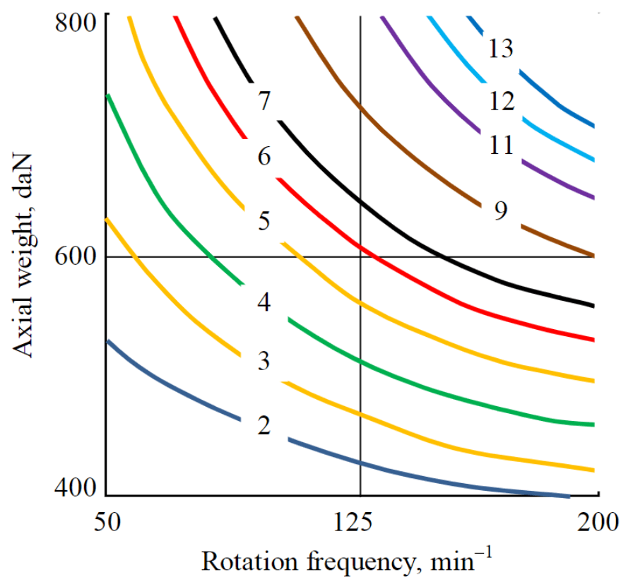
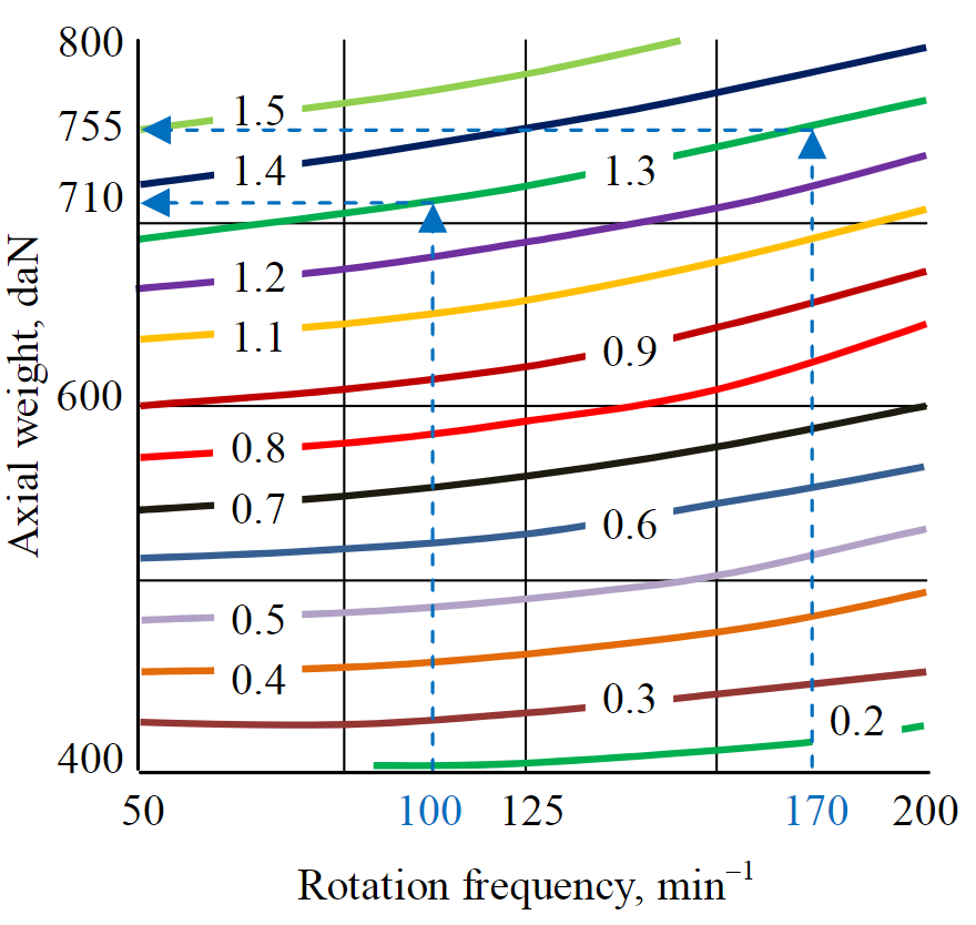

Fig.2 shows a graphical interpretation of mechanical drilling speed (9) models within the limits used in the experiment of the axial weight Р and rotation frequency ω.
Fig.3 shows a graphical interpretation of the deepening model per one turnover (10). The rational area of drilling modes control, revealed by the analysis of energy intensity (model (12), shows that the deepening at the level of 1.3-1.4 mm/Rev will be effective, which will provide almost the highest mechanical drilling speed in the experimental conditions.
Processing of the obtained data, in particular graphs of the mechanical drilling speed, allows to obtain graphical dependences of the deepening per turnover on the axial weight value (Fig.3) and the rotation frequency (Fig.4).
The dependencies in Fig.4 according to the graphs of the mechanical drilling speed (see Fig.2) at the minimum, average and maximum rotation frequency to the dependence hrev = vm/ω in accordance with the method from [4] is obtained. Shown in Fig.4 graphic dependences indicate an increase in the axial weight with an increase in the deepening value per turnover, while the lines of the deepening per turnover have an intersection Рос = 455 daN. axial weight of this value divides the failure process into a fatigue-surface mode (up to 455 daN) and a bulk failure (after 455 daN).
The failure mode also changes the dependence of the deepening on the rotation frequency per turnover:
– – in case of fatigue-surface failure, when the axial weight (stresses in the rock) is not sufficient for bulk failure, the maximum deepening h1 is observed at the maximum rotation frequency (200 min-1), and the minimum deepening h3 at the minimum rotation frequency (50 min-1);
– – in case of bulk failure, the situation is reversed, i.e. the maximum value of the deepening h1 corresponds to the lowest value of the rotation frequency (50 min-1), the minimum deepening h3 corresponds to the maximum rotation frequency (200 min-1).
Fig.5 presents graphs showing the dependence of the deepening value per turnover on the rotation frequency at the values of the axial weight of 330 daN in the fatigue-surface failure mode and 600, 750 and 800 daN in the bulk failure mode of the rock. The presented data show an increase in the deepening per turnover during fatigue-surface failure (line 1 in Fig.5) as the rotation frequency of the drilling tool increases. At the same time, in the case of bulk failure, by the contrast, there is a decrease in the deepening per turnover as the rotation frequency increases (lines 2, 3, 4 in Fig.5), which indicates an increase in resistance from the rock and the environment as the linear cutting – chipping speed increases. In doing so, the rate of decrease in the depth of cutting-chipping rock increases with an increase in the axial weight and, respectively, the cutters penetration depth into the rock.
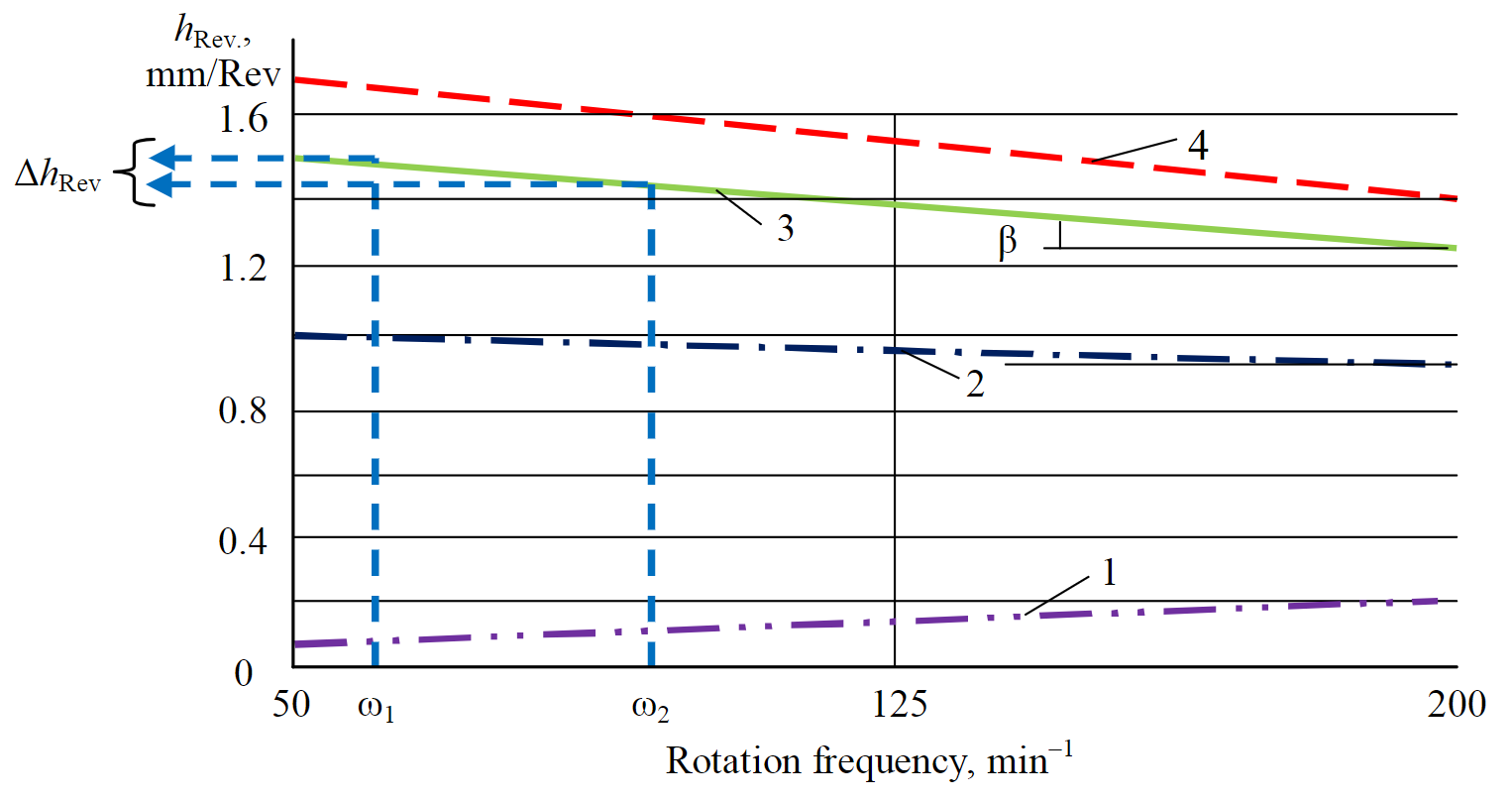
The rate of decrease in the deepening per turnover, expressed in terms of the angle β, allows to determine the resistance coefficient as the tangent of this angle:
where Δh – is the value of the decrease in the deepening per turnover in the interval of increasing the rotation frequency Δω, for example, from ω1 to ω2 ((Fig.5).
The presented results of experimental drilling processing data show that the obtained theoretical dependences have been confirmed, since they indicate that as the deepening of cutter penetration into the rock h increases, the resistance increases in the bulk failure mode, and in the fatigue-surface failure mode, on the contrary, decreases. It is related to the fact that in the fatigue-surface failure mode, the maximum deepening per turnover is achieved at the maximum rotation frequency, which is confirmed by many experimental data [4,6].
Results. The practical application of the obtained regularities can be implemented in the diagnostics of the rock failure mode when controlling the drilling process using interactive systems, for example, bottom-hole telemetry systems or drilling process control using APS computer support systems [4].
Fig.6 shows the program for managing the drilling mode parameters. For example, at stage I, the rotation frequency increased from the value of ω1 to ω2 with the constant axial weight (500 daN). In this case, there is a decrease in the deepening value per turnover due to the growth of resistance forces from the destroyed rock and environment (formulas (3) and (4), which generates the appearance of forces that reduce the value of the axial weight (formulas (5) and (6). In this case, the mechanical speed will be determined by the product vm = h1ω2. Since there was a decrease in the depth value from hо до h,1 the growth of vm will be insignificant or absent.
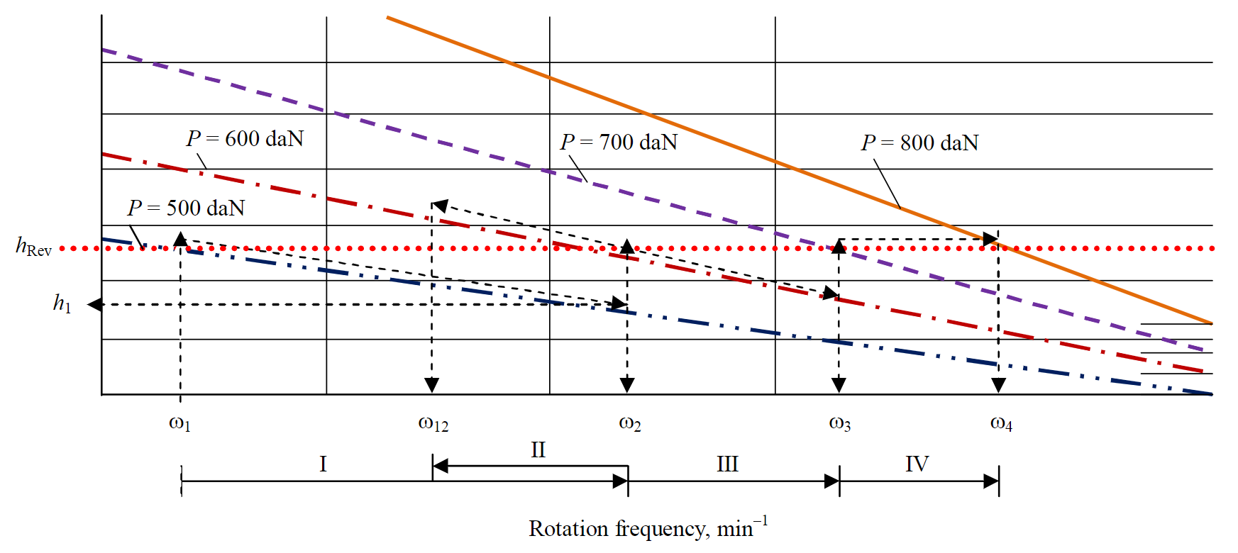
To solve this problem, we can proceed to the implementation of stage II, which consists in increasing the axial weight to 600 daN and reducing the rotation frequency to the value of ω12, which will provide a higher value of the mechanical drilling speed compared to stage I with a lower value of the rotation frequency of the drilling tool.
It is rational to work out the drilling tool according to a given deepening value per turnover, for example, hrev (Fig.6). In this case, rotation frequency corrections, for example, from ω2 to ω3 and ω4, will require changes in the axial weight, namely, from the axial weight value 600 to 700, and then 800 daN, which will allow to gradually increase the mechanical drilling speed as the rotation frequency increases.
To determine the most optimal ratio between the selected rotation frequency and the axial weight in the interactive drilling process control mode, empirical models of the type (10) and the corresponding graphical interpretation of the model can be used (see Fig.3). For example, if the set value for working out the bit is a deepening of 1.3 mm per turnover hrev, р(see Fig.3), then changing the rotation frequency from 100 to 170 min-1 will require an increase in the axial weight from 710 to 755 daN, which will preserve the value of the deepening of 1.3 mm and increase the mechanical speed from 7.8 to 13.3 m/h.
Such empirical models obtained in interactive mode and their interpretation allow to quickly manage drilling modes in the area that ensures rational development of bits.
When working out a drilling tool, the most optimal mode is the bulk failure of rock. However, in the working out process over a long interval, when there is a change of different drillability degrees of rocks, the wear of the bit armament occurs, the volume of generated mud and the conditions for cleaning the face from the drilled rock, the amount of cleaning agent supplied to the face, and the drilling mode may change, deviating from the favorable bulk failure mode of rock to the less effective fatigue-surface failure mode.
For example, during bit wear or when soft rock changes to harder rock, the failure mode may become fatigue-surface. The variant of face slamming with insufficient flushing is possible, or on the contrary, it may happen that the excessive supply of drilling mud will lead to the hydraulic support of the bit end part, or the case of bit armament overheating may cause its active thermomechanical destruction.
Interactive support for bit development in each of these cases, taking into account the established relationships between the bit deepening per turnover at the bottom hole and the parameters of the drilling mode, allows for timely and optimal adjustment of the conditions for bit development.
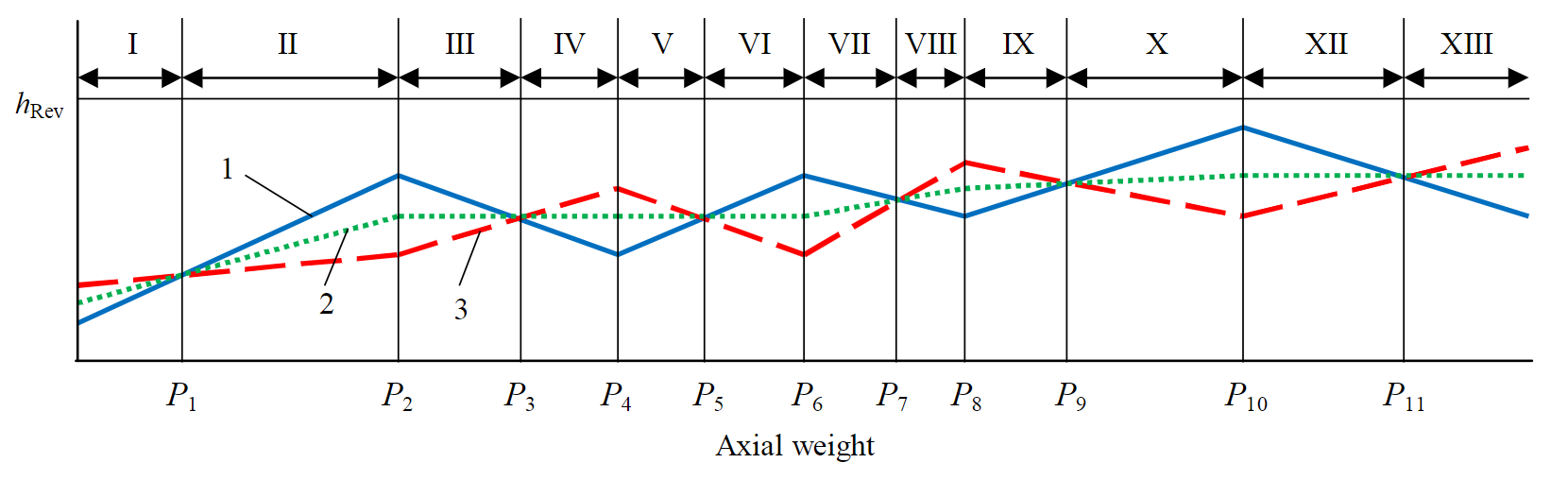
Figure 7 shows a diagram containing possible variants of the bit development mode and ways to recognize them by the ratio of the deepening per turnover and the bit rotation frequency.
When working out the bit, the following tool operation modes may occur with some alternation:
• I – fatigue-surface failure;
• II – bulk failure;
• III – the return to fatigue-surface failure, can be caused by increased rock hardness, slamming of the face, wear of the bit armament, hydraulic support of the bit by the flow of sample mud;
• IV – fatigue-surface failure, can be caused by increased rock hardness, slamming of the face, wear of the bit armament, hydraulic support of the bit by the flow of sample mud;
• V – return to bulk failure;
• VI – bulk failure at a new level of axial weight;
• VII, VIII – the repetition of modes III, IV;
• IX, X – return to bulk failure and bulk failure at a new level of axial weight;
• XII, XIII – transition and mode of thermomechanical failure of drilling tools under excessive axial weight (in many respects similar to modes III, IV).
Conclusion. Thus, taking into account the theoretical principles and examples of practical testing methods of process control of drilling bits with PDC cutters, considering the resistance forces during the drilling, it makes possible to automate the process using the proposed method for the presented algorithm of optimal process conditions based on three main criteria (rotation frequency, axial weight, and deepening per turnover of the drilling tool), taking into account real-time information about the process.
In addition to process control in the optimal range of values of the process parameters, using the drill bits development method with the use of empirical models of interactive controlling the drilling process, it is possible to recognize well bottom situation and control the settings for both exiting adverse drilling conditions, and for selecting of optimum mode parameters when working out the bits for a given size of the deepening per one turnover of the tool on the well bottom.
The method of drilling process control presented in the article can be used when drilling wells for both solid minerals and oil and gas of relatively small length (up to 1000-1500 m), due to the fact that with more significant values of the drilled wells depth, the influence of destructive factors on the management process increases, such as increasing rock pressure, which affects the physical and mechanical properties of the drilled rocks. The long length of the drill string, combined with the possible complexity of the well profile, leads to increased power losses due to the string friction and the occurrence of oscillatory processes, which negatively affects the transfer of axial weight and rotation frequency to the bit from the wellhead.
References
- Borisov K.I. Modern methods for evaluating rock resistance to cutting and chipping when drilling with PDC bits. Tomsk: Iz-vo TPU, 2013, p. 166 (in Russian).
- Litvinenko V.S., Dvoinikov M.V. Justification of the Technological Parameters Choice for Well Drilling by Rotary Steerable Systems. Journal of Mining Institute. 2019. Vol. 235, p. 24-29. DOI: 10.31897/PMI.2019.1.24 (in Russian).
- Neskoromnykh V.V., Borisov K.I. Analytical study of the cutting-chipping rock process with PDC cutters bits. Izvestiya Tomskogo politekhnicheskogo universiteta. 2013. Vol. 323. N 1, p. 191-195 (in Russian).
- Neskoromnykh V.V. Optimization in exploration production. Krasnoyarsk: Sibirskii federalnyi universitet, 2013, p. 246 (in Russian).
- Neskoromnyh V.V., Popova M.S., Golovchenko A.E. Use of the New Generation Material as Elements of Modern Rock Cutting Tools. Construction of Oil and Gas Wells on Land and Sea. 2019. N 10, p. 15-20. DOI: 10.30713/0130-3872-2019-10-15-20 (in Russian)
- Neskoromnyh V.V., Pushmin P.S. Methods to Determine Optimum Parameters of the Mode and Conditions of Borehole. Iz-vestija Sibirskogo otdelenija Sekcii nauk o Zemle RAEN. 2011. N 1 (38), p. 151-157 (in Russian).
- Tretyak A.Ya., Popov V.V., Grossu A.N., Borisov K.A. Innovative approaches to the design of highly efficient rock cutting tools. Gornyi informatsionno-analiticheskii byulleten. 2017. N 8, p. 225-230. DOI: 10.25018/0236-1493-2017-8-0-225-230 (in Russian).
- Brook B. Principles of diamond tool technology for sawing rock. International Journal of Rock Mechanics and Mining Sci-ences. 2002. Vol. 39. Iss. 1, p. 41-58. DOI: 10.1016/S1365-1609(02)00007-2
- Hasan A.R., Kabir S. Wellbore heat-transfer modeling and applications. Journal of Petroleum Science and Engineering. 2012. Vol. 86-87, р. 127-136. DOI: 10.1016/S.petrol.2012.03.021
- Huang H., Lecampion B., Detournay E. Discrete element modeling of tool-rock interaction I: Rock cutting. International Journal for Numerical and Analytical Methods in Geomechanics. 2013. Vol. 37. Iss. 13, p. 1913-1929. DOI: 10.1002/nag.2113
- Aslaksen H., Annand M., Duncan R., Fjaere A., Paez L., Tran U. Integrated FEA modeling offers system approach to drillstring optimization. Society of Petroleum Engineers. SPE Drilling Conference. 2006. 21-23 February. Miami, Florida, USA, p. 669-684. DOI: 10.2118/99018-MS
- Litvinenko V.S. (ed). XVIII International Coal Preparation Congress: Saint-Petersburg, Russia, 28 June – 01 July 2016. Springer International Publishing, 2016. Vol. 1, p.1196. DOI: 10.1007/978-3-319-40943-6
- Ai Z., Han Y., Kuang Y., Wang Y., Zhang M. Optimization model for polycrystalline diamond compact bits based on reverse design. Advances in Mechanical Engineering. 2018. Vol. 10. Iss. 6. DOI: 10.1177/1687814018781494
- Zanevskii O.A., Ivakhnenko S.A., Ilnitskaya G.D., Zakora A.P., Bogdanov R.K., Karakozov A.A., Popova M.C. Production of coarse-grained high-strength microgrits to be used in drilling tools. Journal of Superhard Materials. 2015. Vol. 37. Iss. 2, p. 85-96. DOI: 10.3103/S1063457615020082
- Product Catalog. Smith Bits. A Schlumberger Company. 17_BDT_310907 Copyright 2018 Schlumberger. All rights re-served. URL: https://www.slb.com/_/media/files/smith/catalogs/bits_catalog (дата обращения 10.04.2020).