
Method for calculating dynamic loads and energy consumption of a sucker rod installation with an automatic balancing system
- 1 — Dr.Habil. Professor Ufa State Petroleum Technological University
- 2 — Ph.D. Docent Ufa State Petroleum Technological University
- 3 — Assistant Lecturer Ufa State Petroleum Technological University

Abstract
The efficiency of sucker rod pump installations, which have become widespread in mechanized lift practice, is largely determined by the balance of the drive. During the operation of sucker rod installations, the balance of loads acting on the rod string and the drive can change significantly due to changes in the dynamic fluid level, which leads to a decrease in balance and an increase in loads on the pumping equipment units. The increase and decrease in the dynamic level in accordance with the pumping and accumulation cycle occurs in wells operating in the periodic pumping mode. It is shown that during the operation of equipment in a periodic mode, fluctuations in the dynamic level and, accordingly, in the loads acting on the nodes occur. This leads to the need for dynamic adjustment of the balancing weights to ensure the balance of the pumping unit. A system for automatic balancing of the rod drive has been developed, including a balancing counterweight, an electric motor that moves the load along the balance beam, a propeller and a computing unit. To study the effectiveness of the proposed device, a complex mathematical model of the joint operation of the reservoir - well - sucker rod pump - rod string – pumping unit has been developed. It is shown that due to the dynamic adjustment of the balance counterweight position, the automatic balancing system makes it possible to significantly reduce the amplitude value of the torque on the crank shaft (in comparison with the traditional rod installation) and provide a more uniform load of the electric motor. Equalization of torque and motor load reduces the power consumption of the unit.
None
Introduction. Low production wells operated by sucker rod pump units (SRPU) make up a significant share of the production fund. Due to their large number, ensuring the optimal operating mode for these categories of wells is of great importance in terms of labor and economic costs, which largely determine the profitability of field development. In this regard, an urgent task is to improve the applied methods of artificial lift and the development of technical means aimed at maintaining optimal operating conditions for pumping equipment [17, 20].
The efficiency of the sucker rod installations largely depends on the balance of the drive – the pumping unit (PU). In particular, insufficient balance of the drive is the reason for the occurrence of cyclic variable loads of large amplitude, acting on the units of the pumping unit and causing increased wear of its elements. In addition, due to insufficient balance, the amplitude of the torque on the crank shaft increases significantly, and, consequently, the maximum torque generated by the electric motor, increases the degree of unevenness of its load, which leads to a decrease in the efficiency of the engine, an increase in the amount of electricity consumed. Finally, due to the increase in torque, the amplitude of fluctuations in the tension of the drive belts also increases, which causes intensive stretching of the belts and decrease in their service life, slipping of the belts and decrease in the efficiency of the transmission mechanism, and hence the delivery of the pumping unit as a whole. Thus, ensuring optimal balancing of the drive is one of the key tasks of efficient operation of sucker rod installations [7].
Formulation of the problem. Justification of the need to develop a system for automatic balancing of the rod drive. Among the existing methods of balancing pumping units, the most common is mechanical, including balancing (balancing is performed by installing a counterweight on the rear arm of the balancer), crank shaft (counterweights are placed on the crank shaft) and combined (combination of crank shaft and balancing) balancing. The currently used methods for controlling the balance of the PU (current and active power measurement) are based on measuring the current in the stator windings and the voltage on the phases of an induction motor. As a criterion of balance, as a rule, the equality of the amplitude values of the current (current metering) or the power consumption (watt metering) is taken when the balancer moves up and down. The considered methods make it possible to balance the drive directly at the time of measurements with high accuracy. However, during the operation of sucker rod rigs, the balance of loads acting on the rod string and the balancer head can be transformed due to changes in the dynamic fluid level and pressure at the pump intake: in the process of bringing the well to a steady state, when changing the operating mode of the formation or the sucker rod pump. A number of works are devoted to the issues of increasing the energy efficiency of pumping units during pressure fluctuations at their intake [13, 16, 18, 19]. The most significant fluctuations in the dynamic level, according to the pressure at the pump intake, arise when rod rigs operate in a periodic withdrawal mode, and the stock of marginal wells switched to a periodic pumping mode is constantly increasing due to the high degree of depletion of reserves of deposits, and the issues of balancing these wells are becoming even more relevant [6].
In the mode of periodic pumping, fluctuations in the dynamic level are of a cyclical nature: in the half-cycle of accumulation, the pump flow stops, and the liquid level in the annulus increases due to the inflow of fluid from the formation; in the half-cycle of pumping, the dynamic level decreases due to the operation of the pump. The lower boundary of the dynamic level and, accordingly, the minimum value of the pressure at the pump intake are determined from the equation for the balance of fluid inflow from the reservoir and the sucker rod pump supply:
where Qres – reservoir inflow; η – pump flow rate; Kkp – reservoir productivity index; pres – reservoir pressure; pp – pump intake pressure; Δppr – pressure drop from pump intake to reservoir; qT – theoretical supply.
Under the assumption that the inflow of reservoir fluid is proportional to the drawdown to the reservoir, and using the relationship described in [13] to calculate the flow rate, the lower boundary of the inflow pressure can be calculated according to the relationship:
where α, β – empirical coefficients of the dependence of the pump flow rate on the pressure at the pump intake.
In the half-cycle of accumulation, the fluid level in the annulus increases, and the rate of fluid inflow into the well and, accordingly, the rate of rise of the dynamic level ecreases exponentially [8]:
where ρ – fluid density; Hp – pump lowering depth; hmin – lower limit of the dynamic level; corresponding to the minimum intake pressure pmin; t – time; S – cross-sectional area of the annulus.
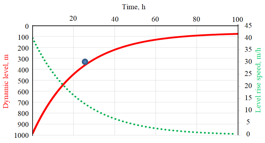
Figure 1 shows the dynamics of fluid level change for a mo¬deled well with the following parameters: reservoir pressure 10 MPa, productivity factor 1 m3/(day∙MPa), reservoir top depth 1100 m, density of pumped fluid 1000 kg/m3, pump run depth 1000 m. The lower limit of the dynamic level is 980 m, the upper limit is 400 m and corresponds to the accumulation time, after which the rate of rise of the level decreases by a factor of e (i.e., the so-called relaxation time – the time period during which the most significant rise of the dynamic level is achieved). In the model example, the accumulation period is 22 h when the dynamic level rises by 600 m.
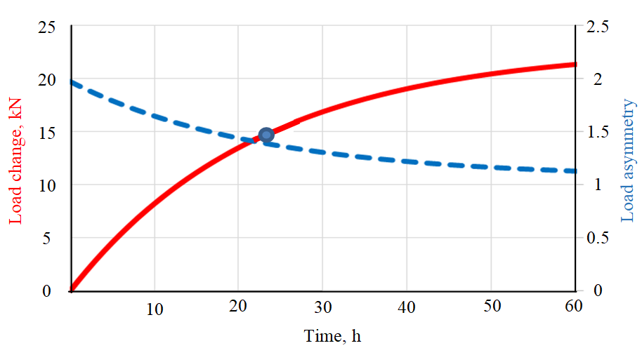
The influence of changes in the dynamic level on the nature of static loads acting in the mechanical chain plunger – rod string – balancer head is shown in Fig.2.
After the accumulation process expires during well start (after 22 hours), the maximum load on the balancer head changes (decreases) by almost 15 kN, while the asymmetry of the loads (the ratio of the maximum load to the minimum) decreases from 2 to 1.4 i.e., by 30 %. A significant change in the nature of the loads acting on the balancer head leads to the need to adjust the balancing weights depending on the position of the dynamic level (to ensure the balance of the pumping unit). Since fluctuations in the dynamic level are of a cyclical nature, it is not possible to permanently adjust the balancing of the pumping unit in manual mode; it is also required to develop mechanisms and systems for automatically balancing the balancing drive of the rod units.
This paper presents the results of a study of the automatic balancing system of the rod drive, which allows in dynamic mode, regardless of the current position of the dynamic level, to ensure the balance of the pumping unit.
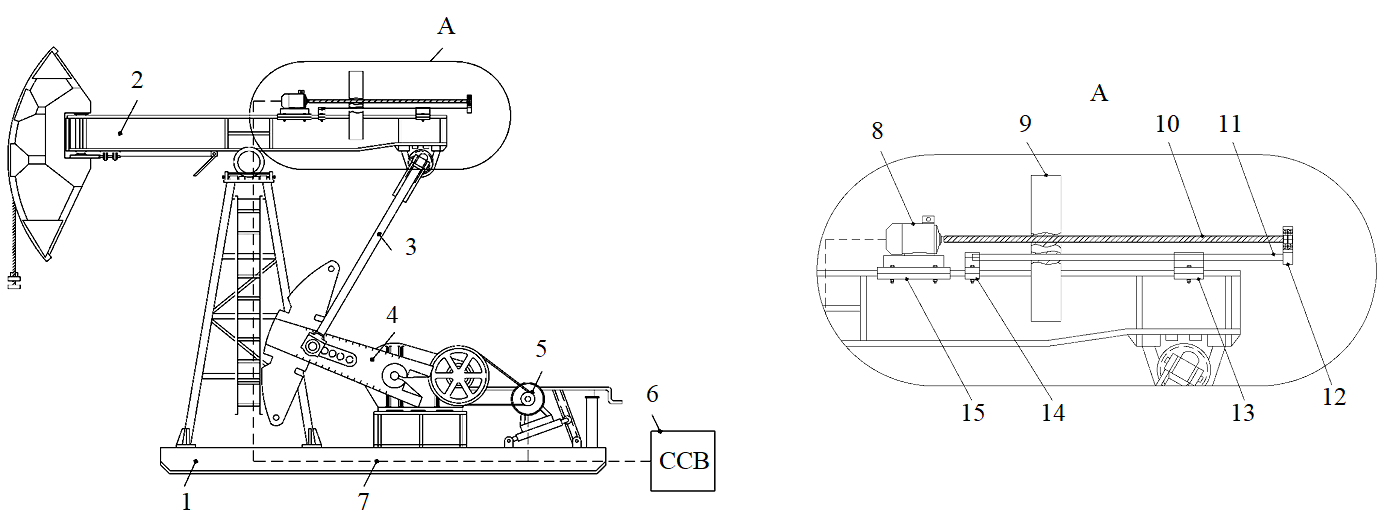
Description of the automatic balancing system and the mathematical model of the operation of the rod pumping unit. To automate the balancing process and increase the reliability of the pumping unit, a system of dynamic balancing of the balancing drive of the rod pumping unit has been developed. Figure 3 shows a general view of a pumping unit with an automatic balancing system.
The balancing system A is made in the form of a balancing counterweight 9, installed on the rear arm of the balancer 2, moving along the balancer by means of a screw 10 on two guide supports 11, and an electric motor 8 that controls the position of the counterweight. In addition, the system contains a computing module 6, which calculates the necessary correction of the balance counterweight position according to the ratio of current amplitudes or power consumption, and then transmits a command to the current distributor that controls the balancing mechanism electric motor 8. The electric motor, in turn, drives the screw 10 rotates in one direction or another, automatically correcting the position of the balancing counterweight [2].
A number of works [4, 5, 9 - 12, 14, 16, 21] are devoted to the study and optimization of the performance indicators of the balancing drive of sucker-rod installations. In articles [3, 10], a mathematical model of a rod installation is presented, which combines analytical dependences for calculating the loads on the balancer head and the torque on the crank shaft. It is shown that the balance of the pumping unit has a significant effect on the value of the maximum torque and its range (the difference between the maximum and minimum torque per swing cycle), the importance of balancing the drive is noted in terms of reducing the maximum torque on the crank shaft and ensuring reliable operation of the gearbox. The authors also proposed a simplified model for calculating the power consumption of a rod installation, based on the assumption of the constancy of the efficiency of the electric motor and drive, regardless of the degree of balance of the pumping unit. Calculations have shown that in a fairly wide range of changes in the position of the balancing weights, the power consumption of the installation changes by less than 5 %. It should be noted that the authors did not take into account the fact that the degree of loading of the electric motor and, accordingly, its efficiency change within each swing cycle, i.e. are variable. The efficiency of the electric motor is largely determined by the shape of the load curve: with an uneven load of the electric motor, due to the unbalance of the pumping unit, the efficiency of the electric motor decreases, which must be taken into account for a correct assessment of the consumed electricity, and the balance of the pumping unit has a significant effect on the consumed electrical power.
In [11, 12] dependences are proposed for calculating the integral efficiency of the operation of an electric motor for a pumping cycle, taking into account the cyclic variable nature of the electric motor load. It is shown that the balance of the pumping unit has a significant effect on the power consumed by the electric motor and the rod installation. It was found that the dependence of electricity losses on the coefficient of imbalance (defined as the relative difference between the maximum power consumption during the movement of the balancer head up and down) is almost linear, and electricity losses due to the imbalance of the PU can reach 10-15 % or more. In work [1] based on the results of field studies, it was found that an insufficient degree of equilibrium of the drive leads to an increase in the consumed electricity by 5-12 %. In particular, it has been shown that in case of insufficient balance in the half-cycle of the downward stroke of the rods, the engine begins to “spin up” due to the weight of the rods and goes into the generator mode, which is expressed in the appearance of negative power. When the engine switches to the generator mode, the mechanical and electrical parts of the engine experience an increased load: the bearings wear out (which can lead to subsequent “runout”), the consumed currents increase, which causes an increase in electrical losses, increased wear of the winding insulation, a decrease in the efficiency of the electric motor.
The significant role of the balance of PU as one of the key factors determining the level of dynamic loads on the machine tool units and the amount of energy consumption for lifting formation fluid is noted in [5, 14]. It is shown that significant loads in the nodes of the crank shaft mechanism, caused, among other things, by an insufficient degree of balance of the drive, are the cause of about 80 % of failures of the ground part of the SRPU equipment. The work also notes the important role of power measuring as the most effective and informative method both from the point of view of ensuring continuous monitoring of the balance of the drive, and from the standpoint of diagnosing the state of ground and downhole pumping equipment. The work [9, 15, 21] is devoted to the study of the solution of direct (recalculation of the watt-meter into a dynamo-gram) and inverse (recalculation of a dynamogram into a power measuring) problems of the dynamics of rod installations. The method including power measuring is undoubtedly one of the most promising methods of instrumental control and diagnostics of the technical condition of rod installations.
It should be noted that, despite the large number of published works, the authors have not investigated the issues of dynamic balancing of rod installations operating in the mode of periodic cyclic changes in the dynamic level and, accordingly, the loads on the plunger, balancer head and drive. To study the effectiveness of the proposed automatic balancing device, a complex mathematical model of the joint operation of the reservoir – well – sucker rod pump – rod string – pumping unit system has been developed. In contrast to existing models, the proposed complex model takes into account the effect of fluctuations in the dynamic fluid level on the value of dynamic loads acting both on the downhole equipment (plunger, rod string) and on the units of the pumping unit (balance beam, crank mechanism, gearbox). This makes it possible to predict the effect of fluctuations in the dynamic level on the degree of balance of the pumping unit and the power consumption of the sucker rod pumping unit and, based on the simulation results, to develop recommendations for optimizing the operation of wells operating in a periodic mode.
Rod string dynamics and loads on the balancer head model. Let us consider the dynamic load on the polished rod of the pumping unit during the operation of the SRPU according to article [3]. The reciprocating motion of the rod string is described by the wave equation of longitudinal elastic vibrations of the rod taking into account the specific external force acting on the rod, which is the sum of the gravity of the sucker rods in the fluid, the force of viscous friction of the rods against the liquid, and the force of the boundary friction of the rods against the tubing walls:
where u(x, t) – movement of a fixed point of the rod string, m; t – time, s; E – Young's modulus of the rod material, Pa; \(\rho_s\) – material density of rods, kg/m3; x – Lagrangian coordinate along the length of the rod column, m; Sr – cross-sectional area of rods, m2; fg – gravity per length of the rod string, N/kg; fh, fb – specific force of hydrodynamic and boundary friction per length of rods, N/m.
Boundary conditions: the suspension point of the rods moves according to a harmonic law, and a variable force is applied to the lower end of the rod string, acting on the rod pump plunger, which consists of the force of the hydrodynamic fluid pressure on the plunger in the tubing and in the pump sub-plunger cavity, taking into account hydraulic losses and friction forces of the plunger on the pump cylinder
where S – stroke length of the polished rod, m; n – number of swings, s–1; L – rod string length, m; pout – pressure at the pump outlet, MPa; Sp – cross-sectional area of the plunger, m2; Ffr – force of boundary friction in a plunger pair, N; ppl – pressure in the pump sub-plunger cavity, MPa.
During the upward stroke of the plunger, the pressure in the pump cavity is equal to the intake pressure minus hydraulic losses in the suction valve; during the downward stroke of the plunger, the pressure in the pump cavity corresponds to the discharge pressure. A feature of the proposed model is taking into account the fluid level fluctuations in the annulus h(t) when calculating the pressure at the pump intake pp(t) and, accordingly, the loads acting on the plunger.
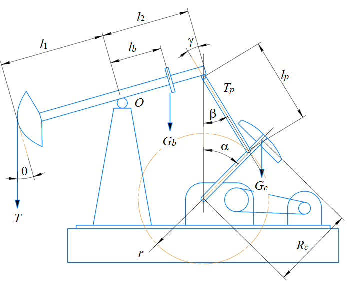
Pumping unit model. Kinematic and dynamic models (Fig.4) of the drive operation have been developed, taking into account the assumption that the joint point of the balance beam and the connecting rod moves along a trajectory close to a straight line, which is true for a small radius of the crank in comparison with the length of the rear arm of the balancer.
The kinematic relations have the form:
where \(\alpha\) – crank shaft angle; r – crank shaft radius; l1 – balance bar front arm length; l2 – balancer rear arm length; lp – connecting rod length (Fig.4).
The calculation of the stresses in the connecting rod is based on the equation of the moments of forces relative to the axis of the balance beam O rotation
where T – crank shaft angle; lb, Gb – respectively, the shoulder and weight of the balancing counterweight; Tp – force in the connecting rod of the crank shaft mechanism.
The torque on the crank shaft M is numerically equal to the product of the tangential force on the shoulder of its action:
where Rc, Gc – respectively, the radius and weight of the crank shaft counterweight.
Model for calculating the energy consumption of an electric motor. The useful mechanical power W, consumed by the electric motor is determined by the value of the torque on the shaft of the electric motor
where \(\omega\) – electric motor angle velocity; v1, v2 – gear ratios of the gearbox and V-belt transmission, determined by the ratio of the gearbox pulleys and the electric motor diameters.
During the operation of the SRPU, power losses occur in the elements of ground equipment, as a result of which the power consumption will always be more useful. The calculation of losses in the electric motor (EM) is complicated by the fact that the load, and hence the torque changes periodically in each swing cycle, respectively, all the EM parameters, including efficiency, change within each cycle. When the engine is operating with a periodically varying load, its efficiency and power factor depend on both the load factor KL, and the shape factor of the load curve KF. With a deterioration in balancing, KF increases, which leads to an additional decrease in motor efficiency.
By taking into account all the above the following methodology for calculating the power consumption of the SRPU for a pumping cycle is applied:
1. The efficiency of the electric motor is calculated, corresponding to the equivalent (rms value of power) according to the load factor of the electric motor,
where W,Wekv, Wr – instantaneous, equivalent and rated power of the electric motor, respectively, T – crank shaft rotation period.
2. The shape factor of the load curve is calculated
3. The cyclical value of the efficiency is calculated depending on the coefficient of the shape of the curve and the apparent power consumed by the installation,
where ηc – efficiency of the electric motor with a cyclic nature of the load; WΣ – rod power consumption.
Analysis of calculation results. The study of the influence loads on the drive formation influence and power consumption of the pumping unit is carried out for the pumping unit 7SK8-3.5-4000, which is widespread in mechanized oil production.
Technical parameters of the pumping unit 7SK8-3.5-4000: main balancing system – rotary; balance arm length: front l1 = 3500 mm, rear l2 = 2500 mm; connecting rod length lp = 3000 mm; the radius of rotation of the most distant point of the crank R = 1600 mm; the total mass of crank weights is 6080 kg.
Geological, technical and technological parameters of the well and the rod assembly: internal diameter of lift pipes – 62 mm; pump diameter – 57 mm; diameter of rods – 22 mm; the density of the material of the rods is 7800 kg/m3; pump lowering depth 1000 m; intake pressure 1-6 MPa; liquid viscosity 0.01 Pa∙s; liquid density 990 kg/m3; stroke length 2 m; number of swings 6 min-1.
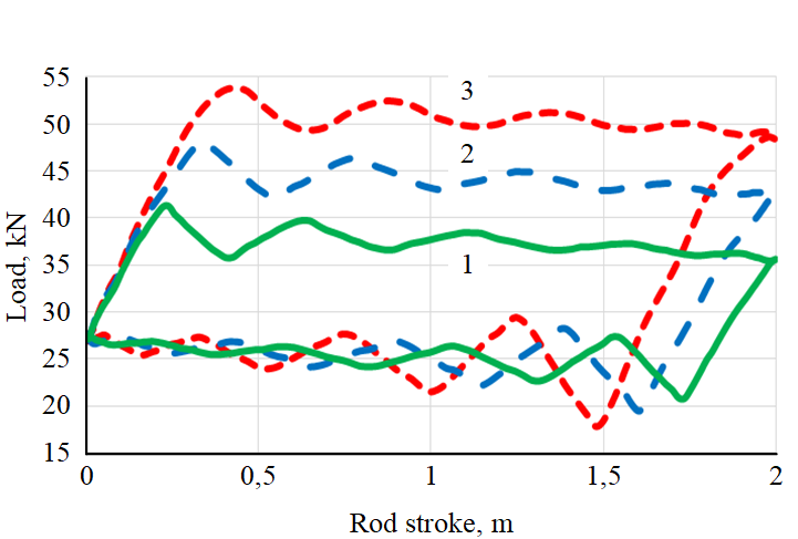
Figure 5 shows the dynamic loads on the balancer head at different values of the current dynamic level in the well. With an increase in the dynamic level, the pressure at the pump intake decreases and the differential pressure increases (the difference between the pressure at the discharge and the intake of the pump) and, accordingly, the liquid load on the pump plunger, which is reflected in a significant increase in loads in the half-cycle of the upward stroke of the rods (by about 40 % at the extreme positions of the dynamic level). In addition, with an increase in the dynamic level, the dynamic component of the load also increases, which leads to an increase in the maximum and decrease in the minimum loads on the balancer head.
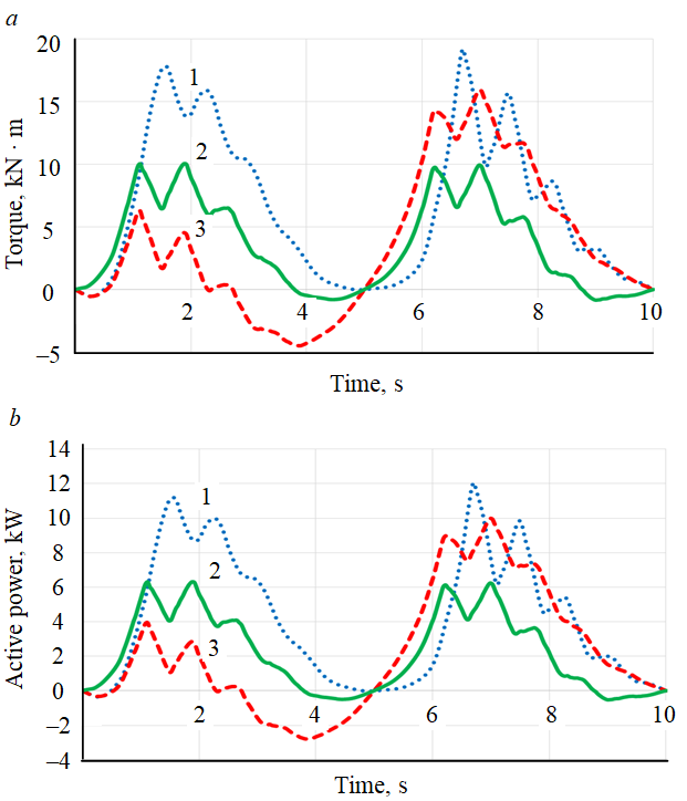
The change in the nature of the loads caused by fluctuations in the dynamic level has a significant effect on the amount of torque on the crank shaft. Balancing the PU only at a certain value of the dynamic level (for example, when the pumping mode is established, when the dynamic level is close to the lower limit) leads to a significant redistribution of torque in the process of changing the liquid level, and the degree of balance of the PU is significantly reduced: in the considered example, the ratio the amplitudes of the torque during the movement of the balancer head up and down for the upper position of the dynamic level increases to 3 (Fig.6, a). An automatic balancing system prevents such a development of events. When the dynamic level (DL) and the liquid load on the plunger change, it adjusts the position of the balancing weights to ensure the balance of the PU. As a result, the automatic balancing system allows almost 1.5 times (50 %) to reduce the maximum torque on the crank shaft, which means to ensure a more even loading of the electric motor and drive belts.
The active power consumed by the electric motor is proportional to the torque (Fig.6, b). Due to the equalization of the torque and the load on the electric motor, the automatic balancing system can significantly reduce the maximum (instantaneous) power consumed by the electric motor (from 10 to 6 kW). In addition, the automatic balancing system makes it possible to exclude the operation of the electric motor in the generator mode (characterized by negative active power with an amplitude of up to –3 kW) at the end of the first half-cycle of pumping, which has a negative effect on the operation of the electric motor and the network.
The results of calculating the electricity consumed by the sucker rod are presented in the table. Since an increase in the dynamic level reduces the work required to lift the pumped product, the power consumed by the sucker rod unit is reduced by 1.5 times (from 8.7 to 5.7 kW). Due to the equalization of the torque and load on the electric motor, the SRPU with an automatic balancing system is characterized by a lower value of the form factor of the EM load curve (1.33 versus 1.36 for the SRPU without an automatic balancing system). As a result, the power consumed by the sucker rod unit is also reduced by 9 % (from 6.2 to 5.7 kW).
Energy indicators SRPU
| Index | Equivalent power, kW | Form factor | Cyclic load efficiency | Power consumption, kW |
| DL lower limit | 5,5 | 1,34 | 0,63 | 8,7 |
| DL upper limit (SRPU with automatic balancing system) | 3,1 | 1,33 | 0,62 | 6,2 |
| DL upper limit (USSHN without automatic balancing system) | 4,1 | 1,36 | 0,64 | 5,7 |
Conclusion
1. It is shown that during the operation of wells with sucker rod units operating in the periodic pumping mode, significant fluctuations in the dynamic level occur, which leads to a significant change in the nature of the loads acting on the plunger and the drive, and a decrease in the degree of balance of the drive. The need to develop mechanisms and systems for automatic balancing of the balance drive (of pumping units) has been substantiated.
2. A system for automatic balancing of the balancer drive of the rod unit has been developed. To study the effectiveness of the proposed device, a complex mathematical model of the joint operation of the reservoir – well – sucker rod pump – rod string – drive system has been developed. In contrast to the existing ones, the proposed complex model takes into account the effect of fluctuations in the dynamic fluid level on the value of dynamic loads acting both on the downhole equipment (plunger, rod string) and on the units of the pumping unit (balance beam, crank mechanism, gearbox). In addition, the proposed model takes into account the influence of dynamic level fluctuations on the degree of balance of the pumping unit and the power consumption of the sucker rod pumping unit.
3. It is shown that by adjusting the position of the balancing counterweight and ensuring constant balancing of the PU, the automatic balancing system makes it possible to reduce the maximum torque on the crank shaft by almost 1.5 times (by 50 %) (in comparison with a sucker rod unit without an automatic balancing system), which means to ensure a more uniform loading of electric motors and drive belts.
4. It is shown that due to the equalization of the torque and the load on the electric motor, the rod unit with an automatic balancing system is characterized by a lower value of the shape factor of the ED loading curve (1.33 versus 1.36 (by 5 %) for the SRPU without automatic balancing system). As a result, the power consumed by the rod installation also decreases (by 9 % in the design example).
5. The results obtained confirm the effectiveness of the equipment of pumping units with an automatic balancing system, especially when operating wells in a periodic pumping mode.
References
- Antonychev S.V. Dynamic balancing of pumping units in terms of power consumption using the Balance SK-2 device. Tekhnologii nefti i gaza. 2013. N 3, p. 50-53 (in Russian).
- Gilaev G.G., Bakhtizin R.N., Urazakov K.R. Modern methods of pumping oil production. Ufa: Vostochnaya pechat, 2016, p. 410 (in Russian).
- Bakhtizin R.N., Urazakov K.R., Ismagilov S.F., Topolnikov A.S., Davletshin F.F. Dynamic Model of a Rod Pump Installation for Inclined Wells. SOCAR Proceedings. 2017. N 4, p. 74-82. DOI: 10.5510/OGP20170400333
- Urazakov K.R., Nurgaliev R.Z., Bikbulatova G.I., Sabanov S.L., Boltneva Yu.A. Research of Loads on Drive of Rod Installations in Low Speed Mode at High-Viscous Oil Production. Oil and Gas Business. 2020. Vol. 18. N 1, p. 120-129. DOI: 10.17122/ngdelo-2020-1-120-129 (in Russian).
- Galeev A.S., Nurgaliev R.Z., Bikbulatova G.I., Sabanov S.L., Boltneva Ju.A. Criterion of Low-Speed Well Rod Pumping Drive Unit Balancing for Gearbox’s Reliability Increasing. Oil and Gas Business. 2019. Vol. 17. N 6, p. 96-101. DOI: 10.17122/ngdelo-2019-6-96-101 (in Russian).
- Urazakov K.R., Tugunov P.M., Shaizhanov N.S., Ishmukhametov B.Kh., Ismagilov S.F. Patent №. 2626616 RF. Device for measuring the number of oscillations of the pumping unit. Publ. 31.07.2017. Bul. N 22 (in Russian).
- Urazakov K.R., Bakhtizin R.N., Usmanov R.V., Tugunov P.M., Gorshunova L.P. Patent №. 2682231 RF. Installation for testing sucker rod pumps. Publ. 15.03.2019. Bul. N 8 (in Russian).
- Urazakov K.R., Molchanova V.A., Tugunov P.M., Baryshnikov Yu.N., Alimetov Sh.A. Patent №. 2709589 RF. Pumping unit. Publ. 10.10.2019. Bul. N 28 (in Russian).
- Tagirova K.F., Vulfin A.M., Ramazanov A.R., Fatkhulov A.A. Improving the Efficiency of Operation of Sucker-Rod Pumping Unit. Oil Industry. 2017. N 7, p. 82-85. DOI: 10.24887/0028-2448-2017-7-82-85 (in Russian).
- Sofina N.N., Shishlyannikov D.I., Kornilov K.A., Vagin E.O. Method of Control Parameters and Technical Condition of the Downhole Sucker Rod Pumping Units. Master’s Journal. 2016. N 1, p. 247-257 (in Russian).
- Khakimyanov M.I., Khusainov F.F., Shafikov I.N. Problems of Improving the Energy Characteristics of Downhole Sucker Rod Pump Electric Drives. Electrotechnical Systems and Complexes. 2017. N 2 (35), p. 35-40. DOI: 10.18503/2311-8318 (in Russian).
- Khakimyanov M.I. Energy Intensity in Artificial Lift of Sucker Rod Pumping Units. Vestnik Ufimskogo gosudarstvennogo aviatsionnogo tekhnicheskogo universiteta. 2014. Vol. 18. N 2(63), p. 54-60 (in Russian).
- Shipulin A.V., Kupavykh K.S., Kupavykh A.S. Increasing the energy efficiency of the pumping unit during the formation of pulsed hydraulic fracturing cracks. Nauchno-tekhnicheskie vedomosti Sankt-Peterburgskogo politekhnicheskogo universiteta Petra Velikogo. 2016. N 4 (254), p. 39-44. DOI: 10.5862/JEST.254.5 (in Russian).
- Shishlyannikov D.I., Rybin A.A. Assessment of load of beam-balanced pumping units by electric motor power indicators. Journal of Mining Institute. 2017. Vol 227, p. 582-588. DOI: 10.25515/PMI.2017.5.582
- Guluyev G., Pashayev A., Pashayev F., Rzayev A., Sabziyev E. Building the dynamometer card of sucker rod pump using power consumption of the electric motor of pumping unit. IV International Conference “Problems of Cybernetics and Informatics”, 12-14 September 2012, Baku, Azerbaijan, IEEE, 2012, p.1-3. DOI: 10.1109/ICPCI.2012.6486365
- Dvoynikov M., Kunshin A., Blinov P., Morozov V. Development of mathematical model for controlling drilling parameters with screw downhole motor. International Journal of Engineering. TransactionsA: Basics. 2020. Vol. 33. N 7, p. 1423-1430. DOI:10.5829/ije.2020.33.07a.30
- Gabor T. Sucker-rod pumping handbook: production engineering fundamentals and long-stroke rod pumping. Houston, Texas: Gulf Professional Publishing, 2015, p. 598.
- Lavrenko S.A., Klushnik I.D., Iarmolenko V.A. Test results for hydraulic drives of sucker-rod pumping units. ARPN Journal of Engineering and Applied Sciences. 2019. Vol. 14. N 16, p. 2881-2885.
- Mardashov D.V., Vasiliev B.U. Methodology of educational process organization using training simulator. IEEE Conference on Quality Management, Transport and Information Security, Information Technologies (IT and MQ and IS), 4-11 October, 2016, Nalchik, Russia, p. 5. DOI: 10.1109/ITMQIS.2016.7751924
- Hansen В., Tolbert B., Vernon C., Hedengren J.D. Model predictive automatic control of sucker rod pump system with simulation case study. Computers and Chemical Engineering. 2019. Vol. 121, p. 265-284. DOI: 10.1016/j.compchemeng.2018.08.018
- Zheng B., Gao X., Li X. Fault detection for sucker rod pump based on motor power. Control Engineering Practice. 2019. Vol. 86, p. 37-47. DOI: 10.1016/j.conengprac.2019.02.001Get