
Analysis of technological schemes for creating a geodetic control at the industrial site
- 1 — Ph.D., Dr.Sci. Professor Siberian State University of Geosystems and Technologies ▪ Orcid
- 2 — Ph.D. Associate Professor Siberian State University of Geosystems and Technologies ▪ Orcid
- 3 — Ph.D. Associate Professor Siberian State University of Geosystems and Technologies ▪ Orcid
- 4 — Ph.D. Head of the Department Siberian State University of Geosystems and Technologies ▪ Orcid
- 5 — Ph.D. Associate Professor Siberian State University of Geosystems and Technologies ▪ Orcid

Abstract
The article highlights the issues of creating with the necessary accuracy a planned control on the industrial site of the engineering structures under construction using satellite technologies and total stations. Depending on the design features of the engineering structures under construction, as well as the technological scheme for the installation of building constructions and industrial equipment, various schemes for creating such control are considered, based on the application of the inverse linear-angular notch. Errors in the source data are one of the main errors that affect the accuracy of geodetic constructions, including the solution of the inverse linear-angular notch. When creating a geodetic network in several stages, the errors of the initial data of the first stage affect the values of the root-mean-square errors (RMS) of determining the position of the second stage points, the errors of which affect the value of the RMS of the position of the third stage points, etc. The reason for their occurrence is the errors of geodetic measurements that occur at each stage of control creating, as well as the stability violation of the points during the production of excavation, construction and installation works. When determining the coordinates of a separate project point at the stage of its removal in-situ by a total station, the entire network is not equalized in the vast majority of cases, and the coordinates of the starting points to which the total station is oriented are considered error-free. As a result, the RMS determination of the points coordinates of the control network or the removal of the design points of the elements of building structures and equipment will also be considered satisfying the requirements, i.e. the measurement accuracy will be artificially overestimated and will not correspond to the actual one obtained. This is due to the fact that the accumulation of errors in the initial data is not taken into account when the number of steps (stages) of control creating increases. The purpose of this work is to analyze the influence of measurement errors and initial data when creating a geodetic control on an industrial site by several stages of its construction based on inverse linear-angular notches and a priori estimation of the accuracy of the determined points position.
None
Introduction
For the construction of engineering structures and installation of technological equipment on industrial sites, a planned high-rise control is being created, consisting of the following parts (SP 126.13330.2017 “Geodetic works in construction”, SP 47.13330.2012 “Engineering surveys for construction”, SP 70.13330.2012 “Load-bearing and enclosing structures”):
- external center control designed to ensure the design relative location of buildings and structures, stakeout of the main axes of objects under construction, engineering support networks, the production of executive surveys and geodetic deformation monitoring;
- internal center network of the building (structure) on the initial and installation horizons for the construction of these buildings and structures, as well as the enlarged installation of technological equipment.
Also, for step-by-step installation of technological equipment, local center networks are additionally created, taking into account the design of this equipment.
The specified geodetic networks are created with an accuracy that meets the requirements of regulatory documents (SP 126.13330.2017, 47.13330.2012, 70.13330.2012), as well as documents for the installation of the technological equipment used, for example, turbine units, reactors, steam generators, etc. In some cases, the accuracy of creating networks is specified in the developed project for the production of geodetic works, while it increases at each subsequent stage of their creation (internal control).
Previously, the external control creation was made in the form of a construction grid, which had the sides of square or rectangle with a length of mostly 100 or 200 m [16]. After all geodetic measurements, their processing and evaluation of the accuracy of determining coordinates for all points of the construction grid as a whole were performed, which were then assumed to be equivalent, and relative to them, center work was carried out in the future – the stakeout of the main and general axes of engineering structures and often technological axes of equipment.
And currently, in some cases, design organizations recommend creating an external control in the form of a construction grid with any length of the sides of a square or rectangle. However, when performing geodetic measurements at the points of the created grid, it is prescribed to use satellite technologies or linear-angular constructions using high-precision total stations.
With the advent of satellite technologies and total stations in geodetic production, the technological scheme for creating an external control, the method of performing measurements has changed significantly, as well as obtaining coordinates at the industrial site with the required RMS value has been significantly simplified, and the time required for performing measurements has also been reduced.
Due to the fact that the creation of an external center control in the form of a construction grid at the industrial site has largely stopped, it was replaced by satellite measurement technologies, as well as ground-based methods – the method of a free station or polar coordinates (polar notch). However, the practice of their application shows that in some cases the calculation of the coordinates of the control points occurs without preliminary joint equalization of the measurement results. This circumstance is aggravated by further condensing of the external control of the industrial site, since the errors of the initial data of the previous stage points of the control are not taken into account, which leads to the accumulation of errors when determining the coordinates of each subsequent stage points. Because of this, unacceptable distortions arise in the linear-angular constructions of all stages of the planned high-altitude control of the industrial site, which significantly reduces the accuracy of the center work. This factor is especially true when determining the coordinates of the control points by solving the inverse linear-angular notch or the method of polar coordinates. Therefore, the article considers the schemes for creating the initial planning control of an industrial site, as well as various schemes for the development of its condensing stages, based on the application of the method of inverse linear-angular notch and polar coordinates. The analysis of the errors influence in the initial data of the previous stage of control on the RMS value of determining the coordinates of the subsequent created stage, including the final RMS value of the stakeout (or determination) of the main and general axes of structures, center points for the installation of individual building structures during the construction of engineering works, the preliminary location of center axes for the technological equipment installation.
Measurement methods
Let us consider technological schemes for creating a planning control on the example of industrial sites of responsible engineering structures – nuclear or thermal power plants.
Depending on the number of projected blocks, the industrial sites of nuclear or thermal power plants have an area of 2-4 km2. This circumstance requires the creation of a center network over a large area, with the required value of the mutual position of points, which in some cases is provided by the use of satellite technologies (SP 126.13330.2017) [8, 18]. The creation of a planned high-altitude control on such industrial sites is carried out mainly in the following sequence:
- transfer of coordinates to three or four points of planning and high-altitude control to the territory of the industrial site from the points of the state geodetic network or a network of permanent base stations in order to establish a connection between the state (or regional) and conditional coordinate systems of the construction site;
- creation of a planned high-altitude control of an industrial site with satellite technologies or linear-angular constructions. In order to avoid the influence of errors in the initial data and the transmission of coordinates to the industrial site, the network is equalized as free;
- for the convenience of performing detailed center work in the conditions of the construction site, the planned high-altitude control is condensed by creating several stages;
- performing center work on an industrial site for the installation of building structures;
- creation of an internal center network of the structure and transfer of coordinates to the installation horizons for its construction and production of executive surveys [5, 6, 17];
- creation of a detailed (local) planned high-altitude control of higher accuracy with an increase in the number of points for the installation of technological equipment.
The method of creating detailed center constructions for the installation of technological equipment is not considered in the article.
Figure 1 shows the location of the main engineering structures of the NPP: reactor blocks, turbine halls and cooling towers.
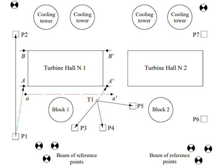
Fig.1. Location diagram of the main buildings at the NPP industrial site
To create an external center control, the planned coordinates were transmitted by satellite technologies from a point of the state geodetic network or a base station to a part of the control points of the industrial site, for example, to points P1, P2, P3, P4 and P5. According to the requirements of the regulatory document SP 126.13330.2017, the RMS of relative determination of the centers position of the control points relative to the point of the state geodetic network or the base station should not exceed the value of 5 mm + 0.5 mm/km, and the limit error value in the post-processing mode is 20.0 mm. This means that the error value of the relative position of two adjacent network points can be 25-30 mm. Table 5.1 of the regulatory document SP 126.13330.2017 indicates that the limit error value of the relative position of the external center control points can reach 50.0 mm. At the same time, paragraph 6.1 specifies that the internal center network should be created on the initial horizon from the external center control points. In this regard, the removal of the main and general axes of engineering structures, especially responsible ones, from adjacent (different) points of external control, taking into account these errors of their relative location, will be made with gross errors [13]. Therefore, in order to exclude the influence of unacceptable errors in the position of the external control points on the position of the internal network points, according to paragraph 6.3 of the specified normative document, it is prescribed to create an internal center network, and for the working (initial) coordinate system of this network to take the intersection point of the digital and letter axes of the structure on the initial horizon (the finished floor level). This requirement is consistent with the previously stated position of the author of the work [7], which considers two types of engineering and geodetic measurements accuracy performed on an industrial site: the accuracy of the entire engineering structure placement (its main axes) relative to the surrounding objects on the industrial site (the first type); the accuracy of the individual parts partition of this structure relative to its main axes (the second type).
In this case, it is permissible to shift or turn the entire building from its design position by 5-10 cm (the first type of accuracy), but it is unacceptable to ensure the required accuracy of the relative position of its main axes (the second type of accuracy).
This approach was used several decades ago, when geodetic instruments could provide RMS of the relative position of adjacent control points only of the order of 10-30 mm at the above-mentioned dimensions of the industrial site. Therefore, these control points could not be the starting points for the removal of the main and general axes of the structure for the installation of building structures, for example, columns, since they did not meet the requirements of the regulatory document SP 70.13330.2012 to ensure the RMS values of the planned displacements of the axes of columns and supports relative to the center axes when they are installed on the foundation (they should not exceed 5.0 mm).
Obtaining the third coordinate for creating an external control and an internal network was carried out by transferring the heights to the industrial site (to the beams of deep reference points and external control points) by high-precision geometric leveling according to the class II program (depending on the responsibility of the structures) from the nearest reference points of the state leveling network of class II, rarely – I. Further development of the leveling network when creating an external control, as well as an internal network, was carried out by leveling class III.
For the technological equipment installation inside these structures, a detailed (local) planning and high-altitude control was created – engineering and geodetic networks with the accuracy specified in the technical documentation for the installation and operation of specific equipment. To create such networks, special measurement methods were used: string-optical, direct optical sight, moving mark, coordinate, leveling with short rays, etc. At the same time, the connection of the external planned high-altitude control, internal high-precision engineering and geodetic and local networks was carried out only for the purpose of general linking of the design (or actual) coordinates of the building structures of engineering works located on the industrial site and the used equipment.
With the appearance of high-precision geodetic measuring instruments, which began to provide RMS for determining the coordinates of external control points of the order of 2.0-5.0 mm, new methods and schemes for creating engineering and geodetic networks using satellite technologies or linear-angular constructions with a total station [1, 3, 15] were developed, and the procedure for carrying out center work was improved. This is especially true for engineering and geodetic measurements performed by a total station [4, 11, 12]. For example, the center elements of the removed points of the axes of the structure are calculated by the total station processor directly on the industrial site, at the place where the corresponding measurements are performed [2, 3]. With this in mind, the ratio of the accuracy parameters for determining the coordinates of the external control points of the industrial site and the internal center network points of the engineering structure has changed significantly. Under favorable external conditions (cloudy weather, small distances up to 30-50 m), it became possible to perform measurements using a high-precision total station, create an internal center network directly from the external control points of the industrial site. This significantly blurs the line between the RMS of determining the coordinates of the external control points of the industrial site and the internal center network points. This statement will be valid if, when creating an external control and an internal center network, one of the main errors of engineering and geodetic measurements is taken into account – the errors of the initial data [9, 10]. However, when performing measurements for the purpose of creating or further condensing engineering and geodetic constructions on the industrial site, very often the performers do not consider the error values of the initial data of the previous stage of control condensing, i.e. the RMS of determining its coordinates is assumed to be zero [20]. This leads to an artificial overestimation of the accuracy of determining the coordinates of the total station location when solving the inverse linear-angular notch, which is calculated by the total station software, as well as the center points of the axes of the engineering structure.
When engineering and geodetic constructions are condensed by several stages, there is a sequential accumulation of the influence of errors in the initial data of each stage, which ultimately affects the RMS value of determining the position of the removed points.
Using the example of creating an external justification for the NPP industrial site, we will consider the mechanism of accumulation and the amount of influence of errors in the initial data of several stages of condensation on the accuracy of the center work.
Using satellite technologies at the industrial site (Fig.1), the planned coordinates of points P1, P2, P3, ..., Pn with RMS, recommended by the regulatory document SP 70.13330.2012 [16], were determined. It is also required to bring the AB axis of the turbine hall in-situ. The removal of the beginning of this axis (point A) is possible from point P1 by the method of polar coordinates, and the end of the axis (point B) from point T1, which coordinates were determined by the solution of the inverse linear-angular notch. Taking into account the above values of the RMS of the relative position of points P1, P2, P3, P4 and P5, the removal of the beginning and end of the AB axis will be carried out with an error of the order of 20.0-30.0 mm. With the same error, other axes of the turbine hall will be taken out, for example, the CD axis. As a result, the RMS of the relative position of the axes will not meet the requirements of Table.7.1 of the regulatory document SP 126.13330.2017, which states that this value should not exceed 5.0 mm.
Thus, the main weak point on the industrial site in the chain “external control-internal network” is the creation of an external control with RMS, which provides the possibility of carrying out the main and general axes of structures from any points of this external control. Such control should provide an RMS of the relative location of network points of no more than 2.0-3.0 mm. To solve this problem, an external control must be created in three stages.
- Determination of the planned high-altitude coordinates of points P1, P2, P3, ..., Pn relative to points of state networks or base stations with satellite technologies with the accuracy recommended by the regulatory document SP 126.13330.2017. These points are a pile or tubular structure [15], often with forced centering.
- Redefining the planned coordinates of points P1, P2, P3, ..., Pn in the relative coordinate system (in the coordinate system of the industrial site) by the following linear-angular constructions: by the method of polygonometry; by the solution of the inverse linear-angular notch; by the method of polar coordinates. The measurements should be carried out with high-precision total stations that provide RMS measurements of distances of 1.5-2.0 mm and angles of 1.0-2.0", in order to determine the coordinates of the control points after equalization with RMS of the order of 2.0-2.5 mm.
- Further condensing of the external control by high-precision total stations by solving the inverse linear-angular notch or by the method of polar coordinates.
At the first stage of creating an external control the determination of the planned high-altitude coordinates of points P1, P2, P3, ..., Pn relative to points of state networks or base stations with satellite technologies does not provide the required accuracy of the removal of the main axes of the structure. Therefore, at the second stage, it is necessary to redefine the coordinates of the external control points with their equalization and accuracy assessment, as well as with the setting of a conditional coordinate system, after which the external control will satisfy the required accuracy and be the first stage. From these points, it is possible to carry out the removal of the axes of structures in-situ. Therefore, with the P1 method of polar coordinates, it is possible to carry out the removal of the point A of the AB axis of the turbine hall. Then, using points P3, P4 and P5 of the control by solving the inverse linear-angular notch, the coordinates of the point T1 of the total station are determined. After that, it is possible to carry out the removal of the point B of the AB axis, which is also performed by the method of polar coordinates using the initial orientation of the total station telescope to any of the three points P3, P4 or P5 of the control.
An important feature of determining the coordinates of the point T1 of the total station is the fact that these coordinates are the second stage of external justification, and the RMS value of their obtaining should not exceed 2.5-3.0 mm. This is due to the fact that according to the requirements of Table 7.1 of the normative document SP 126.13330.2017, the value of the maximum error of the relative position of the overall axes set out in the plan should not exceed 5.0 mm. This means that, taking into account the requirement for high accuracy of the relative position of the removed axes of the structure, it is necessary to carefully perform geodetic measurements, as well as fix the removed points, in our case, points A and B (Fig.1). Currently, they are fixed by notching on a metal surface with subsequent painting or installation (gluing) of retroreflective films on building structures.
The need for careful fixing of the points of the removed axes is also due to the fact that in the vast majority of cases they are used for further condensing the external planned high-altitude network at the industrial site and will be the third stage of external control. They will also be used to create an internal control of engineering structures.
Thus, the creation of a control on the industrial site occurs through the consistent development of local stages. At the same time, the subsequent local control stage is based on the previous one, the coordinates of which are taken as the initial and error-free source data, i.e. the coordinates of the initial data when they are entered into the total station are assumed to be error-free and do not affect the accuracy of obtaining the coordinates of the subsequent stage. However, errors in the coordinates of each stage always affect the RMS value of obtaining the coordinates of the next stage, and this influence accumulates with an increase in the number of stages. As a result, the obtained RMS values for determining the coordinates of the total station standing points (errors in the initial data are not taken into account), in our case, points T1 and T2 of the second stage, will differ from the actual values (under the influence of errors in the initial data).
Taking into account the above, we will analyze the influence of errors in the initial data of the previous stage of control on the results of the RMS position of the next stage points using various measurement schemes. When implementing the measurement method, two or three initial points of control will be used, as the most commonly used schemes in production.
Scheme N 1
Let's consider a scheme on an industrial site with an area of 2-4 km2 (on a scale of 1:3500), in which, as a result of redefining the planned coordinates of the starting points P3, P4 and P5 (Fig.2, the dimensions are indicated in meters), their new coordinates with an RMS of 3.0 mm are obtained.
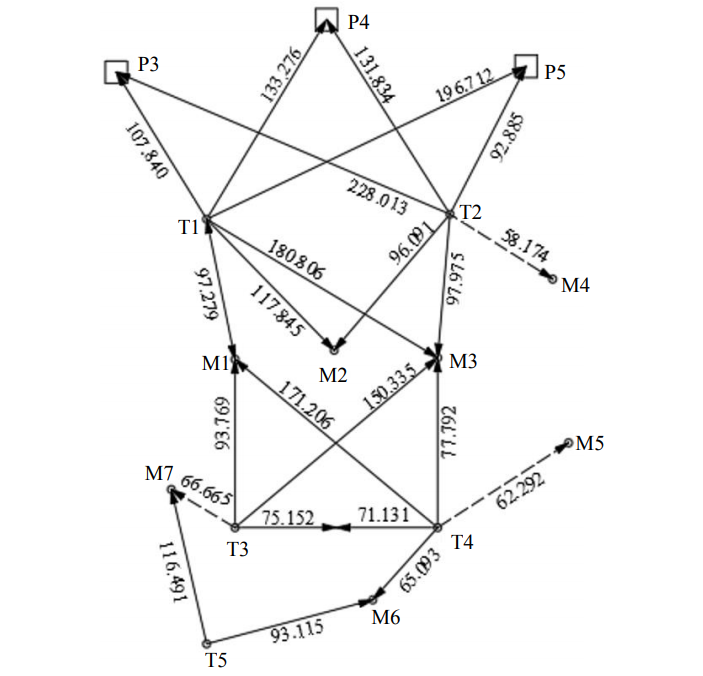
Fig.2. Scheme N 1 of the condensation of the external control
Let's assume that the position of the projected points T1 and T2 (standing of the total station of the second stage) will be determined by the solution of the inverse linear-angular notch, the center points M1, M2, M3 and M4 by the method of polar coordinates, the points T3, T4 and T5 (standing points of the total station) also by the solution of the inverse linear-angular notch and, finally, the center points M5, M6 and M7 again by the method of polar coordinates. To control the removal of points M1, M2 and M3, polar notch measurements can be performed (if there is visibility) from points T1 and T2. Let's also assume that the measurements of angles and line lengths are made with errors, respectively mβ = 2.0" and mS = 2.0 mm.
The points T1, T2, T3, T4 and T5 of the total station can be fixed in the following ways: with the center of the treger on a tripod; with wooden stakes with small nails driven into the end; with a notch or notching on a metal or concrete surface.
Fixing the specified points of the total stations standing with the help of a tribrach (the axis of total stations rotation) on a tripod is temporary. If a tripod with a total station is installed on an unstable base (weak ground, snow cover, asphalt, vibration of the tripod due to the work of construction equipment, etc.), then over time, for example, after 30-50 min, it is necessary to redefine the coordinates. It should be noted that at the construction stage, the main influence on the tripod stability is provided by the developed ground of the pits and snow cover. The practice of performing work on the industrial site shows that in the case of the influence of these factors, the change in the coordinates of the total station can reach 2.0-3.0 mm. If it is necessary to fix the total station standing points for a long time, it is necessary to use the second or third methods, because of which an additional error for centering the total station equal to 1.0-1.5 mm appears.
Let's consider the nature and magnitude of the accumulation of the errors influence in the initial data on the RMS of determining the coordinates of the control points created according to scheme N 1, sequentially, as the number of stages of its condensation gradually increases.
Using points P3, P4 and P5 of the first stage of the external control, it is required to perform its condensation by the second stage, i.e. to determine the coordinates of points T1 and T2 of the total station with an inverse linear-angular notch, and then the center points M1, M2, M3 and M4 by the method of polar coordinates. The position of these center points will be “hanging” and to exclude this fact, the control determination of their coordinates can be performed several times by independent measurements by aiming to other starting points of the first stage.
In this case, also taking the error values of the initial data equal to 3.0 mm, mS = 2.0 mm and mβ = 2.0", and the values of the measured elements of the linear-angular network given in Table 1, we obtain the RMS values for determining the position of the points T1 and T2 of the total station of the second stage and the center points M1, M2, M3 and M4 (Table 1). As a rule, the fixing of the obtained center points is made by retroreflective films or by notching on concrete or steel surfaces of building structures with their subsequent painting.
Table 1
RMS positions of points T1 and T2 of the second stage of the network N 1 and center points (taking into account the errors of the initial points P3, P4 and P5 of the first stage)
|
Point |
M, mm |
Mx, mm |
My, mm |
|
Т1 |
3.3 |
2.2 |
2.4 |
|
Т2 |
3.5 |
2.4 |
2.6 |
|
М1 |
6.4 |
4.3 |
4.8 |
|
М2 |
4.8 |
2.9 |
3.8 |
|
М3 |
6.7 |
4.5 |
5.0 |
|
М4 |
6.4 |
4.4 |
4.6 |
The obtained RMS values of the positions of points T1 and T2 were 3.3 and 3.5 mm, respectively, and the center points M1, M2, M3 and M4 were from 4.8 to 6.7 mm. This accuracy is sufficient to connect the coordinates of the external control with the coordinates of the internal center network, as well as to perform center work for the installation of columns, glass-type foundations, formwork for concrete work, installation of underground utilities.
Suppose that it is necessary to perform a further condensation of the control by the third step. To do this, you can use the center points M1, M2 and M3, which they were when implementing the second stage of condensing. When performing further condensing, the obtained coordinates of the points M1, M2 and M3 with the specified RMS value can be the third stage of control and used as starting points for further condensing the control.
For further condensing (obtaining the fourth stage) , when installing the total station at points T3 and T4, we use the points M1 and M3 of the third stage as the starting points and apply the inverse linear-angular notch. The data from Table 1 will be taken as the error values of the initial data of points M1 and M3. To control the obtained coordinates of the fourth stage, it is possible to additionally perform measurements with relative sighting between points T3 and T4 (Table 2).
Such a value of RMS for determining the position of the starting points T3 and T4 and the center points M5, M6 and M7 is not sufficient to connect the coordinates of the external control with the coordinates of the internal center network and center work for the columns installation, but it will be sufficient for the center work of individual structural elements of the construction, for example, when installing glass-type foundations, formwork for concrete work, installation of underground utilities, etc.
Table 2
RMS positions of points T3 and T4 of the fourth stage of the network N 1 and center points (taking into account the errors of the initial points M1 and M3 of the third stage)
|
Point |
M, mm |
Mx, mm |
My, mm |
|
Т3 |
9.9 |
6.5 |
7.5 |
|
Т4 |
10.3 |
7.2 |
7.3 |
|
М5 |
13.5 |
11.0 |
7.8 |
|
М6 |
13.6 |
7.8 |
11.1 |
|
М7 |
14.0 |
11.3 |
8.3 |
If we continue to condense the control, for example, determining the coordinates of point T5 (fifth stage), then the RMS of the obtained coordinates, with the above accuracy of measurements, will be equal to Mx = 10.2 mm, My = 13.2 mm and M = 16.7 mm, which will meet the requirements only when performing executive surveys of underground and aboveground communications, as well as obtaining topographic plans of the industrial site at a scale of 1:500.
Thus, the total error of the point position T5, due to the influence of random measurement errors and the initial center points M6 and M7 at the fifth stage of condensation, is M ≈ 17.0 mm.
The condensation of the external control for the purposes of carrying out center work for construction and installation works using this measurement scheme is possible only up to the fourth stage, taking into account the influence of errors in the initial data.
Scheme N 2
In the production of geodetic works on industrial sites of elongated shape, a scheme for creating a control in the form of a “stroke” of consecutive inverse linear-angular notches is often used (Fig.3). In contrast to the classic total station stroke, the orientation of the total station is performed not by one (rear) point of this stroke, but by three at once. In this case, first, the points P1, P2 and P3 of the external control (the first stage) act as the starting points, the position of which is estimated by an error of about 2.0-3.0 mm, and then, after determining the coordinates of the point T1 of the total station (the second stage) from the solution of the inverse linear-angular notch and its subsequent orientation to one of the starting points of the first stage, for example, point P1, the center points M1, M2, M3 (the third stage) are taken out by the polar method, which will be the starting points for the fourth stage of the control. Due to the fact that the points M1, M2, M3 are “hanging”, it is advisable to perform measurements with at least two techniques at two positions of the circle to increase the accuracy of their determination [19].
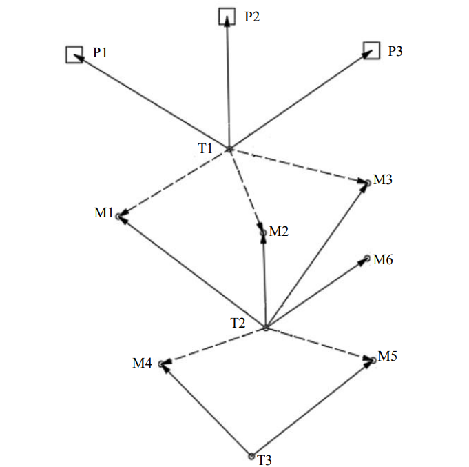
Fig.3. Scheme N 2 of the condensation of the external control
Let us consider the accumulation of errors in the position of the points of scheme N 2 (on a scale of 1:3500) when it is sequentially condensed by steps by solving inverse linear-angular notches and the method of polar coordinates.
The coordinates of the point T1 of the second stage are determined by the solution of the inverse linear-angular notch using points P1, P2 and P3 of the first stage, and the coordinates of the center points M1, M2 and M3 (the third stage) are determined by the polar method. The results of evaluating the accuracy of their position are shown in Table 3.
The coordinates of the point T2 of the fourth stage are determined by the solution of the inverse linear-angular notch using the points M1, M2 and M3 of the third stage, and the coordinates of the center points M4, M5 and M6 (fifth stage) are determined by the polar method. The results of evaluating the accuracy of their position are shown in Table 4.
Table 3
RMS of the position of point T1 of the second stage of the network N 2 and the center points M1, M2 and M3 (third stage), taking into account the errors of the initial data of points P1, P2 and P3 of the first stage
|
Point |
M, mm |
Mx, mm |
My, mm |
|
Т1 |
3.4 |
1.9 |
2.8 |
|
М1 |
6.5 |
4.1 |
5.0 |
|
М2 |
6.6 |
4.2 |
5.1 |
|
М3 |
6.7 |
4.4 |
5.1 |
Table 4
RMS of the position of the point T2 of the fourth stage and the center points M4, M5 and M6 (fifth stage), taking into account the errors of the initial data of the points M1, M2 and M3 of the third stage
|
Point |
M, mm |
Mx, mm |
My, mm |
|
Т2 |
7.8 |
4.2 |
6.6 |
|
М4 |
13.7 |
8.7 |
10.5 |
|
М5 |
14.3 |
9.6 |
10.6 |
|
М6 |
13.1 |
9.5 |
9.0 |
If, due to production necessity, further condensing of the control is required, for example, determining the coordinates of point T3 (sixth stage) with the above measurement accuracy, then the RMS of the obtained coordinates will reach the values M = 14.7 mm, Mx = 9.4 mm and My = 11.3 mm. Such RMS values will meet the requirements only when splitting individual structural elements of the construction, for example, the installation of glass-type foundations, formwork for concrete work, installation of underground utilities, etc.
It is necessary to perform a mathematical processing of the scheme N 2 of the condensation of the external control (Fig.3) using a synthesized (LS-optimization) algorithm [14] with the following conditions for evaluating accuracy:
- without taking into account the influence of errors in the initial data of points P1, P2 and P3 (the influence of only random measurement errors mβ = 2.0"and mS = 2.0 mm is taken into account);
- taking into account the combined influence of errors in the initial data of points P1, P2 and P3 (the error in the position of each point is mi.d.= 3.0 mm) and random measurement errors (mβ = 2.0" and mS = 2.0 mm).
The results of the accuracy assessment for the combined equalization of scheme N 2 are shown in Table 5, from which it follows that, taking into account the influence of errors of the starting points P1, P2 and P3, the RMS values of the positions of the determined points in the network will be approximately twice as large as without taking them into account and for the final point T3 M = 11.5 mm.
Table 5
Statement of accuracy assessment of the points position of the network N 2 based on the results of its combined equalization
|
Point |
Evaluation taking into account the influence of only random measurement errors (mβ = 2.0" andmS = 2.0 mm) |
Evaluation taking into account the influence of random measurement errors (mβ = 2.0" andmS = 2.0 mm) and the initial data (mi.d = 3.0 mm) |
||||
|
M, mm |
Mx, mm |
My, mm |
M, mm |
Mx, mm |
My, mm |
|
|
|
|
|
|
|
|
|
|
Т1 |
1.2 |
0.5 |
1.1 |
3.4 |
1.9 |
2.8 |
|
М1 |
2.3 |
1.2 |
2.0 |
6.1 |
4.0 |
4.5 |
|
М2 |
2.4 |
1.7 |
1.7 |
6.0 |
3.6 |
4.8 |
|
М3 |
2.4 |
1.3 |
2.0 |
6.3 |
4.3 |
4.6 |
|
Т2 |
2.9 |
1.4 |
2.5 |
7.7 |
3.5 |
6.9 |
|
М4 |
3.8 |
1.8 |
3.3 |
9.7 |
5.1 |
8.3 |
|
М5 |
4.0 |
2.2 |
3.4 |
10.4 |
6.1 |
8.4 |
|
М6 |
3.7 |
2.3 |
2.9 |
9.2 |
6.1 |
6.9 |
|
Т3 |
4.6 |
1.8 |
4.2 |
11.5 |
4.8 |
10.4 |
At the same time, this indicates an artificial reduction in the errors of the points position during the phased construction of the network on the industrial site, since in this case, as a result of the gradual accumulation of errors of the initial data at each stage (in our case, there are six of them), the RMS of the position of point T3 turned out to be equal to 14.7 mm. This value will reflect the actual error of its position on the industrial site.
Conclusion
As a result of the analysis of the schemes for creating an external planning control on the industrial site by the method of inverse linear-angular notch and polar coordinates, the following conclusions can be drawn:
- if, when creating a planned control of an industrial site, the error values of the initial data of the points of its first stage are not taken into account and their combined equalization is performed, then the RMS of determining the coordinates of all points will be artificially reduced by more than two times compared to their actually obtained values;
- since the condensation of the planned control of the industrial site is performed sequentially in several stages, there is an increase (accumulation) of the error values of the initial data of each stage, which leads to an increase in the actual values of the RMS position of the points of this control;
- as a result, the RMS values for determining the coordinates of the control points of each stage are reduced in comparison with their actual values;
- for an objective assessment of the obtained RMS values for determining the coordinates of the external control points, it is necessary to consecutively take into account the error values of the initial data of all previous stages;
- according to research, for carrying out center work (at mS = 2.0 mm and mβ = 2.0"), using the points of external control (at mi.d = 2.0-3.0 mm), it is possible to perform condensing to the third stage. In this case, the control can be used to perform communication with the internal center network (communication of two types of accuracy of engineering and geodetic constructions), to ensure the inter-axial connections of the structure, as well as to perform center work for the columns installation;
- if the control is further condensed to the sixth stage, the obtained RMS values of the points positions will meet the requirements of center work only for the installation of glass-type foundations, formwork for concrete work, installation of underground utilities.
References
- Afonin D.A. Optimization model for choosing the scheme of a planned geodetic center network in a built-up area. Geodeziya i kartografiya. 2011. N 9, p. 16-22 (in Russian).
- Goryainov I.V., Kodirov A.A., Shevchuk A.A. et al. The influence of the sighting target position the reflective mark on the accuracy of measurements according to the inverse linear-angular notch scheme. Izvestiya vysshikh uchebnykh zavedenii. Geodeziya i aerofotosemka. 2017. N 3, p. 29-35 (in Russian).
- Goryainov I.V. About the best configuration of the inverse linear-angular notch and the required number of points to achieve the specified accuracy. Izvestiya vysshikh uchebnykh zavedenii. Geodeziya i aerofotosemka. 2016. N 4, p. 41-47 (in Russian).
- Goryainov I.V. Experimental studies of the application of the inverse linear-angular notch to assess the points stability of the planned deformation geodetic network. Vestnik Sibirskogo gosudarstvennogo universiteta geosistem i tekhnologii. 2018. Vol. 23. N 1, p. 28-39 (in Russian).
- Zaitsev A.K., Goryainov I.V., Shevchuk A.A. Investigation of the accuracy of the transmission of coordinates and heights to the mounting horizons by constructing a network of inverse linear-angular notches. Izvestiya vysshikh uchebnykh zavedenii. Geodeziya i aerofotosemka. 2018. Vol. 62. N 3, p. 271-276. DOI: 10.30533/0536-101X-2018-62-3-271-276 (in Russian).
- Klyushin E.B., Vlasenko E.P., Zaki M.Z.E.Sh. Creation of a planned center network on the installation horizon during the construction of high-rise buildings. Izvestiya vysshikh uchebnykh zavedenii. Geodeziya i aerofotosemka. 2009. N 5, p. 48-54 (in Russian).
- Lyutts A.F. Breakdown of large structures. Moscow: Nedra, 1969, p. 242 (in Russian).
- Mikhelev D.Sh., Shlepy V.A., Mikhelev Yu.D. Coordinate method of center work in construction. Izvestiya vysshikh uchebnykh zavedenii. Geodeziya i aerofotosemka. 2000. N 1, p. 17-21 (in Russian).
- Nevolin A.G., Medvedskaya T.M. On the question of the influence of errors in the initial data on the accuracy of determining the geometric parameters of technological equipment. Vestnik Sibirskogo gosudarstvennogo universiteta geosistem i tekhnologii. 2019. Vol. 24. N 1, p. 16-27. DOI: 10.33764/2411-1759-2019-24-1-16-27 (in Russian).
- Nikonov A.V., Chesheva I.N., Lifashina G.V. Investigation of the influence of the geodetic base position stability on the accuracy of the inverse linear-angular notch. Interekspo GEO-Sibir'-2014. X Mezhdunarodnyi nauchnyi kongress i vystavka: Mezhdunarodnaya nauchnaya konferentsiya “Geodeziya, geoinformatika, kartografiya, marksheideriya”: Sb. materialov v 2 t., 8-18 aprelya, 2014, Novosibrisk, Rossiya. Novosibirsk: Sibirskii gosudarstvennyi universitet geosistem i tekhnologii, 2014. Vol. 1, p. 63-70 (in Russian).
- Nikonov A.V. On the question of the accuracy of the inverse linear-angular notch at small distances. Interekspo GEO-Sibir'-2013. IX Mezhdunarodnyi nauchnyi kongress: Mezhdunarodnaya nauchnaya konferentsiya “Geodeziya, geoinformatika, kartografiya, marksheideriya”: Sb. materialov v 3 t., 15-26 aprelya, 2013, Novosibirsk, Rossiya. Novosibirsk: Sibirskaya gosudarstvennaya geodezicheskaya akademiya, 2013. Vol. 1, p. 93-100 (in Russian).
- Nikonov A.V., Chesheva I.N. On the accuracy of constructing a planned high-altitude geodetic center basis by ground methods. Interekspo GEO-Sibir. XV Mezhdunarodnyi nauchnyi kongress: Mezhdunarodnaya nauchnaya konferentsiya “Geodeziya, geoinformatika, kartografiya, marksheideriya”: Sb. materialov v 9 t., 24-26 aprelya, 2019, Novosibirsk, Rossiya. Novosibirsk: Sibirskii gosudarstvennyi universitet geosistem i tekhnologii, 2019. Vol. 1, p. 130-143. DOI: 10.33764/2618-981X-2019-1-1-130-143 (in Russian).
- Nikonov A.V. The problem of updating the SP 126.13330.2017 “Geodetic works in construction”. Geodeziya i kartografiya. 2019. Vol. 80. N 4, p. 9-19. DOI: 10.22389/0016-7126-2019-946-4-9-19 (in Russian).
- Padve V.A. Mathematical processing and analysis of the results of geodetic measurements: in 2 parts. Part 2. Synthesized and combined algorithms for the accuracy of LS-optimization and analysis of measurement results. Novosibirsk: Sibirskii gosu-darstvennyi universitet geosistem i tekhnologii, 2018, p. 135 (in Russian).
- Kitaev G.G., Ustavich G.A., Nikonov A.V., Salnikov V.G. Creating a geodetic basis for the construction of energy facilities. Izvestiya vysshikh uchebnykh zavedenii. Geodeziya i aerofotosemka. 2013. N S4, p. 48-54 (in Russian).
- Sytnik V.S. Construction geodesy. Moscow: Nedra, 1974, p. 136 (in Russian).
- Shekhovtsov G.A. On the evaluation of the accuracy of the inverse linear-angular notch when transmitting coordinates to the mounting horizons during the construction of high-rise buildings. Izvestiya vysshikh uchebnykh zavedenii. Geodeziya i aerofotosemka. 2019. Vol. 63. N 3, p. 275-281. DOI: 10.30533/0536-101X-2019-63-3-275-281 (in Russian)
- Yandrov I.A. Some aspects of the application of the coordinate method of center work in construction. Izvestiya vysshikh uchebnykh zavedenii. Geodeziya i aerofotosemka. 2004. N 5, p. 41-47 (in Russian).
- Cranenbroek J. State of the art in structural geodetic monitoring solutions for hydro power dams. Sibbezopasnost-Spassib. 2012. N 1, p. 169-185.
- Gutov S.S., Li V.T. Automated satellite system for strain monitoring at the Sayano-Shushenskaya hydroelectric power plant. Practical Experience in its Introduction. Power Technology and Engineering. 2015. Vol. 49. N 4, p. 252-257. DOI: 10.1007/s10749-015-0610-6