Gas-dynamic roof fall during the potash deposits development
- 1 — Dr.Habil. Head of the Laboratory of Rock Mechanics Institute of the Ural branch of the Russian Academy of Sciences ▪ Orcid ▪ Scopus
- 2 — Dr.Habil. Head of the Laboratory of Geotechnical Processes and Mine Gas Dynamics Perm National Research Polytechnic University ▪ Orcid ▪ Scopus
- 3 — Ph.D. Senior Researcher Mining Institute of the Ural branch of the Russian Academy of Sciences ▪ Orcid ▪ Scopus

Abstract
In the development of practically all potash salt deposits, the study of gas-dynamic phenomena (GDP) is one of the most difficult tasks to ensure mining safety. Sudden salt and gas outbursts, dynamic breakdown, which are accompanied by intense gas release and possible broken rock carry-over into the mine workings, are associated with GDP. Geological preconditions for the GDP development are often the layered structure of the salt rock mass, the presence of interlayers and layers of salt clays. For the conditions of the Usolsky potash plant mine, complex studies of factors that characterize the possibility of gas-dynamic roof fall of the stoping rooms were carried out. In mine studies, free gases pressure and the initial velocity of gas release in the rocks of the roof workings were determined. The obtained experimental estimations were used as a parametric basis for mathematical modeling of geomechanical processes under conditions of a near-contact accumulation of free gas. The deformation of a layered salt mass produced by a room development system was described by the model of an ideal elastic-plastic medium with internal friction. The parabolic envelope of Mohr circles was used as a plasticity criterion in the compression area. In the numerical implementation, the deformation of clay contacts was modeled by Goodman contact elements. Based on the results of multivariate numerical calculations, it is established that the main factors determining the possibility of implementing GDP are the additional gas pressure at the contact, the width of the workingspan, and the distance from the roof to the first gas-containing contact. With multi-level lamination of roof rocks, there is a danger of large sources of GDP formation and the mechanism of successive fall of layers in an instant mode is implemented.
None
Introduction. One of the urgent tasks of safe and efficient development of potash ore deposits is the study of gas-dynamic phenomena [1, 13, 16, 19, 20, 22]. Over the past decades, more than 500 gas-dynamic phenomena with an intensity of up to 5500 tons have occurred only at the potash mines of the Verkhnekamskoye (Russia) and Starobinskoye (Belarus) deposits during the stoping of silvinite layers [2, 4, 7, 11].
GDP at potash salt deposits are localized rock breakdown in the form of sudden salt and gas outbursts, roof rock falls (soil rock breakdown), combined type phenomena and bottom-hole rock squeezes, in most cases, they are accompanied by intense gas release, and sometimes the broken rock carry-over into the mine working for a considerable distance (more than 100 m). Due to the suddenness, significant power, and presence of damaging factors in the form of rock fragments flying at high speed, air shock waves, and released combustible gases, GDP can lead to catastrophic consequences and fatal outcomes [2, 11].
In the total number of GDP that occurred at the mines of the Verkhnekamskoye and Starobinskoye potash deposits, phenomena associated with the sudden breakdown of the roof and (or) soil of mine workings prevail. Their share in the total number of GDP is about 70 %.
The practice of mining operations and research has established that the geological preconditions for the GDP development of this type is the layered structure of the salt rock mass – the presence of interlayers and layers of salt clays (halopelites) in the rocks of the roof and soil of mine workings, the thickness of which can reach tens of centimeters. Near-contact accumulation of free gas is associated with the haloperidolum interlayers and layers as well as lithological differences of salt rocks. During undermining (overworking) of free contact gases accumulations the conditions for GDP [8, 11] are being created. In this regard, a very important element of the GDP risk analysis is the study of quantitative gas-dynamic characteristics of a layered mass of salt rocks, which include: the gas content of rocks for free gases, free gases pressure and the initial velocity of gas release. The velocity of gas release is used directly to develop criteria for current risk forecasting of the GDP development in the bottom-hole zone of the mine working.
Full-scale experimental studies of the gas content of salt rocks by free gases, free gases pressure and subsequent theoretical studies were conducted for the conditions of the Usolsky potash plant mine field, where eight gas-dynamic phenomena occurred in the form of sudden roof rocks falls accompanied by gas release since the beginning of preparatory and stope mining operations in the period 2018-2019.
Gas content and gas-dynamic characteristics of rocks. Natural hazards in potash mines associated with GDP are determined by the gas content of potash layers and host rocks. Gas content is characterized by the volume of gas per unit mass or rock volume, and its component (chemical) content. By the nature of the connection with the salt rock, natural gases are divided into free and bound. Free natural gases are found in open macropores and rock cracks under pressure that theoretically reaches the magnitude of the stresses acting in the rock mass. Bound gases are contained in salt rocks in the form of microscopic bubbles inside salt rock crystals (intracrystalline), in closed micropores between crystals (intercrystalline), and in the sorbed state on the surface of crystals, pores, and cracks [4, 8 - 11].
It is established that natural gases in the working-out layers, host rocks, and non-working silvinite and carnallite layers located in between the layers, roof, and soil are distributed extremely unevenly [2, 11]. In practice, there are areas of potash layers that contain almost no gas, but there may also be local accumulations of free gases up to several thousand cubic meters in volume associated with areas of geological anomalies (cracks and caverns, zones of intense folding, substitution of some salt rocks by others, areas of distribution of mixed salts (silvinite + carnallite), etc.). The component content of gases from potash salt deposits is a complex mixture of combustible and inert gases, the components of which are nitrogen, methane, hydrogen, and methane-series hydrocarbons [4]. Based on the results of previous studies, it was found that the content of bound gases varies from thousandths to 0.4 m3, and free gases-from almost zero to tens of cubic meters of gas per 1 m3 of rock. Thus, in most cases, the predominant value in the total gas content of salt rocks is free gas. Only free gas takes part in the mechanism of gas-dynamic phenomena, since the transition to the free phase of bound gases requires the dissolution of salt rocks, or their grinding to a dusty state, which is not observed during mining operations.
In the conditions of the Usolsky potash plant mine, experimental studies of gas content by free gases and gas-dynamic characteristics of silvinite layers KrII and KrIII and also roof rocks of mine workings were carried out. Determination of rock gas content, free gas pressure, and initial gas release rate was performed on three panels by mine instrumental observations of gas outbursts from 32 boreholes and wells with a diameter of 42 mm drilled in mine workings with simultaneous sampling of free gas. Based on the results of experimental studies of gas-dynamic characteristics, it was found that free gases pressure in the roof rocks of the KrII layer varies from 0.22 to 0.46 MPa, and the KrIII layer-from 0.19 to 0.36 MPa. An example of the free gases pressure distribution in the roof rocks of the KrII layer is shown in Fig.1.
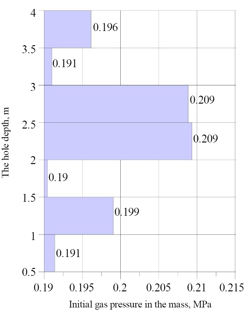
The initial velocity of gas release in the roof rocks of the KrII layer varies from 0.13 to 2.55 l/min, and the KrIII layer – from 0.12 to 0.69 l/min.
The results of mine experimental studies allowed to quantify the gas content of the free gases of the roof rocks of the mine workings drifting through the layers of KrII and KrIII and also to distinguish the intervals of the location of gas-bearing rocks in the roof rocks from the geological section. The free gases pressure values are set in the intervals of gas-bearing rocks in the roof of mine workings. The obtained experimental estimates provide a parametric basis for mathematical modeling of geomechanical processes under conditions of a near-contact accumulation of free gas.
The main methodological provisions of geomechanical analysis. The assessment of the possibility of GDP implementing in the mine working roof is based on mathematical modeling of changes in its stress-strain state and a criterion assessment of rock breakdown during the development of gas-saturated inhomogeneous layered rock mass [6].
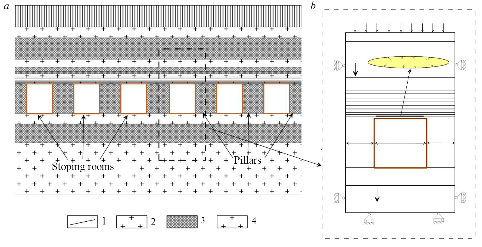
The rock mass lamination along the boundaries of layers and clay interlayers occurs due to roof deformation during excavation behind the front of stoping operations. When one or more clay contacts open, gas from the surrounding mass migrates into the formed cavity (Fig.2). The measurement results show that the gas pressure in the open contact exceeds the atmospheric pressure in the mine working, which means that it makes an additional contribution to the roof fall. It is obvious that for any mining and geological conditions and physical and mechanical properties of rocks, it is possible to determine the maximum gas pressure P in the opened contact, at which the GDP can be realized.
When analyzing the stress-strain state of the under-worked layer, the irreversible nature of salt rocks deformation was described by the model of an ideal elastic-plastic medium with internal friction. The parabolic envelope of Mohr circles was used as a yield criterion in the compression area [21]. Then the condition for localization of plastic deformations is the fulfillment of the equation
in the tension area
where τmax = (σ1 – σ3)/2 – maximum shear stress; σ = (σ1 + σ3)/2 – normal stress; σc – compression strength; σt – tensile strength; σ1, σ3 – the main stresses determined by the results of mathematical modeling.
Note that the zones of plastic deformations localization, as is customary in geomechanics, are identified with the processes of crack formation, respectively, due to shear and tension.
In the numerical implementation, the deformation of clay contacts between layers was modeled by Goodman joint elements [24]. The relation of the normal to contact stress σn with the corresponding deformation δn described by a linear equation
where kn – is the normal contact stiffness, for δn > 0 the contact was considered open and kn = 0 was assumed.
For tangential stresses τs, acting along the contact line, the relation to the shear strain δs was determined by a three-link piecewise linear approximation:
where ks – is the shear contact stiffness; km – is the shear contact stiffness in the softening area; kp – is the peak contact strength; τ* – is the residual strength.
Ultimate joint shear resistance (peak strength) was calculated according to the Coulomb equation:
where Cj – is the adhesion coefficient of the contact; \(\ \phi_j\) – is the angle of internal friction of the contact. Under the action of tensile stresses on the contact, it was assumed that the contact "opened" and its shear strength decreased to zero (kn = ks = 0).
The gas flow was modeled by a gradual increase of the pressure P in the open part of the contact. At each step of the pressure increment, a quasi-static problem was solved to determine the increment of displacements and stresses.
As the first condition for the rocks fall into the developed space, the exit of the tensile stresses action zone to the outcrop was assumed [14]. This criterion was implemented by a special organization of the computational iterative process: at each iteration, the finite elements adjacent to the roof boundary of the developed space were excluded (reset).
If the area of shear fracturing reaches the "opened" clay contact, the rocks fall into the developed space [6]. Consideration of this collapse criterion is also implemented in the calculation procedure by localization and subsequent exclusion from calculations of areas bounded by an "open" clay layer and zones of shear fracturing.
The accepted approaches were previously tested when modeling lamination and fall of the roof and soil of workings for the conditions of the Verkhnekamskoye and Starobinskoye potash deposits [15].
In relation to the Usolsky potash plant mine conditions, the initial room mining of the silvinite layer KrII was considered. The rooms width was 5.5 and 3.2 m. The inter-room pillars width varied from 5.8 to 8 m for room width 3.2 m and from 8.6 to 14.6 m for room width 5.5 m. Average extraction height made 5.5 m.
A specific section of the productive strata is shown in Fig.2, а. Physical and mechanical properties of salt rocks and clay layers were determined based on the results of laboratory tests (table.1) [17]. Mechanical characteristics of clay contacts were taken according to the data of specialized laboratory studies [3] (Table 2).
Table 1
Physical and mechanical properties of salt rocks
| Rock | Modulus of deformation E, GPa | Poisson ratio v | Specific weight γ, N/m3 | Compression strength σc, MPA | Tensile strength σt, MPA |
| Rock salt | 1,0-1,2 | 0,3 | 0,0215-0,0222 | 20,6 | 1,06 |
| Clay | 0,1 | 0,4 | 0,0220 | 13,7 | 0,90 |
| Sylvinite | 0,9-1,0 | 0,3 | 0,0218 | 19,6 | 0,83 |
Table 2
Characteristics of clay contacts
| Normal load σn, MPA | Shear strength τp, MPa | Deformation at ultimate strength δp, mm | Vertical displacement at ultimate strength δп, mm | Residual shear strength τ*, MPa | Shear stiffness at ultimate strength ks, GPa/m | Stiffness softening km, GPa/m |
| 2 | 1,60 | 0,98 | 0,14 | 1,29 | 1,63 | 0,06 |
| 3,5 | 2,17 | 1,21 | 0,29 | 1,79 | 1,79 | 0,08 |
| 5 | 2,93 | 1,27 | 0,25 | 2,62 | 2,31 | 0,13 |
| 10 | 5,12 | 2,00 | 0,51 | 4,91 | 2,57 | 0,10 |
At this stage of the analysis, we considered an extended stoping room located in the zone of full underworking (Fig.2). This allowed limiting the two-dimensional presentation of the problem and significantly reduce the amount of computational resources when the problem was symmetrical.
The worked-up salt layer was under the mass forces influence with the intensity γi (γi – the rocks density). At a distance of 3m (m – is the extracted height) above the room roof, the rock mass was replaced by the weight of the overlying thickness, which significantly reduced the size of the calculated area and, accordingly, reduced the time spent on mathematical modeling. Zero horizontal displacements were set on the side boundaries, and vertical displacements were assumed to be equal to zero on the lower boundaries.
Numerical implementation was performed by the finite element method in displacements [18] with discretization of the considered area into first-order triangular elements. The finite element solution of the elastic-plastic problem was based on the secant matrix method [12].
The mechanism for implementing GDP when opening a single contact. The nature of mine roof fall due to the one clay contact opening and the increase of the gas pressure in it, is shown on the example of stoping room with the width of 5.5 m and the pillar width of 8.6 m (Fig.3). The distance from the contact to the mine roof is 0.9 m. When the contact is opened and there is gas pressure in it, there is a slight rocks fall from the central part of the roof. In the edge parts of the opened contact, an area of fracturing begins to form due to the action of tensile stresses (Fig.3, a). With increasing pressure (Fig.3, b) an area of destructive tensile stresses develops from the contact to the room roof. At this stage, there is no further rocks fall from the mine roof. Precritical condition (Fig.3, c) is characterized by a significant expansion of the fracture area around the contact, it is "growing" not only towards the mine working, but also up to the section, and also localization of the destruction in the zone of maximum contact opening (the central part of the contact). At this point, the roof rocks fall of the mine working is again observed. After the fracture zone reaches the boundary of the developed space, a mass roof rocks fall occurs Fig.3, d).
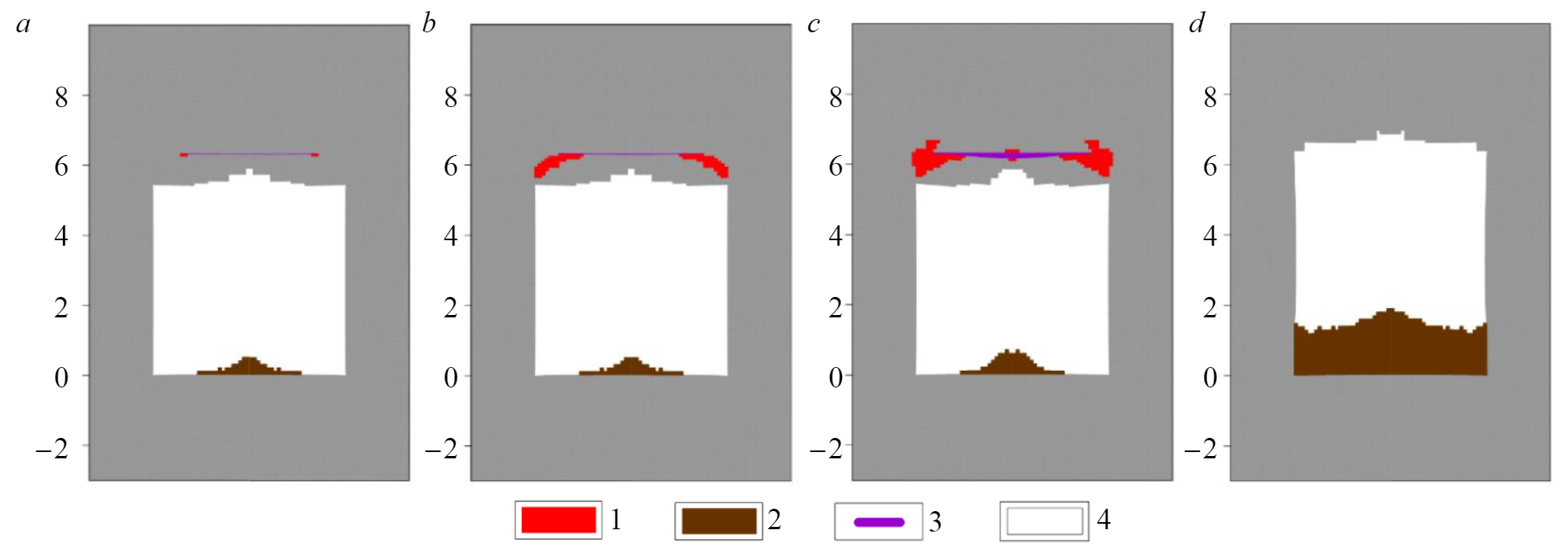
Due to the roof fall to the clay contact, the stress-strain state of rocks in the vicinity of the room instantly changes, which can lead to the fall of rocks lying above the clay layer. As the distance from the roof to the opened contact increases, the intensity of the possible fall increases. At the same time, due to an increase in the critical pressure required for the GDP implementation, the probability of a sudden release decreases (Fig.4). As it can be seen from Fig.4, a decrease in the room span leads to a significant increase in P, which is necessary for the implementation of a sudden roof rocks fall. Changing the pillars width, as shown by the calculations, does not have a significant impact on the risk of GDP implementing. For example, the critical gas pressure in a contact lying at a distance of 0.9 m from the roof, with a room width of 5.5 m, is about 1 MPa for both an 8.6 m wide pillar and a 14.6 m wide pillar. When working out the stoping rooms with the Ural 61-A combine (a = 3,2 m) at the same distance to the contact, the pressure is at the level of 2 MPa with a width of 5.8 and 8.0 m.
Modeling of the GDP formation in multi-tiered roof lamination. When estimating lamination by multiple contacts, the most prominent clay interlayers and layer boundaries typical for the productive geological section of the Usolsky potash plant mine were integrated into the model.
According to the results of measurements of the free gases pressure in the roof rocks, there are no regularities in the distribution of this parameter from the distance to the roof (see Fig.1). Thus, with multiple lamination, the pressure increase in all open contacts was assumed to be constant.
An obvious condition for the GDP formation in a clay layer is its opening, only after that gas from the surrounding mass can begin to migrate into the clay contact. This means that, all other things being equal, the intensity of lamination in the roof can serve as an indicator of the possibility of GDP formation.
Multivariate calculations have shown that the intensity of lamination along the clay contact and layer boundaries primarily depends on the rooms width. With a room width of 5.5 m (Fig.5), for the conditions of the Usolsky potash plant mine, lamination can occur to a height of up to 3.5 m above the roof of the mine working, which significantly increases the probability of a large sources of GDP formation. At the same time, changing the pillar width practically does not affect the intensity of the lamination.
The roof falls of the mine working due to the gas pressure increase during multi-tiered lamination (Fig.6) at the initial stage, is similar to the GDP implementation when one contact is opened: in the edge parts of the opened contact closest to the roof, a fracture area begins to form due to the action of tensile stresses (Fig.6, a). With increasing pressure (Fig.6, b) the area of destructive tensile stresses develops from the contact to the room roof and its "grow" up to the section occurs. At this stage, the nature of the rocks destruction in the roof of the mine workings is indistinguishable from the single contact discussed above due to the fact that the pressure in it restrains the lamination of the above-lying contacts. After the fracture zone reaches the roof of the mine working, the roof rocks fall occurs (Fig.6 c), the fall is limited by the last contact to which the fracture zone has spread. This causes the intensification of lamination in the overlying clay layers and even the opening of previously completely closed contacts (Fig.6, d), which leads to further roof fall up to the formation of a stable or relatively stable state (Fig.6, d).It is obvious that the roof in fig.6, d is in a relatively stable state only according to the formal procedure of numerical calculations. Successive falls of layers occur in instant mode. The states shown in Fig.6, c, d, e, are realized simultaneously one after the other when the critical gas pressure is reached.
The obtained character of a multi-tiered GDP formation, namely, the dominance of the open contact closest to the development at the stage before the fall, is confirmed by the similarity of the previously obtained curves of the dependence of the critical gas pressure on the distance to the open contact (see Fig.4) and graphs of the dependence of the critical pressure on the distance to the first opened gas-saturated contact in multi-tiered lamination (Fig.7). This allows to extend the obtained regularities in the GDP implementation for a single contact opening to the case of a multi-tiered lamination.
Conclusion.
Multivariate geomechanical mode-ling of the process of GDP formation and assessment of the conditions that determine the prerequisites for sudden salt and gas outbursts from the roof of mine workings allowed to obtain the following results:
1. The presence of clay contacts in the roof of the mine working can lead to the GDP formation in them, followed by the rock fall into the developed space.
2. The main factors that determine the possibility of GDP implementing are: additional gas pressure at the contact, the width of the mine working span and the distance from the roof to the first gas-saturated contact. At the same time, the width of the inter-room pillars does not significantly affect the GDP risk.
3. With multi-tiered lamination of roof rocks, there is a risk of a large sources of GDP formation. In this case, the mechanism of successive layers fall is implemented, which occurs in an instant mode.
4. 4. The intensity of lamination in the roof of the mine working, even without the influence of the gas factor, allows to give recommendations for depth of preventive degassing boreholes drilling.
References
- Andreiko S.S., Ivanov O.V., Nesterov E.A. The suppression of gas-dynamic phenomena in the development of the Verkhnekamskoye and Starobinskoye potash salt deposits. Nauchnye issledovaniya i innovatsii. 2009. Vol. 3. N 4, p. 34-37 (in Russian).
- Andreiko S.S., Kalugin P.A., Shcherba V.Ya. Gas-dynamic phenomena in potash mines: Genesis, forecast and management: Monograph. Minsk: Vysheishaya shkola, 2000, p. 335 (in Russian).
- Baryakh A.A., Asanov V.A., Pankov I.L. Physical and mechanical properties of salt rocks of the Verkhnekamskoye potash deposit. Perm: Izd-vo PGTU, 2008, p. 199 (in Russian).
- Zemskov A.N., Kondrashev P.I., Travnikova L.G. Natural gases of potash deposits and measures to control them. Perm: Tipografiya kuptsa Tarasova, 2008, p. 414 (in Russian).
- Kovalev O.V., Livenskii V.S., Meshcheryakov V.V. Safe mining specifics of potash deposits. Minsk: Polymya, 1982, p. 96 (in Russian).
- Baryakh A. A., Shumikhina A. Yu., Toksarov V. N., Lobanov S. Yu., Evseev A. V. Criteria and Peculiarities of the Bedded Roof Failure During Mining of Verchnekamskoe Potash Deposit. Gornyi Zhurnal. 2011. N 11, p. 15-19.
- Laptev B.V. Prevention of gas-dynamic phenomena in potash mines. Moscow: Nedra, 1994, p. 142 (in Russian).
- Litvinovskaya N.A., Bobrov D.A. Studies in various geological and mining conditions of the dynamics of changes over time of the free gases pressure in the soil rocks of opening workings in the mines of JSC «Belaruskali»». Strategiya i protsessy osvoeniya georesursov: Sb. nauch. tr. Iss. 16; Gornyi institut Uralskogo otdeleniya RAN. Perm, 2018, p. 320-323 (in Russian).
- Litvinovskaya N.A. Results of studies of gas content and gas dynamic characteristics of the IV potash horizon in the area of opening slopes of the 2RU mine field of PJSC «Belaruskali». Gornoe ekho. 2019. N 2(75), p. 79-82. DOI: 10.7242/echo.2019.2.19 (in Russian)
- Barbikov D.V., Andreiko S.S., Ivanov O.V., Bobrov D.A. Gas dynamics of rock mass at the Krasnoslobodsk fault. Gornyi Zhurnal. 2018. N 8, p. 38-42. DOI: 10.17580/gzh.2018.08.04
- Proskuryakov N.M., Kovalev O.V., Meshcheryakov V.V. Management of gas-dynamic processes in potash ore layers. Moscow: Nedra, 1988, p. 239 (in Russian).
- Fadeev A.B. Finite element method in geomechanics. Moscow: Nedra, 1987, p. 221 (in Russian).
- Anon K. Potash Mining in the Werra District. Phos. & Potas. 1973. N 64, p. 37-40.
- Baryakh A.A., Fedoseev A.K. Sinkhole Formation Mechanism. Journal of Mining Science. 2011. Vol. 47. Iss. 6, p. 404-403. DOI: 10.1134/S1062739147040022
- Andreiko S., Baryakh A., Lobanov S., Fedoseev A. Geo Mechanical Estimation of Danger of Gas-Dynamic Failure During Potash Deposits Mining. Procedia Engineering. 2017. Vol. 191, p. 954-961. DOI: 10.1016/j.proeng.2017.05.266
- Hedlund F.H. The extreme carbon dioxide outburst at the Menzengraben potash mine 7 July 1953. Safety Science. 2012. Vol. 50. Iss. 3, p. 537-553. DOI: 10.1016/j.ssci.2011.10.004
- Baryakh A.A., Dudyrev I.N., Asanov V.A., Pankov I.L. Interaction of layers in salt deposit. 1. Mechanical properties of joints. Journal of Mining Science. 1992. Vol. 28. Iss. 2, p.145-149.
- Khoei A.R. Extended Finite Element Method: Theory and Applications. Hoboken, New Jersey, 2015, p. 584.
- Rauche H. Die Kaliindustrie im 21. Jahrhundert: Stand der Technik bei der Rohstoffgewinnung und der Rohstoffaufbereitung sowie bei der Entsorgung der dabei anfallenden Rückstände. Springer Vieweg, 2015. p. 560.
- Siemann M.G., Ellendorff B. The composition of gases in fluid inclusions of late Permian (Zechstein) marine evaporites in Northern Germany. Chemical Geology. 2001. Vol. 173, p. 31-44. DOI: 10.1016/S0009-2541(00)00266-7
- Zhigalkin V.M., Usoltseva O.M., Tsoi P.A., Luzhanskaya T.A., Rychkov B.A. Tracing of stress circle envelope based on the calculation and experiment data. Journal of Mining Science. 2010. Vol. 46. Iss. 6, p. 612-620. DOI: 10.1007/s10913-010-0078-6
- Trubetskoy K.N., Iofis M.A., Esina E.N. Geomechanical Service in Mining under Gas-and-Dynamic Phenomena. Journal of Mining Science. 2015. Vol. 51, p. 506-512. DOI: 10.1134/S1062739115030114
- Wriggers P., Nackenhorst U. Analysis and Simulation of Contact Problems. Berlin – Heidelberg: Springer, 2006, p. 398. DOI: 10.1007/3-540-31761-9
- Wriggers P. Computational Contact Mechanics. Berlin-Heidelberg: Springer, 2006, p. 521. DOI: 10.1002/0470091355.ecm033