
Alternative frameworks for equipment positioning in mining operations
- 1 — Ph.D. Head of Laboratory Federal Research Center of Coal and Coal Chemistry of Siberian Branch of the RAS ▪ Orcid ▪ Elibrary ▪ Scopus ▪ ResearcherID
- 2 — Researcher Federal Research Center of Coal and Coal Chemistry of Siberian Branch of the RAS ▪ Orcid
- 3 — Ph.D. Senior Researcher Federal Research Center of Coal and Coal Chemistry of Siberian Branch of the RAS ▪ Orcid
Abstract
The purpose of the work is to review and consider alternative frameworks for object position determination, including for solving dispatching and navigation tasks in technological areas for the operation of highly automated autonomous vehicles without the use of satellite navigation equipment. The main problems associated with the use of satellite navigation equipment for the positioning of vehicles equipped with an automated driving system, as well as loading equipment interacting with them, are considered. The promise and relevance of developing alternative systems and methods for positioning the automated transport component during open-pit mining are shown. The review of technologies is presented, confirming the concept of current research direction related to the digital transformation of the mining industry, ensuring the positioning and position determination of mining equipment at mining enterprises without the use of satellite navigation means. An analysis of existing solutions, their advantages and disadvantages, is carried out. It is proposed to implement the solution to the problem based on machine vision algorithms, the radio direction-finding method, and laser range finding means. Options for the interaction of auxiliary and correcting devices in solving the problems of object orientation in a local coordinate system are provided. The results of field and laboratory studies of radio direction-finding and machine vision methods are presented. A patented, detailed algorithm for determining object coordinates in a designated area, developed by the authors, is described; based on this algorithm, a method for determining the position of loading equipment when interacting with transport vehicles equipped with an automated driving system without the use of global navigation satellite systems is proposed.
The work was carried out within the framework of the State assignment of the Federal Research Center of Coal and Coal Chemistry of Siberian Branch of the RAS, project FWEZ-2024-0025 “Development of scientific foundations for the creation of autonomous and automated mining machines, equipment, technical and control systems based on promising digital and robotic technologies (prolongation)” (N 125013101207-7).
Introduction
Open-pit mining with truck haulage is characterized by high operational costs compared to other methods of mineral deposit development. For instance, loading and hauling operations alone can account for up to 40 % of all costs per unit volume of mined mineral [1]. Climatic conditions and hazardous factors associated with open-pit mining [2] lead to a shortage of qualified personnel at mining enterprises. In response to this situation, mining companies in the Russian Federation and abroad are striving to reduce dependence on the human factor through the automation of the haulage technological process, which can increase the productivity of the haulage component by up to 30 % [3]. According to published data, by the second quarter of 2022, a fleet of more than a thousand haul trucks equipped with an automated driving system (ADS) was in operation worldwide. Forecasts indicate that the number of haul trucks equipped with such systems globally will only increase [4, 5], and by the second half of 2026, the market volume for such mining equipment will exceed 4 billion dollars, confirming the relevance of developing the ADS and its components for quarry transport [6].
An important condition for the effective operation of quarry mining equipment equipped with ADS is its precise positioning within the automated area, which is closely related to localization and routing [7, 8]. Currently, modern ADS and dispatching systems perform position determination of controlled objects using global navigation satellite systems (GNSS), such as the American Global Positioning System (GPS) and the Russian Global Navigation Satellite System (GLONASS) [9-11]. With ground infrastructure, GPS can provide positioning accuracy of up to several tens of centimeters; however, without ground infrastructure, the positioning accuracy decreases to 15-20 m. For GLONASS the declared error in the position determination of stationary objects using ground infrastructure is 1 m.
However, there exists a number of industrial and technological positioning tasks for which the solution by conventional methods is inefficient. These include positioning for open-underground mining technological processes, as well as operation in northern regions with an unstable satellite signal level [7, 12, 13]. It is known that in the Arctic and Antarctic, satellite navigation systems have errors in the position determination of objects [7, 12, 13]. At the same time, these territories possess significant mineral reserves [14-16] and are a priority for development.
Despite the advantages of GNSS, the application of the system has a number of features that can be considered disadvantages. Specifically, these include the necessity of ground infrastructure for high accuracy, as well as the low power of the signal received from satellites in conditions of insufficient coverage. For example, on average, the GPS signal power at the earth’s surface is only –160 dB (1 W) [17], which makes it vulnerable to intentional jamming [18-20]. The signal can be completely jammed or spoofed, in which case the navigation equipment will determine incorrect coordinates [17, 21]. Furthermore, signals from satellite navigation systems can be distorted and lost without external influence due to the effect of metal structures and terrain relief [22-24].
The aim of the research is to review and consider alternative frameworks for the position determination of objects, including for solving dispatching and navigation tasks within the technological process areas of highly automated mining equipment without the use of navigation equipment. The development and implementation of alternative methods for the position determination and navigation of mining equipment with an ADS are relevant scientific and technical tasks [7, 20, 25].
Methods
The literature describes the application of optical [26, 27] and non-optical [26, 28, 29] methods for solving the task of spatial orientation of objects in a local coordinate system. However, a detailed consideration of the application options of these methods for the positioning of mining equipment with an ADS requires an analysis of the interaction between the elements of the excavator – truck system during loading. One of the main conditions for achieving maximum productivity of technological process areas for the operation of highly automated mining equipment is the coordinated work of the excavator and the haul truck. For this purpose, there exists a methodology for the approach and positioning of a haul truck with an ADS, which regulates the spatial and temporal parameters of the process to rationalize the loading cycle and ensure safety. The methodology supports the rationality of the positioning configuration, has a recommendatory nature, and is based on an analysis of industrial practice and standard schemes. A key parameter is the orientation of the haul truck parallel to the pit face axis. This arrangement minimizes the time for approach and positioning for loading, as well as the rotation angle of the excavator’s boom. Furthermore, positioning is carried out on the right side of the excavator, which ensures safe loading from the side or from behind. Although positioning the haul truck at an angle to the pit face axis may in some cases reduce the boom rotation angle, this configuration is not rational, as it increases the duration and complexity of vehicle maneuvering, negating the potential time savings. The orientation of the haul truck parallel to the pit face axis allows for the standardization of the truck’s trajectory in the loading zone, as well as for the automatic determination of the excavator’s position based on the application of object spatial orientation methods.
Among the alternative methods for the position determination of objects for dispatching and routing in transport sections, two approaches can be distinguished – determining the object’s position on the ground (using a dedicated area of known size referenced to an object on the ground) and in geodetic coordinate systems, such as WGS-84, PZ-90, and their analogs [30]. In this case, the object’s coordinates can be linked to coordinates in geodetic coordinate systems.
From the set of methods ensuring the position determination of objects in geodetic coordinate systems, one can distinguish astronomical navigation [31], object identification on the ground using machine vision [7, 32] and real-time positioning systems based on wireless data transmission technologies [33-35].
Astronomical navigation is one of the oldest methods for the position determination of objects. In the modern world, astronomical navigation is used as a backup method for position determination at sea and in the air [31]. Progress in the field of machine vision, the increase in computational power of compact computers, and the search for solutions to replace GNSS in zones of unstable operation have renewed researchers' interest in astronomical navigation. As a result, prototypes began to appear, combining methods of astronomical navigation and machine vision, embodied in compact, low-cost devices [20].
Position determination of objects by their identification on the terrain using machine vision is a group of methods with various approaches, to both the collection and formation of a database of objects on the earth’s surface, the recognition of which is necessary for position determination, and to the detection and identification of objects [7, 32]. In general, this group of methods allows for extracting an object with precisely known coordinates in geodetic coordinate systems from a video data stream and referencing the position of the unmanned autonomous vehicle from which the observation is conducted by the machine vision system to it [7, 32].
Among the real-time positioning methods based on wireless data transmission technologies, position determination via triangulation of GSM communication base station signals can be highlighted as the primary one [33], whereas other methods within this group are more often used for position determination in local coordinate systems [36-38]. In such systems, measurements of signals from Wi-Fi network access points [39-41], Bluetooth transmitters, Active RFID, and UWB [36, 37] are used for position determination of objects. Combined methods based on machine vision are also applied [42, 43].
The implementation of position determination methodologies in a local coordinate system, based on measuring the signal from Wi-Fi access points; Bluetooth, Active RFID, and UWB transmitters, has several approaches, and all of them are generally based on measuring signal power [35, 41, 44]. In [41], an approach is presented where preliminary recording of signal parameters in each square of the local coordinate system is performed, and in [35] the authors indicate that the distance to a Wi-Fi network access point installed at a location with known coordinates is calculated based on the power of the detected signal.
With the use of mechanical measuring instruments for celestial navigation and conducting all measurements manually, an accuracy of approximately 1 nautical mile (1852 m) or ±1 angular minute is achieved [31, 45], which is used in maritime and air transport as a backup method for vessel position determination. The application of modern technologies, such as machine vision and neural network image analysis, has allowed for the development of a compact celestial navigation device based on a modern single-board computer without the use of complex mechanical and optical systems; the theory and operating principles of which are described in [46, 47]. A functional prototype of a celestial navigation device with positioning accuracy almost two times higher than when using the manual method (1050 m) is described in [20]. Furthermore, the NAS-14V2 navigation system, developed in the USA in the 1960s, which allowed for determining coordinates using celestial navigation with an accuracy of up to 90 m, is known and described in the literature [48]. Despite progress, over centuries of application, the method of position determination by the location of celestial bodies does not allow achieving accuracy comparable to GNSS and has a serious drawback for use on ground transport – the necessity of constant visibility of the celestial bodies in the sky, by whose position the coordinates of the object being positioned are determined [20].
Different approaches are practiced for the position determination of unmanned autonomous vehicles using machine vision methods in areas with known coordinates. In [32], the authors propose forming a database of objects for identification using satellite imagery, which remain in large volumes after remote sensing of the earth’s surface from space. In [7] the authors propose creating special markers on the surface with precise reference to geodetic coordinate systems, similar to those described in [49]. An option involving equipping roads with special markers recognized by machine vision (so-called Smart roads) [50] using masks and contours [51] is also considered. At the moment, such navigation systems are under development and have significant potential for advancement [7, 32]. The universality of this group of position determination methods allows for their testing on scaled models. Machine vision has a number of application peculiarities in conditions of a constantly changing environment due to the necessity of determining the coordinates of stationary, unchangeable objects; however, it demonstrates effectiveness when working in conjunction with auxiliary guiding and adjusting devices and systems [25, 43].
Another group of alternative methods for position determination of objects is real-time positioning based on wireless data transmission technologies. For determining the coordinates of an object (in the case of a cell phone or modem) in geodetic coordinate systems, only methods based on studying signals from GSM communication base stations are well-suited [33], predominantly, methodologies built on the triangulation of GSM communication base station signals are used [33].
The application of methods based on Bluetooth technology reduces the error in object positioning to 1-2 m [35, 41]. Similar error rates are provided by Active RFID technology – 2 m [35, 41]. The most accurate solution with an error of about 0.3 m is the method based on the use of UWB technology [35, 41]. At the same time, the operating range relative to the base station is less than 100 m for all the listed methods [35, 41], which is insufficient for their use in the ADS. As of 2025, the possibility of using UWB-based methods within the territory of the Russian Federation has not been officially confirmed by the State Commission for Radio Frequencies.
As a result of analyzing the features of methods permissible for hardware implementation in the ADS, their advantages and disadvantages have been identified from the perspective of application in the mining industry for solving tasks of dispatching and navigation within technological process sections for the operation of highly automated vehicles without the use of navigation equipment. Based on existing methods, an original approach to the position determination of machinery at mining enterprises using a combination of radio direction finding, machine vision, and laser rangefinding is proposed. Conceptually, the approach consists of the sequential application of radio direction-finding equipment and a machine vision system for devices determining the position of a moving object relative to a stationary one within a local coordinate system, followed by the application of laser rangefinding means and the determination of angular movements.
Discussion
The task of determining the coordinates of an excavator is a technological process requirement aimed at reducing downtime and increasing the readiness factor of mining equipment for open-pit operations. The input data for solving the research problem was the requirement to ensure a positioning error of no more than 1 m for every 200 m of distance to the moving object (excavator), moving within an allocated local site of limited size relative to a stationary one (the mast of the entrance gate). For the site to which the local coordinate system is applied, restrictions have been established – the site where navigation is carried out has a flat surface (designed in accordance with the requirements of regulatory documentation) and a slope of no more than 5 %. Significant elevation differences of the site’s surface exceeding standard values can lead to an increase in error and the failure of the proposed approach.
To solve the problem, a local coordinate system associated with a stationary object, relative to which the coordinates of the moving one were determined, was introduced. Taking into account the assumption that the allocated site is flat and has no elevation changes, a Cartesian coordinate system is proposed for the local site. Since the task of position determination is considered in the context of controlling a vehicle by the ADS, the entrance gate to the site is defined as the stationary object relative to which the coordinates of the moving object are determined. The entrance gates consist of two masts installed on the right and left sides of the technological process road used for entering the site, such that the line drawn through the centers of the entrance gate masts is strictly perpendicular to the road surface.
The entrance gate masts are the reference points for the local coordinate system on the site. Thus, a virtual grid with the required step is superimposed on the entire site. The virtual abscissa axis passes through the center of each gate mast. The intersection point of the abscissa and ordinate axes is chosen so that the entire site is located in the first quadrant of the coordinate plane formed by the virtual axes. The distance from the intersection point of the virtual coordinate axes to the center of the entrance gate mast, from which the hypotenuse of the right triangle will be constructed, is set when building the virtual axes.
A graphical method for solving the analytical problem was applied for determining the coordinates in the Cartesian system. The sequence of actions when determining the coordinates of a moving object in the Cartesian coordinate system inscribed in the allocated local site is demonstrated in Fig.1.
Using the graphical method, it is shown that any point located in the first quadrant of the coordinate plane and not belonging to the coordinate axes can be the vertex of a right triangle, one side of which will be located on the virtual abscissa axis. Then the hypotenuse of this triangle will be the segment laid from the center of one of the masts to the point whose coordinates need to be determined. After measuring the angle between the hypotenuse and the abscissa axis, the lengths of the two unknown legs are calculated based on the properties of a right triangle. Then the coordinate of the point in the local coordinate system will be the distance from the intersection point of the coordinate axes to its projection on the axes. Thus, to determine the coordinate of a point on the local site, it is necessary to measure the hypotenuse and the angle between the hypotenuse and the virtual abscissa axis, which forms two measured quantities.
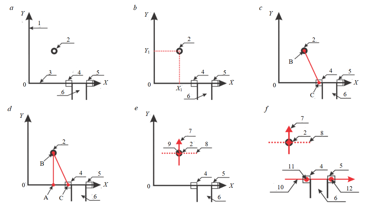
Fig.1. Sequence of determining the coordinates of a moving object in the Cartesian coordinate system on a designated local area: a – location of the virtual coordinate axes and the entry gate masts relative to the haul road; b – example of determining the coordinates of a moving object (coordinates X1, Y1); c – location of the hypotenuse CB of the virtual triangle between the coordinate determination devices; d – location of the virtual lines AB and AC (coordinates of the moving object); e – example of the encoder’s zero point location on the moving object in the coordinate determination device; f – example of the zero position of the encoder of the coordinate determination device in the entry gate mast
1 – virtual axis 0Y; 2 – moving object; 3 – virtual axis 0X; 4 – left entry gate mast; 5 – right entry gate mast; 6 – haul road; 7 – zero position of the coordinate determination device's encoder on the moving object; 8 – longitudinal axis of the moving object; 9 – location of the coordinate determination system’s encoder on the moving object; 10 – zero position of the coordinate determination device’s encoder in the left entry gate mast; 11 – location of the coordinate determination system’s encoder in the center of the left entry gate mast; 12 – center of the right entry gate mast
The distance between the object, whose coordinates need to be determined, and the entrance gate mast is proposed to be measured using the laser rangefinding method, which can provide a measurement error at a distance of 200 m of less than 0.005 m for modern device models. Also, Fig.1, d allows us to understand that the greatest error in determining the coordinates of a moving object is caused by the resolution of the encoder when measuring angle ACB. In this regard, to determine the sufficient accuracy of the encoder, the maximum deviations of the projection values of point A when measuring angle ACB were calculated, and a diagram of the dependence of these deviations in the calculated size of segment AB (coordinate of the 0Y axis) on the resolution of the encoder at a distance of 200 m to the moving object was obtained (Fig.2). It should be considered that the cost of an encoder increases depending on its resolution – the number of measurement points (equal steps) per one revolution.
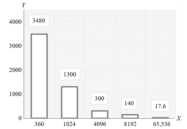
Fig.2. Plot of projection value deviations of point A when measuring angle ACB in the calculated length of segment AB (0Y axis coordinate) on the encoder resolution at a distance of 200 m to the moving object; X – typical resolution values of commercially available absolute encoders, steps per revolution; Y – maximum deviation from the calculated distance to the moving object between encoder steps at 200 m range, mm
The values of the second measured quantity – the angle between the abscissa axis and the hypo-tenuse of the triangle – are proposed to be measured by an absolute encoder using an opto-mechanical measurement method, where a unique digital position code is provided for each shaft position, read by an optical system from a code disk.
Subsequently, based on the obtained angle value and the distance to the object measured by the laser rangefinder, the calculation of the object’s coordinates X and Y is performed.
The radio direction-finding method and machine vision, when applied sequentially, allow for orienting a motorized platform equipped with a laser rangefinder and an absolute encoder for measuring the described quantities (the hypotenuse of the right triangle and the angle between the hypotenuse and the leg lying on the abscissa axis).
An array of sensitive photodiodes is installed on the moving object, onto which the laser rangefinder beam is directed. To simplify the operation of machine vision algorithms, it is proposed to install bright point light sources as markers along the perimeter. The radio direction-finding method is used for the primary targeting of the motorized platform, which includes a laser rangefinder and a video camera of the machine vision system. This approach allows for a significant reduction in the region of interest for machine vision. It should be considered that weather conditions can introduce distortions into the results and require the development of additional measures and technical means to compensate for their influence. If one of the components fails, an alarm signal must be generated by the self-diagnostic means.
An experimental verification of the proposed concept was carried out in simulated conditions. Field studies related to radio direction-finding measurements were conducted in an open area, located more than 40 km from the city boundary, outside the influence zone of high-voltage power lines and cellular operator base stations, according to the following methodology:
- Installation of the receiving device in the line of sight of the transmitting device.
- Measurement of the accuracy characteristics of the azimuth deviation of the signal’s angle of arrival for distances from 1 to 50 m using amplitude modulation, binary phase-shift keying, and quadrature phase-shift keying.
- Execution of a right turn and assessment of the deviation direction from the transmitting module. Measurement of the accuracy characteristics of the azimuth deviation of the signal’s angle of arrival for distances from 1 to 50 m using amplitude modulation, as well as binary phase-shift keying and quadrature phase-shift keying.
- Return of the receiving device to the line-of-sight zone. Measurement of the accuracy characteristics of the azimuth deviation of the signal’s angle of arrival for distances from 1 to 50 m using amplitude modulation, binary phase-shift keying, and quadrature phase-shift keying.
- Execution of steps 1-4 when moving the receiving device to the left.
Figure 3 shows the direction-finding spectra of signal direction angles in the binary phase-shift keying operation mode. A phased antenna array consisting of four whip antennas was used during the experiment. The angle values were obtained based on the method of signal phase difference on each receiving antenna using the MUSIC (MUltiple SIgnal Classification) algorithm. The results of the accuracy characteristics for the used modulation types are presented in the Table.
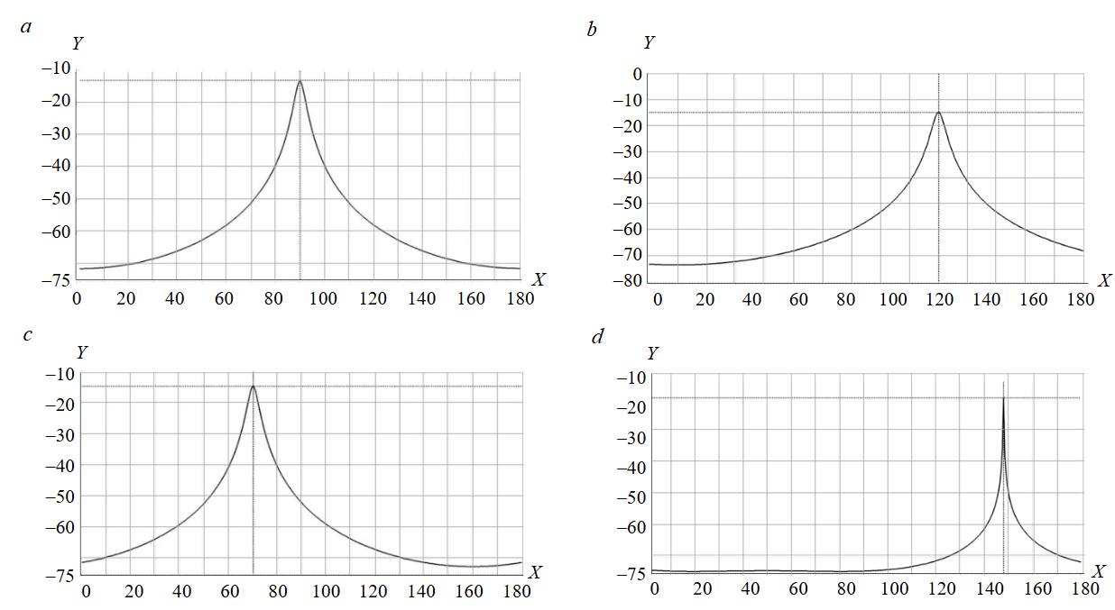
Fig.3. Front panel views during field studies: a – direct line of sight to the object, azimuth 90°; b – object located to the right at a 120° angle; c – object located to the left at a 70° angle; d – object located at a 148° angle; X – signal strength, dBm; Y – directional spectrum of the signal arrival angle, deg
During the experiment, a periodic deviation of the angle azimuth in the range from 35 to 50° for amplitude modulation and from 10 to 15° for quadrature phase-shift keying generation was observed. The distance from the receiving device to the stationary signal source transmitting device varied from 1 to 50 m, while the accuracy characteristics of the angle azimuth deviation for binary phase-shift keying changed within deviations of 5-7°. This method has potential in combination with machine vision for determining the coordinates of objects in a local coordinate system.
Furthermore, during the conducted experiments under laboratory conditions, testing of the positioning of the machine vision camera relative to a marker with installed point light sources – coordinate positioning markers (CPM) – was carried out. The marker image represents a geometric shape (a circle) and, from the standpoint of machine vision methods, is a vector gradient at the contour points [29] with distinctly bright pixels inside the contour. The Hough transform algorithm was chosen as the most accurate tool for determining the geometric correspondence of contours (Shape Detection) to the given shape.
Modulation types accuracy characteristics
|
Distance to signal source, m |
Radio signal source angle azimuth, deg |
||||
|
Modulation type |
|||||
|
Amplitude modulation |
Root mean square deviation |
Binary phase-shift keying |
Quadrature phase-shift keying |
Root mean square deviation |
|
|
1 |
– |
– |
– |
– |
– |
|
2 |
35-40 |
1.87 |
5 |
10-15 |
2.02 |
|
3 |
35-41 |
2.27 |
5 |
11-15 |
1.63 |
|
4 |
32-40 |
4.85 |
5 |
9-15 |
2.44 |
|
5 |
31-39 |
3.02 |
6 |
12-16 |
1.35 |
|
6 |
32-42 |
3.84 |
5-6 |
10-15 |
1.89 |
|
7 |
32-35 |
1.05 |
3 |
11-16 |
2.02 |
|
8 |
33-36 |
1.03 |
5 |
9-14 |
1.62 |
|
9 |
39-45 |
3.36 |
6 |
10-14 |
1.58 |
|
10 |
36-47 |
4.32 |
7 |
12-15 |
1.23 |
|
20 |
33-50 |
6.36 |
6 |
12-14 |
0.88 |
|
50 |
35-50 |
6.24 |
5 |
10-12 |
0.92 |
The installation of the central coordinate point in the allocated region of the reference light markers of the light board on the video image is defined as the central coordinate, relative to which the recognition of the contours of the circles of the horizontal and vertical CPM (three on the left or right) is carried out. Figure 4 shows an example of the image processing sequence when determining the contours of the circles of the coordinate markers and their quantity under an illumination of 300 lm from a distance of 8 m by an NI 1742 Smart Camera with the following characteristics: matrix type – monochrome CCD, resolution – 640×480 pixels, pixel size – 7.4·10–6 m by 7.4·10–6 m, lens aperture – F/1.4.
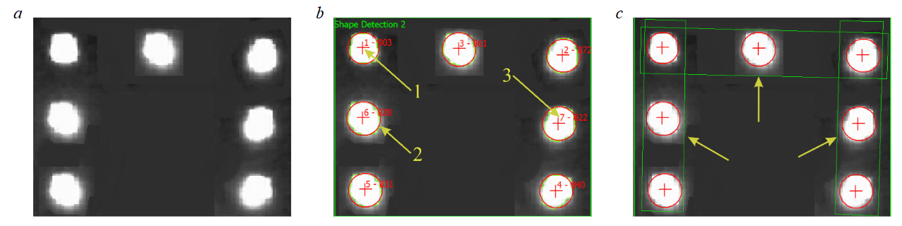
Fig.4. Image processing sequences for CPM recognition: a – binarization of the original image (extraction of gray tones); b – the CPM image after processing with Hough algorithms; c – the result of determining horizontal and vertical correspondences1 – recognized circle centers; 2 – recognized circle contours; 3 – determination of the CPM quantity
The process of checking the position of the CPM control points horizontally and vertically by the machine vision system determines them so that the quantitative composition of all markers is within the rectangular area of the region of interest, both horizontally and vertically.
The control position is determined based on the region of interest, a rectangular allocated area in the video data stream. Accordingly, if the control position of the point light sources is determined with horizontal deviations, it is shifted by a specified angle. The control position of the point light sources is checked vertically in the same manner. A fragment of determining the CPM control position is shown in Fig.5. This is how the precise targeting of the laser rangefinder and the rotation of the absolute encoder shaft towards the marker installed on the moving object is performed.
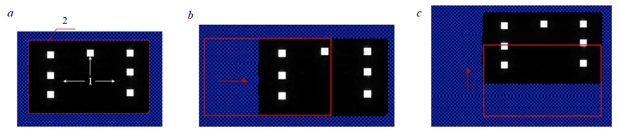
Fig.5. Verification of the reference position of point light sources by the machine vision system: a – reference position of the CMP; b – horizontal region of interest definition; c – vertical region of interest definition1 – reference position of the fiducial markers; 2 – rectangular region of interest
The described method of position determination is shown in Fig.6 as an algorithm, where: S1 – start; O1 – construction of virtual coordinate axes; O2 – preparation and startup of the position determination devices; O3 – determination of the bearing to the moving object; D1 – decision “Bearing to the moving object found?”; M1 – message “Error in bearing detection. Repeat search?”; Mi1 – manual input “Yes/No”; E2 – end/stop; O4 – alignment of the position determination device on the moving object and the entrance gate mast along one axis according to the bearing data using motorized drives; O5 – fine-tuning of the direction using the machine vision system data via motorized drives; O6 – precise direction adjustment using the array of sensitive photodiodes and the laser emitter via motorized drives; O7 – measurement of the segment CB (see Fig.1, c) by the laser rangefinder and the rotation angle of the laser rangefinder ACB (see Fig.1, d) by the encoder of the position determination device in the left entrance gate mast; O8 – calculation of the moving object's coordinates; Ou1 – input of the moving object's coordinates into the control system.
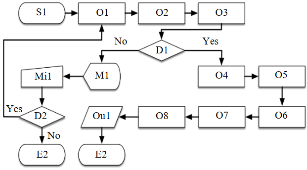
Fig.6. Algorithm for determining the coordinates of a moving object in the Cartesian coordinate system on a designated local area
Thus, the proposed approach, based on the application of a combination of machine vision methods, radio direction finding, laser rangefinding, and means for determining angular movements with sufficient resolution, allows for determining the position of equipment with a positioning error of no more than 1 m for every 200 m of distance between objects.
Conclusion
The analysis of the most common classical and alternative methods for positioning objects has shown the relevance of developing methods for the precise position determination of equipment in automated areas without the use of satellite navigation.
The proposed and described method for the mutual orientation of objects in a local coordinate system, using the example of determining the location of a stationary object relative to a moving one, which consists in using a machine vision system and a complex of auxiliary optical and direction-finding equipment by means of motorized rotary supports, allows, through the combined application of machine vision algorithms, the radio direction-finding method based on the MUSIC algorithm, and laser rangefinding means, to solve the problems of determining the coordinates of objects. Machine vision using the Hough method in recognizing CPM determines the specified number of light markers within the established region of interest.
The proposed method for the position determination of a loading machine, based on the application of machine vision methods, the direction-finding method, and laser rangefinding means, has demonstrated the operational capability of the proposed solutions. Collectively, the described solutions can be considered as a basis for building digital twins of the excavator-truck complex and can be applied to solve the problems of reducing downtime, increasing safety, and improving the transport logistics efficiency of mining enterprises.
References
- Damrin M.E. Evaluation of efficiency and increase of performance of mining equipment fleet for open pit mine operations. Transport, mining and construction engineering: science and production. 2024. N 27, p. 99-106 (in Russian). DOI: 10.26160/2658-3305-2024-27-99-106
- Burakov A.M., Panishev S.V., Alkova E.L., Khosoev D.V. Experience of using hydraulic excavators in difficult mining, geological and climatic conditions. Russian Mining Industry. 2022. N 2, p. 90-96 (in Russian). DOI: 10.30686/1609-9192-2022-2-90-96
- Klebanov D.A., Makeyev M.A., Sizemov D.N. Use of autonomous and remotely operated equipment in surface mining. Russian Mining Industry. 2020. N 6, p. 14-18 (in Russian). DOI: 10.30686/1609-9192-2020-6-14-18
- Li Zhang, Wenxuan Shan, Bin Zhou, Bin Yu. A dynamic dispatching problem for autonomous mine trucks in open-pit mines considering endogenous congestion. Transportation Research Part C: Emerging Technologies. 2023. Vol. 150. N 104080. DOI: 10.1016/j.trc.2023.104080
- Sizemov D.N., Temkin I.O., Deryabin S.A., Vladimirov D.Ya. On some aspects of increasing the target productivity of unmanned mine dump trucks. Eurasian Mining. 2021. N 2, p. 68-73. DOI: 10.17580/em.2021.02.15
- Sishi M.N., Telukdarie A. Implementation of Industry 4.0 technologies in the mining industry – a case study. International Journal of Mining and Mineral Engineering. 2020. Vol. 11. Iss. 1, p. 1-22. DOI: 10.1504/IJMME.2020.105852
- Chuprov S., Belyaev P., Gataullin R. et al. Robust Autonomous Vehicle Computer-Vision-Based Localization in Challenging Environmental Conditions. Applied Sciences. 2023. Vol. 13. Iss. 9. N 5735. DOI: 10.3390/app13095735
- Cotroneo D., Russo S., Cornevilli F. et al. Implementing positioning services over an ubiquitous infrastructure. Second IEEE Workshop on Software Technologies for Future Embedded and Ubiquitous Systems, 11-12 May 2004, Vienna, Austria. IEEE, 2004, p. 14-18. DOI: 10.1109/WSTFES.2004.1300407
- Gaber T., El Jazouli Y., Eldesouky E., Ali A. Autonomous Haulage Systems in the Mining Industry: Cybersecurity, Communication and Safety Issues and Challenges. Electronics. 2021. Vol. 10. Iss. 11. N 1357. DOI: 10.3390/electronics10111357
- Nguyen H.A.D., Ha Q.P. Robotic autonomous systems for earthmoving equipment operating in volatile conditions and teaming capacity: a survey. Robotica. 2023. Vol. 41. Iss. 2, p. 486-510. DOI: 10.1017/S0263574722000339
- Hamada T., Saito S. Autonomous Haulage System for Mining Rationalization. Hitachi Review. 2018. Vol. 67. N 1, p. 87-92.
- Akl M.N. Elements of a methodology for modernizing a satellite geodetic network in a geologically unstable area. Uspekhi sovremennogo estestvoznaniya. 2023. N 6, p. 113-121. DOI: 10.17513/use.38061
- Yastrebova A., Höyhtyä M., Boumard S. et al. Positioning in the Arctic Region: State-of-the-Art and Future Perspectives. IEEE Access. 2021. Vol. 9, p. 53964-53978. DOI: 10.1109/ACCESS.2021.3069315
- Lassila M. The Arctic mineral resource rush and the ontological struggle for the Viiankiaapa peatland in Sodankylä, Finland. Globalizations. 2021. Vol. 18. Iss. 4, p. 635-649. DOI: 10.1080/14747731.2020.1831818
- Dmitrieva D., Solovyova V. A Taxonomy of Mineral Resource Projects in the Arctic: A Path to Sustainable Financing? Sustainability. 2024. Vol. 16. Iss. 11. N 4867. DOI: 10.3390/su16114867
- Seregin S.N., Gasanova Kh.N., Tazetdinov R.R. Resource potential of the Russian Arctic: possible facets of connecting mineral resources and water bioresources. Economics, labor, management in agriculture. 2023. N 3 (97), p. 150-161 (in Russian). DOI: 10.33938/233-150
- Meggs R.W., Watson R.J. Spoofing and Jamming of GNSS Signals: Are They Real and What Can We Do About Them? Proceedings of the International Ship Control Systems Symposium (iSCSS), 6-8 October 2020, Delft, Netherlands. Institute of Marine Engineering, Science and Technology, 2020, p. 8. DOI: 10.24868/issn.2631-8741.2020.005
- Zhijun Wu, Yun Zhang, Yiming Yang et al. Spoofing and Anti-Spoofing Technologies of Global Navigation Satellite System: A Survey. IEEE Access. 2020. Vol. 8, p. 165444-165496. DOI: 10.1109/ACCESS.2020.3022294
- Cardellach E., Elósegui P., Davis J.L. Global distortion of GPS networks associated with satellite antenna model errors. Journal of Geophysical Research: Solid Earth. 2007. Vol. 112. Iss. B7. N B07405. DOI: 10.1029/2006JB004675
- Teague S., Chahl J. An Algorithm for Affordable Vision-Based GNSS-Denied Strapdown Celestial Navigation. Drones. 2024. Vol. 8. Iss. 11. N 652. DOI: 10.3390/drones8110652
- Psiaki M.L., Humphreys T.E., Stauffer B. Attackers can spoof navigation signals without our knowledge. Here’s how to fight back GPS lies. IEEE Spectrum. 2016. Vol. 53. Iss. 8, p. 26-53. DOI: 10.1109/MSPEC.2016.7524168
- von Hünerbein K. Detection and Monitoring of Jamming and Spoofing of GPS/GNSS Signals in Harbours and Industrial Areas. The European Test and Telemetry Conference, 11-13 June 2024, Nuremberg, Germany. AMA Association for Sensors and Measurement, 2024, p. 54-60. DOI: 10.5162/ETTC2024/A3.2
- Keyuan Jiao, Maozhong Song, Xiaolong Tang et al. Two-Dimensional Differential Positioning with Global Navigation Satellite System Signal Frequency Division Relay Forwarding to Parallel Leaky Coaxial Cables in Tunnel. Applied Sciences. 2024. Vol. 14. Iss. 22. N 10288. DOI: 10.3390/app142210288
- Kundiladi M.S., Rahim S.M.S.A., Rishad M.S. Secure Autonomous Vehicle Localization Framework using GMCC and FSCH-KMC under GPS-Denied Locations. Annals of Emerging Technologies in Computing. 2024. Vol. 8. N 3, p. 64-74. DOI: 10.33166/AETiC.2024.03.001
- Kizilov S.A., Nikitenko M.S., Khudonogov D.Yu. Technical implementation of a method for excavator positioning in a face without using a satellite navigation. Modern Science: actual problems of theory and practice. Series Natural and Technical Sciences. 2024. N 12-2, p. 46-52 (in Russian). DOI: 10.37882/2223-2966.2024.12-2.11
- Zakharov A.A., Tuzhilkin A.Y., Vedenin A.S. The algorithm for determining the position and orientation of three-dimensional objects from video images on the basis of a probabilistic approach. Fundamental research. 2014. N 11-8, p. 1683-1687 (in Russian).
- Nikitenko M.S., Khudonogov D.Y., Popinako Y.V. Autonomous vehicle positioning approach based on machine vision and direction finding. Modern Science: actual problems of theory and practice. Series Natural and Technical Sciences. 2023. N 12-2, p. 84-86 (in Russian). DOI: 10.37882/2223-2966.2023.12-2.20
- Molodtsov V., Kureev A. Experimental study of the applicability of the MUSIC algorithm for determining the direction of signal arrival. Informatsionnye tekhnologii i sistemy 2019 (ITIS 2019): Sbornik trudov 43-i mezhdistsiplinarnoi shkoly-konferentsii IPPI RAN, 17-22 sentyabrya 2019, Perm, Russia. Institut problem peredachi informatsii im. A.A.Kharkevicha RAN, 2019, p. 123-129.
- Korobkov M.A., Petrov A.S. Direction of arrival estimation algorithms. Electromagnetic Waves and Electronic Systems. 2015. N 4, p. 3-32 (in Russian).
- Barzegari V., Edrisi A. Optimal number and location of parking facilities in presence of autonomous vehicles. Numerical Methods in Civil Engineering. 2022. Vol. 7. Iss. 1, p. 70-83. DOI: 10.52547/nmce.2022.401
- Mostafa A. The Principles of Celestial Navigation. Arab Academy for Science, Technology & Maritime Transport, 2019, p. 211.
- Kramarov S.O., Mityasova O.Yu., Temkin I.O., Khramov V.V. Delaunay triangulation-based methodology of intelligent navigation and control of mobile objects. Mining Informational and Analytical Bulletin. 2021. N 2, p. 87-98 (in Russian). DOI: 10.25018/0236-1493-2021-2-0-87-98
- Bansal S.K. Advancements in Digital Forensics: A Quantitative Analysis of Cell Tower Triangulation Techniques. International Journal of Current Science Research and Review. 2024. Vol. 7. Iss. 10, p. 7947-7954. DOI: 10.47191/ijcsrr/V7-i10-54
- Zandbergen P.A. Accuracy of iPhone Locations: A Comparison of Assisted GPS, WiFi and Cellular Positioning. Transactions in GIS. 2009. Vol. 13. Iss. s1, p. 5-25. DOI: 10.1111/j.1467-9671.2009.01152.x
- Stewart J., Hassan M.N., Sudin S. Location Based Systems over Wi-Fi Networks: Current Challenges and Future Directions. 3rd International Conference on Advanced Materials Engineering & Technology, 4-5 December 2014, Ho Chi Minh, Vietnam. 2014.
- Lachvajderova L., Fiľo M. Real-Time Location Systems Across the Industries – Literature Review and Case Studies. Acta Mechanica Slovaca. 2024. Vol. 28. Iss. 3, p. 42-48. DOI: 10.21496/ams.2024.017
- Sullivan B.P., Ghafoorpoor Yazdi P., Thiede S. Total Cost of Ownership of Real-Time Locating System (RTLS) Technologies in Factories. Procedia CIRP. 2023. Vol. 120, p. 822-827. DOI: 10.1016/j.procir.2023.09.082
- Ermolaev V.T., Semenov V.Yu., Flaksman A.G. et al. Two-dimensional direction finding with super-resolution in an automotive MIMO radar under target correlation conditions. Elektrosvyaz. 2022. N 8, p. 45-52. DOI: 10.34832/ELSV2022.33.8.006
- Yu-Chung Cheng, Yatin Chawathe, Anthony LaMarca, John Krumm. Accuracy characterization for metropolitan-scale Wi-Fi localization. MobiSys '05: Proceedings of the 3rd international conference on Mobile systems, applications, and services, 6-8 June 2005, Seattle, WA, USA. Association for Computing Machinery, 2005, p. 233-245. DOI: 10.1145/1067170.1067195
- Bouguebrine C., Mikhailov A.V., Kazakov Yu.A. Control of excavator bucket positioning using sensors. Transport, mining and construction engineering: science and production. 2024. N 25, p. 169-175 (in Russian). DOI: 10.26160/2658-3305-2024-25-169-175
- Núñez Fernández D. Implementation of a WiFi-based indoor location system on a mobile device for a university area. 2019 IEEE XXVI International Conference on Electronics, Electrical Engineering and Computing (INTERCON), 12-14 August 2019, Lima, Peru. IEEE, 2019, p. 4. DOI: 10.1109/INTERCON.2019.8853556
- Khudonogov D.Yu., Nikitenko M.S., Kizilov S.A. Direction finding methods application for autonomous vehicles orientation in closed technological area. Modern high technologies. 2023. N 12-2, p. 239-245 (in Russian). DOI: 10.17513/snt.39888
- Kizilov S.A., Nikitenko M.S., Khudonogov D.Yu. Determining excavator location in the face relative to a dump truck issue without using satellite navigation. Modern high technologies. 2024. N 12, p. 41-47 (in Russian). DOI: 10.17513/snt.40242
- Ramtohul A., Khedo K.K. Mobile Positioning Techniques and Systems: A Comprehensive Review. Mobile Information Systems. 2020. Vol. 2020. N 3708521. DOI: 10.1155/2020/3708521
- Venkat R. Challenges to overcome limitations of human centric practices in celestial navigation at sea. International Journal of Health Sciences. 2022. Vol. 6. N S6, p. 11080-11093. DOI: 10.53730/ijhs.v6nS6.13034
- Teague S., Chahl J. Imagery Synthesis for Drone Celestial Navigation Simulation. Drones. 2022. Vol. 6. Iss. 8. N 207. DOI: 10.3390/drones6080207
- de Almeida Martins F., Carrara V., D’Amore R. Positionless Attitude Estimation With Integrated Star and Horizon Sensors. IEEE Access. 2024. Vol. 12, p. 2340-2348. DOI: 10.1109/ACCESS.2023.3348077
- Malkin R. Understanding the Accuracy of Astro Navigation. The Journal of Navigation. 2013. Vol. 67. Iss. 1, p. 63-81. DOI: 10.1017/S0373463313000520
- Olson E. AprilTag: A robust and flexible visual fiducial system. 2011 IEEE International Conference on Robotics and Automation, 9-13 May 2011, Shanghai, China. IEEE, 2011, p. 3400-3407. DOI: 10.1109/ICRA.2011.5979561
- Ryghaug M., Haugland B.T., Søraa R.A., Skjølsvold T.M. Testing Emergent Technologies in the Arctic: How Attention to Place Contributes to Visions of Autonomous Vehicles. Science & Technology Studies. 2022. Vol. 35. N 4, p. 4-21. DOI: 10.23987/sts.101778
- Romashev A.O., Nikolaeva N.V., Gatiatullin B.L. Adaptive approach formation using machine vision technology to determine the parameters of enrichment products deposition. Journal of Mining Institute. 2022. Vol. 256, p. 677-685. DOI: 10.31897/PMI.2022.77