
Optimization of specific energy consumption for rock crushing by explosion at deposits with complex geological structure
- 1 — Ph.D. Associate Professor Empress Catherine II Saint Petersburg Mining University ▪ Orcid
- 2 — Ph.D. Associate Professor Empress Catherine II Saint Petersburg Mining University ▪ Orcid ▪ Scopus
- 3 — Postgraduate Student Empress Catherine II Saint Petersburg Mining University ▪ Orcid
- 4 — Chief Operating Officer AO “Polyus Aldan” ▪ Orcid
- 5 — Head of Kuranakh mine AO “Polyus Aldan” ▪ Orcid
Abstract
The selection of efficient drilling and blasting technology to achieve the required particle size distribution of blasted rock mass and reduce ore dilution is directly related to the accurate definition of rock mass properties. The zoning of the rock massif by its hardness, drillability and blastability does not consider the variability of the geological structure of the block for blasting, resulting in an overestimated specific consumption of explosives. The decision of this task is particularly urgent for enterprises developing deposits with a high degree of variability of geological structure, for example, at alluvial deposits. Explosives overconsumption causes non-optimal granulometric composition of the blasted rock mass for the given conditions and mining technology. It is required to define physical and mechanical properties of rocks at deposits with complex geological structure at each block prepared for blasting. The correlation between the physical and mechanical properties of these rocks and drilling parameters should be used for calculation. The relation determined by the developed method was verified in industrial conditions, and the granulometric composition of the blasted rock mass was measured by an indirect method based on excavator productivity. The results demonstrated an increase in excavation productivity, thus indicating the accuracy of given approach to the task of identifying the rocks of the blasted block.
None
Introduction
Open mining accounts for 70 % of all mineral deposits exploitation [1, 2]. As opencast mines get deeper, the rock strength coefficient increases, which results in the intensification of blasting operations and an increase in the costs of blasting [3]. It is worth mentioning that blast crushing is the first link in the chain of technological processes of mining production and represents about 30 % of the total costs of mineral extraction [4-6]. Therefore, it is essential to rationally distribute the blast energy to reduce the cost of drilling and blasting while providing the optimum granulometric composition of the blasted rock mass according to the extraction cost, that would maximize profits [7-10]. The above factors are set in the drilling and blasting parameters, their calculation takes into account the properties of the explosive materials and explosion object characteristics – the rock massif. The rock mass is characterized by physical and mechanical properties of its forming rocks and the degree of fracturing, that cause the strength properties of the destroyed object, which also affects the rational justification of the field development system [11].
Problem statement
One of the world key problems in the field of blasting is the uncertain structure of the blasted block, and consequently the inability to determine the physical and mechanical properties of the rocks forming the block. These properties directly influence the quality of crushing, and, as a result, the mining cost of the mineral. The study by S.N.Zharikov shows that a large explosive reserve is put into the drilling and blasting parameters, which leads to overuse of explosives [12]. Therefore, identifying the block structure for blasting is an important task in terms of economics and rational use of resources. The resulting solution will be a rational distribution of the charge energy according to the physical and mechanical properties of the block's rocks.
In case of open-pit mining, the calculation of blasting and drilling parameters is based on the volumetric hypothesis of S.Vauban, setting the correlation between the volume of the blasted block V and the amount of explosive required for this purpose Q [13]:
where q – specific consumption of the explosives, kg/m3.
The explosive energy supplied to the rock, as is known, depends on the properties of the explosives, the conditions and the properties of the rock. Consequently, the value of the charge can be expressed as a function of all variables influencing the quality of the explosion[14]:
where W, H, a, lс, dс – geometrical parameters – line of least resistance (LLR), ledge height, charge spacing, charge length, charge diameter, respectively; E, ρ, D – the explosives parameters – weight power, density, detonation velocity, respectively; ci – coefficient of rock properties, charge location, etc.
U.Langefors offered to change the volumetric concentration of energy in different parts of the borehole – for better development of the ledge bottom, the charge density in the lower part of the borehole should be increased by 60 % compared to the main part of the charge. He also suggests using the simplest explosives based on ammonium nitrate and oil additives as the main charge, and charging dynamites in the lower part, as these explosives have high water resistance, density and energy content.
Langefors' method can be used in the explosion of a heterogeneous rock massif. Generating in different parts of the borehole explosive charges with different energy corresponding to physical and mechanical properties of rocks, it allows to rationally distribute the explosion energy in the blasted block and thus to ensure the optimal quality of crushing [15]. At that time, there were no technologies that would provide a quick way to determine rock formations of a block. It should be noted that the issue of rational distribution of explosion energy based on the physical and mechanical properties is not a novel one. In the 50-ies of the last century in the USA the explosive substances for the solution of this problem were developed. Their specific heat of explosion could be varied right at the time of charging through changing the density of explosives and the percentage ratio of components. These explosives are called “Slurry”. They are an aqueous liquid solution of an oxidizing agent (usually ammonium nitrate) acting as a solid or dispersing phase containing both excess solid oxidizer and sensitizing combustible additives dispersed in it [16, 17]. В.L.Baron and V.H.Kantor discuss the American company “Mc Kissick” charging machine, that prepares a mixture of ammonium nitrate and fuel oil (ANFO) with aluminum additive. The amount of the additive can be adjusted, and the supply can be started and stopped at any moment of charging the borehole [18]. This enables to create a charge with variable energy along the height of the ledge and widens the application of ANFO mixture. “Ireko Chemicals” charging machine, for charging water-containing explosives, is shown there. The machine allows to manage the volumetric concentration of the charge energy depending on the physical and mechanical properties of rocks.
The Vauban hypothesis is the key to estimate the required amount of explosives in the borehole and for the entire block. The only major task is to identify the optimum specific consumption of explosives, which is the main energy indicator of blasting.
B.N.Kutuzov also suggested to calculate the specific design consumption on the basis of the reference for a given rock type at the charge diameter of 200-250 mm [19]:
where qref – reference specific consumption for a given rock massif, defined according to experimental explosions and considering physical-mechanical properties of rocks and fracturing of the given massif; e – performance factor of the explosives; kd – correction factor for the standard block size; ρ – rock density.
The following physical and mechanical properties of rocks are taken into account in formula (1): uniaxial compressive strength of the rock sample through the reference specific consumption and rock density. Structural weakness of the massif due to fracturing is also accounted. The value of the reference specific consumption is not a constant, since the physical and mechanical properties of rocks and fracturing of massifs with different genesis and the same petrographic composition can differ.
V.V.Rzhevskii offered to compute the reference specific consumption for crushing a rock massif as follows [20]:
where km – coefficient related to fracturing of the massif; σcompr – compressive strength; σtens – tension strength; σsh – shear strength; ρ– rock density.
The calculation formula for the design specific consumption by V.V. Rzhevskii method is related to the calculation of consumption through the reference flow [21]:
where Kexpl – coefficient, considering the type of explosives; Kd – coefficient considering borehole diameter; Km – coefficient considering massif fracturing; Kс – coefficient considering the actual shape and concentration of the charge; Kv – coefficient considering volume of blasted rock; Ko.a – coefficient considering the number of open air.
The formula developed by “Giproruda” (Russian mining enterprise) is quite similar to the formula of V.V.Rzhevskii, as the reference for this type of rocks is used to calculate the design specific consumption rate [19]:
where Kcr – coefficient considering the degree of crushing; Kb – coefficient considering the borehole deviation.
The “Soyuzvzryvprom” (a leading organization for drilling and blasting operations) formula considers rock strength directly, and fracturing – through the average size of a piece in the massif [13]:
where dc – charge diameter, mm; d0 – average size of a piece in the massif, m; ds – size of the standard piece in the rock mass breakdown, m.
The physical sense of the specific consumption of explosives is that it represents the specific energy consumption of explosives for crushing of a given rock massif [21]:
where E – explosive energy of 1 kg explosives, kJ/kg.
Analyzing the presented formulas of specific consumption, it can be observed that three of these formulas include the type of explosives through the relative workability coefficient [22]:
where Eexpl, Eref – explosion energy of 1 kg of used and reference explosives, respectively.
Then, if you know the reference energy consumption for crushing of 1 m3 of rocks, you can identify its specific consumption according to the energy characteristics of the explosives. That, in turn, will make it possible to change the volumetric concentration of energy at different depths of the borehole in accordance with the physical and mechanical properties of the rocks at a given depth.
M.F.Drukovanyi et al. proposed to apply the weighted average value of specific consumption, defined in accordance with the thickness of each layer, for calculations of charges in a layered massif:
where q1, q2, q3 – specific consumption of explosives for rocks of the first, second and third layers, respectively; H1, H2, H3 – capacity of each layer.
This relation may be applicable for deposits where the layering is rather precisely defined by rock outcrops on the free surfaces of the block. For those massifs where the structure is not constant and changes within a small area of the blasted block, it is not reasonable to apply the formula of M.F.Drukovanyi et al. Consequently, we face the following challenge: how to determine the geological structure of the blasted block and the physical and mechanical properties of the rocks composing this block.
The existing dependencies do not allow us to establish reference specific energy inputs for each type of rock of a particular deposit. Actually, formula (2) is based on the assumption that compression, tension and shear loads play the equal role during rock explosion. However, modern concepts of physics of rock fracture during explosion indicate the prevailing tension load. Also, this fact is applicable only for monolithic pure objects, as rock massifs are not. This means that the reference specific energy consumption for rock crushing by explosion can be determined only experimentally, and these values will be valid just for the studied deposit rocks. Nevertheless, regardless of the reference specific energy consumption values for rock crushing by explosion, the task of structure determination of the block for explosion is still unsolved (specific explosive consumption).
Now we will take a look at the technological parameters showing the complex of physical-mechanical properties of rocks.
As it is well-known, the rock strength coefficient of M.M.Protodyakonov is used for relative assessment of the rock fracture resistance [23]:
where σcompr – compression strength, MPa.
This coefficient is a criterion for relative assessment of rock properties, and its value is correct only for rocks of a particular deposit where the assessment was performed.
Drillability classifications are used for classification of rocks by difficulty of destruction. A series of classifications is developed on the basis of drilling time of a linear meter of borehole, drilling complexity (dimensionless coefficient), specific energy consumption [24]. The existence of different classifications for the same process indicates both the complexity of the problem and the incompleteness of its solution. It is impractical to compare the scales based on drilling time, as different machines are applied. In the classification according to Building Code and Regulations-82 – drilling hammer PR-30 is for all rocks, and in the Unified Classification of Drillability for rocks up to 11 categories the machine tool SBR-160 (rock drilling machine) is used, from 12 and above – SBSh-250 (rotary drilling rig).
There is a general classification of blastability for rock evaluation according to the required amount of explosives for crushing, developed by B.N.Kutuzov and V.F.Pluzhnikov for standard conditions (ledge height 12-15 m, borehole diameter about 250 mm, explosives – grammonite 79/21, initiation scheme – diagonal with short-delayed explosion), at explosion the yield of coarse fraction (more than 1000 mm) is close to zero. Consequently, the values of specific consumption for each explosivity category were determined, and the classification also includes fracturing and the content in the massif of separates greater than 500 mm and greater than 1500 mm. This classification has two disadvantages – a large range of specific consumption values for the same category and the correspondence of several categories of drillability for one category of blastability. Table 1 demonstrates the correspondence of the three categories.
Table 1
Summary table of rock classifications by strength, drillability and blastability
|
Tensile strength uniaxial compression, Pa·105 |
Strength coefficient according to the scale M.M.Protodyakonov |
Drillability index (Unified production standards, USSR) |
Blastability index according to B.N.Kutuzov and V.F.Pluzhnikov |
|
100-300 |
1-3 |
V-VII |
I |
|
200-450 |
2-5 |
VII-X |
II |
|
300-650 |
3-7 |
IX-XII |
III |
|
500-800 |
5-8 |
XI-XIII |
IV |
|
700-1200 |
7-12 |
XIII-XV |
V |
|
1100-1600 |
11-16 |
XIV-XVI |
VI |
|
1450-2050 |
15-20 |
XV-XVIII |
VII |
|
1950-2500 |
20 |
XVII-XX |
VIII |
|
2350-3000 |
20 |
XIX-XX |
IX |
|
2850 and more |
20 |
XX |
X |
The massif zoning by blastability, drillability, rock strength categories, i.e. in fact by physical and mechanical properties of rocks and fracturing of the massif, is required for making optimal decisions on mining planning. However, all the ways of zoning are based on direct contact with the array of explosives or photography of ledges, open pit sides. Meanwhile, none of the methods may provide an idea of physical and mechanical properties of rocks directly. Due to the fact that the scales of drillability, blastability and strength are incomplete, the properties of rocks should be determined on the blasted block with certain tools.
Laboratory tests based on the samples collected from the coring of rock massifs help to identify the physical and mechanical properties of rocks with sufficient accuracy [25]. Currently, rock samples make it possible to obtain a large amount of data that help to design drilling and blasting operations. The main disadvantage of this method is the great time spent from the moment of sampling to obtaining information. Besides, it is necessary to carefully polish the end surfaces, their parallelism and monolithicity of the samples are required [26]. On top of that, it is required to ensure the safety of core samples during removal and transportation. According to the standards, a high volume of material by weight and length is demanded, that is not always feasible [26].
The proposed solution to this task is the testing of irregular-shaped rock samples by compressing them with spherical indenters, developed at the St. Petersburg Mining University [27]. The main idea is to fix the destructive force and measure the surface area of the break and the fractured rock zones in contact with the indentors. Such tests do not require properly shaped samples, reducing the time and cost. Studies have shown the validity of this method – the variation between cylindrical and irregularly shaped samples is not great. However, it still demands appropriate equipment, manpower, and the processing of a large amount of data.
One promising approach to define physical and mechanical properties of rocks and rock fracturing is the MWD (measurement while drilling) technology [28-31]. The main idea of the technology is to measure drilling parameters, such as feed pressure, pressure on the rotator, energy characteristics of the corresponding units, drilling speed, etc. To get data on rock properties, no special equipment (except for the one installed on the drilling machine) and properly trained people are required. Data interpretation is accomplished with computer programs that calculate drilling and blasting parameters based on the defined patterns.
The first time this technology was used in 1911 in the oil industry, and only in the 1970s it was introduced in the mining industry. Classification of rocks according to their specific mechanical drilling energy was suggested by R.Teale, who worked out formulas for calculating this energy for different drilling methods [32]. The equations consider the load on the drill bit, bit rotation speed, its torque and drilling speed.
H.Schunnesson showed that drilling parameters may be applied to assess the physical and mechanical properties of rocks if these properties differ significantly, i.e. the geological structure changes [33, 34].
I.E.Dolgiy and N.I.Nikolaev claim that in drilling the energy spent on destruction is determined by the total set of physical and mechanical properties of rocks, and propose to evaluate rocks by specific volumetric work of destruction [35].
I.A.Tangaev developed a classification of rocks by drillability, suggesting to estimate rocks by their specific energy consumption of drilling with a roller cone method [36]:
where N – rotator power, kW; v – drilling speed.
Since physical and mechanical properties of rocks, both on samples and by geophysical methods, are extremely labor-intensive and require special conditions, MWD technology is the best way to solve the issue of rock identification [32].
Rock identification algorithm:
- identify the rock types composing the massif of the given deposit;
- determine physical and mechanical properties of these rocks in a laboratory using samples;
- get correlation dependence between drilling parameters and physical and mechanical properties of rocks;
- determine the specific energy consumption for blast crushing of each rock type.
Methods
In order to define the relation between drilling parameters and physical and mechanical properties of the Kuranakh ore field rocks, the following technique was developed:
- The geological service picks one or more technological blocks that, in the opinion of the geologist, correspond to characteristic rock types composing the Kuranakh ore field deposit array.
- While technological drilling, some parameters are analyzed starting from the depth of 4-5 m from the borehole mouth (drilling energy consumption, axial loads, technical drilling speed, etc.) according to the data of the onboard controller “Kobus”.
- There are three or four boreholes with the same parameters (specific drilling energy consumption is taken as a basis) for each characteristic rock type.
- Close to the selected boreholes the exploration drilling is performed with sampling of core from a depth of 4-5 m from the mouth. The exploration borehole distance should not exceed 1 m. From each exploration well 1-1.5 m of core of one rock type is taken. For each rock type, at least 3 m of core is sampled.
A Boart Longyear LV 75 crawler-mounted core drilling machine was applied in geological exploration. It can drill boreholes with a diameter of 108 mm (outer pipe diameter) and obtain a core with a diameter of 67 mm. The core was collected in accordance with the State Standard 12071 “Soils. Selection, packing, transportation and storage of samples”. Each selected sample was put in a stretch wrap to protect it from moisture and labeled (name of the rock, depth and location of sampling). Simultaneously, there was a field log with more extensive description of each core meter.
The Atlas Copco DML machine was applied for drilling technological boreholes, their diameter is 230 mm. The machine is equipped with a “Kobus” on-board controller, which is part of the BlastMaker software system that transmits information on drilling parameters in real time. New bits were used to exclude the influence of roller cone bits wear on drilling parameters.
The following physical and mechanical properties were determined in a laboratory: uniaxial compression, tension strength, compression shear and density, in accordance with the relevant State Standard Specifications. While drilling technological boreholes, the color of cuttings, their moisture, various drilling sounds (knocking, scraping) were recorded.
The results were approved by blasting the technological block. Specific energy consumption of drilling and drilling products (cuttings) were analyzed and identified based on the observation method.
Based on the analysis of geological documentation, the following types of rocks characteristic of the studied deposit were identified: fine-grained dolomitized limestones; medium-grained dense dolomitized limestones; fine-grained sandstones; loams of different plasticity. The results of geological drilling are given in Table 2. The results of the obtained rock samples laboratory tests for uniaxial compression, tension and compression shear are presented in Table 3.
Table 2
Geological structure of the sites
|
Engineering geological borehole |
Depth, m |
Capacity, m |
Short description of soils |
|
|
1 |
0.0-1.7 |
1.7 |
Plastic sandy loam |
|
|
1.7-5.4 |
3.7 |
Brown-gray dolomitized limestone |
|
|
|
5.4-9.1 |
3.7 |
Crushed stone soil (limestone, up to 10 cm) |
|
|
|
9.1-9.5 |
0.4 |
Brown-gray dolomitized silicified limestone |
|
|
|
9.5-10.9 |
1.4 |
Crushed stone soil (gray-brown rusty cavernous limestone, pieces up to 20 cm) |
|
|
|
10.9-14.0 |
3.1 |
Gray-brown rusty cavernous limestone (silicon dioxide) |
|
|
|
2 |
0.0-4.9 |
4.9 |
Heavy red-brown, soft-plastic loam (from 0.7 m up to 0.7 m tight-plastic), rusty |
|
|
4.9-8.0 |
3.1 |
Brown dense water-saturated sand, heterogeneous, inclusions of fine gravel up to 10 % |
|
|
|
8.0-11.3 |
3.30 |
Heavy red-brown tight plastic loam |
|
|
|
11.3-14.0 |
2.7 |
Light brown tight plastic loam (to soft-plastic) |
|
|
|
14.0-15.0 |
1.0 |
Red-brown rusty cavernous limestone |
|
|
|
3 |
0.0-1.0 |
1.0 |
Brown plastic sandy loam with crushed stone up to 25 % (sedimentary rocks) |
|
|
1.0-1.5 |
0.5 |
Crushed stone soil (up to 10 cm), sedimentary rocks – sandstone |
|
|
|
1.5-4.0 |
2.5 |
Gray-brown fine-grained, weathered, weakly cemented rusty sandstone, RQD = 40 % |
|
|
|
4.0-5.0 |
1.0 |
Crushed stone soil (up to 20 cm) (sedimentary rocks – sandstone) |
|
|
|
3 |
5.0-13.5 |
8.5 |
Gray-brown fine-grained sandstone, RQD = 40 %, from 10 m brown spots of iron formation up to 2 cm appeared, from 11 m caverns up to 0.5 cm occurred |
|
|
13.5-15.0 |
1.5 |
Crushed stone soil (sedimentary rock – sandstone) silicified up to 20 cm |
|
|
|
4 |
0.0-1.2 |
1.2 |
Heavy red-brown tight-plastic loam, rusty (inclusions of sedimentary rocks – 30 %) with frequent interlayers of brown sand up to 0.5-1 cm thick |
|
|
1.2-4.3 |
3.1 |
Crushed stone soil (gray limestone up to 10 cm) |
|
|
|
4.3-7.9 |
3.6 |
Soft red-brown loam with frequent interlayers of red-brown sand up to 3 cm thick, inclusions of fine crushed sedimentary rocks up to 15 %, frozen ground |
|
|
|
7.9-9.9 |
2.0 |
Crushed stone soil (light gray limestone up to 20 cm), light gray loam aggregate up to 20 % |
|
|
|
9.9-15.0 |
5.1 |
Brown-gray limestone, rusty dolomitized, RQD = 80 %, thin interlayers of quartzite |
|
Table 3
Test results of rock samples in uniaxial compression, tension and compression shearing
|
Engineering geological borehole |
Soil type |
Sampling depth, m |
Density ρ, g/cm3 |
σcompr, MPa |
σtens, Mpa |
τshear, MPa |
|
1 |
Limestone |
2.5-2.65 |
– |
– |
– |
51.40 |
|
–''– |
3.5-3.7 |
2.49 |
105.5 |
11.65 |
– |
|
|
–''– |
4.3-4.8 |
2.66 |
107.5 |
11.88 |
– |
|
|
–''– |
5.0-5.15 |
2.28 |
66.3 |
6.5 |
– |
|
|
–''– |
9.3-9.4 |
– |
– |
– |
67.65 |
|
|
–''– |
11.3-11.65 |
2.15 |
19.1 |
1 |
– |
|
|
–''– |
12.5-12.7 |
2.38 |
59.9 |
3 |
– |
|
|
–''– |
12.7-13.0 |
2.6 |
73.8 |
3.55 |
46.66 |
|
|
–''– |
13.0-13.25 |
2.36 |
46.6 |
2.3 |
– |
|
|
2 |
Limestone |
14.6-14.75 |
2.12 |
30.4 |
1.5 |
– |
|
3 |
Sandstone |
1.65-1.8 |
2.58 |
14.3 |
0.57 |
– |
|
–''– |
1.8-2.0 |
2.58 |
19.3 |
0.77 |
– |
|
|
–''– |
3.0-3.3 |
2.62 |
28.7 |
2.5 |
– |
|
|
–''– |
3.5-3.8 |
2.25 |
28.7 |
– |
6.22 |
|
|
–''– |
5.1-5.3 |
2.57 |
40.4 |
1.62 |
– |
|
|
–''– |
5.5-5.7 |
2.54 |
36.6 |
1.46 |
– |
|
|
–''– |
5.7-6.0 |
2.61 |
32.5 |
1.33 |
– |
|
|
–''– |
7.0-7.3 |
2.32 |
47.9 |
4.57 |
35.67 |
|
|
–''– |
9.0-9.3 |
2.58 |
14.3 |
0.57 |
– |
|
|
–''– |
9.6-9.7 |
2.61 |
14.6 |
0.6 |
– |
|
|
–''– |
10.0-10.2 |
2.55 |
37.4 |
3.4 |
– |
|
|
–''– |
10.2-10.4 |
2.35 |
37.4 |
– |
21.93 |
|
|
–''– |
10.4-10.7 |
2.53 |
12.8 |
0.53 |
– |
|
|
–''– |
11.5-11.7 |
2.58 |
32.5 |
2.1 |
– |
|
|
–''– |
12.0-12.5 |
2.56 |
30.7 |
1.25 |
– |
|
|
–''– |
13.1-13.25 |
– |
– |
4.41 |
57.12 |
|
|
4 |
Limestone |
12.0-12.15 |
– |
– |
25.02 |
206.2 |
|
–''– |
12.5-12.7 |
2.59 |
94 |
3.9 |
– |
|
|
–''– |
12.7-13.0 |
– |
– |
– |
61.55 |
|
|
–''– |
13.0-13.2 |
2.62 |
95 |
4.2 |
– |
|
|
–''– |
13.3-13.7 |
2.55 |
111.7 |
7.67 |
91.53 |
|
|
–''– |
14.65-15.0 |
2.63 |
69 |
2.8 |
– |
Before starting, the engineer-designer of drilling and blasting operation in the BlastMaker program complex set the location of work sites (blocks) on the field plan and specified the number of boreholes for each block (Table 4).
Table 4
Correspondence of blocks and production wells to engineering geological boreholes
|
Engineering geological borehole |
The block number |
Borehole number |
|
1 |
5-550-1 |
BLOCK-5-550-1-1 |
|
BLOCK -5-550-1-2 |
||
|
BLOCK -5-550-1-3 |
||
|
2 |
5-550-2 |
BLOCK -5-550-2-1 |
|
BLOCK -5-550-2-2 |
||
|
BLOCK -5-550-2-3 |
||
|
BLOCK -5-550-2-4 |
||
|
3 |
5-550-3 |
BLOCK -5-550-3-1 |
|
BLOCK -5-550-3-2 |
||
|
BLOCK -5-550-3-3 |
||
|
4 |
5-550-4 |
BLOCK -5-550-4-1 |
|
BLOCK -5-550-4-2 |
||
|
BLOCK -5-550-4-3 |
Figures 1, 2 present the drilling parameters recorded by the onboard controller and the distribution graph of specific energy consumption by the roller cone method. Figure 3, a shows the distribution of drilling energy consumption values, produced by the BlastMaker program, depending on the rock strength coefficient, received from the results of testing rock samples. The rock hardness coefficient was estimated by the formula (3) via the uniaxial compression strength of the sample. This distribution shows that a part of values is incorrect. The reason is the fact that drilling with a roller cone machine was performed on disturbed rocks. This phenomenon is caused by the extreme variability of the Kuranakh ore field massif structure. Thus, the sampling was based on the results of observations, in particular, on drilling sludge. The acquired data set was processed by cluster analysis method with the ANN classifier. Cluster analysis provides a smaller amount of data for modeling [37], and the use of neural networks helps to “evolve” the mathematical model as new data become available [38, 39]. Figure 3, b demonstrates the distribution of the filtered values and shows the correlation between the specific energy consumption of drilling and the hardness coefficient of the selected rocks.
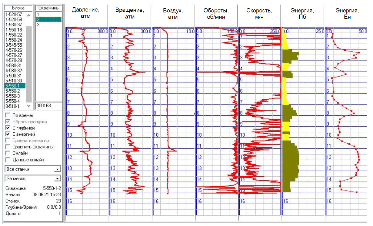
Fig.1. Blast drilling parameters provided by BlastMaker software
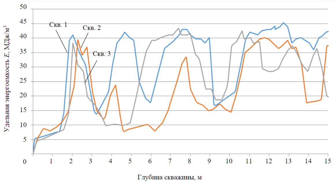
Fig.2. Dependence of specific energy consumption of roller cone drilling on block 5-550-1 on well depth
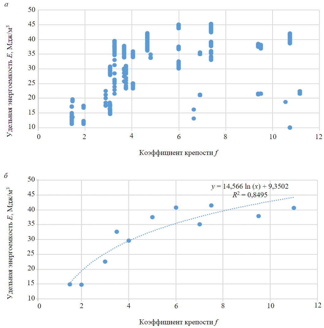
Fig.3. Distribution of drilling energy consumption values in correlation with the values of rock hardness coefficient recorded by BlastMaker (a) and after data filtration (b)
The graph (Fig.3, b) shows that the values of specific energy consumption of drilling by the roller cone method and rock hardness coefficient are approximated by a logarithmic function with a validity coefficient of 0.84:
where Е – specific drilling energy consumption in BlastMaker, MJ/m3; f – rock hardness coefficient.
Then, the hardness coefficient can be calculated as:
Data analysis revealed the following:
- rock density does not affect the parameters of roller cone drilling;
- the tension strength of the sample has an influence on the axial pressure values;
- the number of rock sample compressive shear strength values is insufficient to reveal statistically significant correlation dependencies.
Therefore, the specific energy consumption of drilling was taken as the main parameter of drilling boreholes using the roller cone method.
We tested the results on technological blocks consisting of clay rocks and limestone, according to geological exploration data. Initially, the explosive block was drilled by the roller cone drilling machines with the “Kobus” on-board controller. Then, the obtained data on drilling energy consumption were used to select the required charge design and calculate the mass of explosives in each hole. During block preparation for explosion one-half was charged using the technology approved at the enterprise.
Drilling and blasting parameters at the experimental blocks: borehole grid a x b – 6 x 7, 6 x 6, 6 x 6 m; specific consumption q – 0.58, 0.57, 0.69 kg/m3; stemming type – sand-clay mixture; initiation system – non-electric (“Iskra”).
The second part was charged in accordance with the drilling data. That is, in the boreholes where the coefficient of rock hardness was more than two, solid charges of granulite RP were made; in case of a lower hardness coefficient there were deck charges. The same construction was also implemented in the boreholes, where hardness coefficient of rocks was less than two. A sand-clay mixture was used as stemming, that kept the gaseous explosion products inside the borehole sufficiently for a long time to fully transfer the explosion energy to the walls of the blast hole [40]. At the same time, the borehole grid remained unchanged.
Figure 4 shows the plans of the experimental blocks with the areas where charging was done with the proposed method. The initiation means at the sections with standard parameters of blasting and drilling and at the experimental sections were linked into a single explosive system.
It was determined from the site examination that in the standard block sections with concentrated charges the explosion caused ejection funnels, thus indicating an excessive mass of explosives, and on the experimental sites the number and size of the funnels were smaller (Fig.5). Excavation performance at the experimental sections of blocks, according to the excavation data, was 15 to 20 % higher than at the standard ones. That indicates the relevance of the proposed approach to determine blasting and drilling parameters based on the results of specific drilling energy consumption measurement.
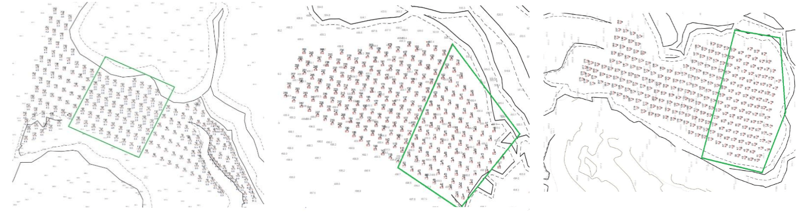
Fig.4. Location plans of drilling and blasting wells on the experimental blocks (green contour are areas where explosive charging was done according to the specific energy consumption of drilling)
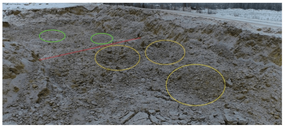
Fig.5. Results of drilling and blasting on the experimental block (yellow color indicates funnels with standard parameters, green – with experimental ones)
Results and discussion
It is essential to emphasize that the correlation between the physical and mechanical properties of rocks and drilling parameters is the only reliable way to identify rocks, since each parameter is determined directly on the samples and on the rock mass. It is worth to know that the obtained correlation dependence is valid only for the Kuranakh ore field rocks. However, the proposed method is applicable to all deposits. The application of this technique is reasonable at those deposits where physical and mechanical properties of rocks are sharply different.
The next step is to estimate the reference specific energy consumption for rock crushing by the explosion of different strength of rocks that compose the massif of the Kuranakh ore field. It will allow to achieve the optimization of energy costs and calculation of the charge mass necessary for crushing of the rock massif in this area.
Conclusion
Based on the study of national and international experience, it was found that the quality of the explosion depends on the specific energy consumption for rock crushing by explosion, which, in turn, depends on the physical and mechanical properties of rocks. Despite the charge energy distribution, achieving the necessary volumetric concentration of energy in different parts of the borehole, these methods are useful only in the mining enterprises where the massif structure is known with accurate. These include, for example, deposits with unchanging layering, and that can be identified by layer exposures on the scarp slope. At the deposits with complex geological structure, where the massif structure varies within small areas, it is not reliable to determine the structure on exposed surfaces. As a result, the calculation of drilling and blasting parameters, as a rule, is based on the hardest rocks, resulting in overconsumption of explosives and suboptimal crushing quality.
These properties are obtained at each blasted block by testing rock samples, which is a very labor-intensive and time-consuming job. However, it is known that drilling parameters – drilling speed, drilling energy, axial pressure exerted on the bottom hole, rotator power – respond to changes in these properties during rock fracture. We propose the algorithm for the task of rational energy distribution over the borehole depth depending on rock physical-mechanical properties. The correlation between the drilling parameters and these properties will make it possible to identify the block rocks. This will provide data on rock physical and mechanical properties, but it will not make it possible to determine the required amount of explosives both at the borehole depth and over the area. To achieve the task, it is essential to estimate the reference specific energy consumption for each rock type that forms the rock massif. As a result, the rock classification based on the values of drilling parameters and the specific energy consumption for crushing of these rocks makes it possible to rationally distribute the explosion energy both at the depth of the borehole and over the block area. Further, it will provide an excellent opportunity to obtain the required quality of crushing.
References
- Yastrebova K.N., Moldovan D.V., Chernobay V.I. Solving the Issue of Ventilating Atmosphere of Opencast Mining by Resloping Bench Face. International Journal of Advanced Science and Technology. 2020. Vol. 29. N 1, p. 1-6.
- Fomin S.I., Govorov A.S. Validation of the chosen cutoff grade value in open pit mine design. Mining Informational and Analytical Bulletin. 2023. N 12, p. 169-182 (in Russian). DOI: 10.25018/0236_1493_2023_12_0_169
- Kanchibotla S.S., Vizcarra T.G., Musunuri S.A.R. et al. Mine to mill optimisation at Paddington gold operations. The 6th International conference on Semi-Autogenous and High Pressure Grinding Technology, 20-24 September 2015, Vancouver, Canada. Canadian Institute of Mining and Metallurgy, 2015, p. 13.
- Saadoun A., Fredj M., Boukarm R., Hadji R. Fragmentation analysis using digital image processing and empirical model (KuzRam): a comparative study. Journal of Mining Institute. 2022. Vol. 257, p. 822-832. DOI: 10.31897/PMI.2022.84
- Bhatawdekar R.M., Edy M.T., Danial J.A. Building Information Model for Drilling and Blasting for Tropically Weathered Rock. Journal of Mines, Metals and Fuels. 2019. Vol. 67. Iss. 11, p. 494-500.
- Dolzhikov V.V., Ryadinsky D.E., Yakovlev A.A. Influence of deceleration intervals on the amplitudes of stress waves during the explosion of a system of borehole charges. Mining Informational and Analytical Bulletin. 2022. N 6-2, p. 18-32 (in Russian). DOI: 10.25018/0236_1493_2022_62_0_18
- Vinogradov Y.I., Khokhlov S.V. The drilling-and-blasting parameters determination method for specified grain-size composition of the blasted rock mass. Mining Informational and Analytical Bulletin. 2015. N S1-4, p. 20-29 (in Russian).
- Marinin M.A., Rakhmanov R.A., Dolzhikov V.V., Sushkova V.I. Study of the effect of blasted rock mass parameters on the performance of excavator-automobile complex. Mining Informational and Analytical Bulletin. 2023. N 9-1, p. 35-48 (in Russian). DOI: 10.25018/0236_1493_2023_91_0_35
- Abbaspour H., Drebenstedt C., Badroddin M., Maghaminik A. Optimized design of drilling and blasting operations in open pit mines under technical and economic uncertainties by system dynamic modelling. International Journal of Mining Science and Technology. 2018. Vol. 28. Iss. 6, p. 839-848. DOI: 10.1016/j.ijmst.2018.06.009
- Zhukovskiy Y.L., Korolev N.A., Malkova Y.M. Monitoring of grinding condition in drum mills based on resulting shafttorque. Journal of Mining Institute. 2022. Vol. 256, p. 686-700. DOI: 10.31897/PMI.2022.91
- Rasskazov M.I., Potapchuk M.I., Tsoi D.I. et al. Study of mining and geological features and definition of physical and mechanical properties of rocks of Delken gold deposits. Problems of Subsoil Use. 2020. N 2 (25), p. 116-126 (in Russian). DOI: 10.25635/2313-1586.2020.02.116
- Zharikov S.N. Correlation of specific energy characteristics of roller drilling and rock mass explosive destruction processes: Candidate’s thesis, Ekaterinburg: The Institute of Mining UrO RAN, 2011, p. 25 (in Russian).
- Kryukov G.M. Model of explosive rock loosening at pits. Boulder frequency. Average size of rock fragments in the breakdown. Moscow: Izd-vo Moskovskogo gosudarstvennogo gornogo universiteta, 2005, p. 28 (preprint) (in Russian).
- Langefors U., Kihlström B. The modern technique of rock blasting. Moscow: Nedra, 1968, p. 298.
- Salmi E.F., Sellers E.J. A review of the methods to incorporate the geological and geotechnical characteristics of rock masses in blastability assessments for selective blast design. Engineering Geology. 2021. Vol. 281. N 105970. DOI: 10.1016/j.enggeo.2020.105970
- Simioni S., Sidler R., Dual J., Schweizer J. Field measurements of snowpack response to explosive loading. Cold Regions Science and Technology. 2015. Vol. 120, p. 179-190. DOI: 10.1016/j.coldregions.2015.06.011
- Zou D. Explosives. Theory and Technology of Rock Excavation for Civil Engineering. Singapore: Springer, 2017, p. 105-170. DOI: 10.1007/978-981-10-1989-0_3
- Baron V.L., Kantor V.Kh. Blasting techniques and technology in the USA. Moscow: Nedra, 1989, p. 376 (in Russian).
- Rzhevskii V.V. Physical and technical parameters of rocks. Мoscow: Nauka, 1975, p. 212 (in Russian).
- Ugolnikov V.K., Simonov P.S. Identifying conversion factors in the calculation of equivalent crushing charges. Vestnik Magnitogorskogo gosudarstvennogo tekhnicheskogo universiteta im. G.I.Nosova. 2007. N 4 (20), p. 14-17 (in Russian).
- Zharikov S.N. The energy intensity of excavation of rock mass and the relationship of the extract with similar processes of mining operations. Journal of Fundamental and Applied Mining Sciences. 2017. Vol. 4. N 1, p. 179-186 (in Russian).
- Khomenko O.E., Kononenko M.N., Lyashenko V.I. Rationale for Technologies and Facilities for Carrying out Horizontal Mine Workings Using Emulsion Explosives. Vestnik Magnitogorskogo gosudarstvennogo tekhnicheskogo universiteta im. G.I.Nosova. 2021. Vol. 19. N 3, p. 5-15 (in Russian). DOI: 10.18503/1995-2732-2021-19-3-5-15
- Avdeev A.N., Sosnovskaia E.L., Bolotnev A.Y. Strength coefficient estimation by indirect methods. Izvestiya vysshikh uchebnykh zavedenii. Gornyi zhurnal. 2021. N 3, p. 28-35 (in Russian). DOI: 10.21440/0536-1028-2021-3-28-35
- Neobutov G.P. Drillability estimation of the Nezhdaninskoe gold deposit in Yakutia. Mezhdunarodnyi nauchno-issledovatelskii zhurnal. 2019. N 7 (85), p. 38-43. DOI: 10.23670/IRJ.2019.85.7.007
- Gospodarikov A.P., Trofimov A.V., Kirkin A.P. Evaluation of deformation characteristics of brittle rocks beyond the limit of strength in the mode of uniaxial servohydraulic loading. Journal of Mining Institute. 2022. Vol. 256, p. 539-548. DOI: 10.31897/PMI.2022.87
- Kuznetsov N.N., Pak A.K. Influence of the hard rock specimens’ size ratio on the results of their strength determination under uniaxial compression. Vestnik of MSTU. 2014. Vol. 17. N 2, p. 246-253 (in Russian).
- Korshunov V.A., Pavlovich A.A., Bazhukov A.A. Evaluation of the shear strength of rocks by cracks based on the results of testing samples with spherical indentors. Journal of Mining Institute. 2023. Vol. 262, p. 606-618. DOI: 10.31897/PMI.2023.16
- Navarro J., Seidl T., Sanchidrián J.A. et al. Blastability and Ore Grade Assessment from Drill Monitoring for Open Pit Applications. Rock Mechanics and Rock Engineering. 2021. Vol. 54. Iss. 6, p. 3209-3228. DOI: 10.1007/s00603-020-02354-2
- Navarro J., Schunnesson H., Ghosh R. et al. Application of drill-monitoring for chargeability assessment in sublevel caving. International Journal of Rock Mechanics and Mining Sciences. 2019. Vol. 119, p. 180-192. DOI: 10.1016/j.ijrmms.2019.03.026
- Rai P., Schunnesson H., Lindqvist P.-A., Kumar U. Measurement-while-drilling technique and its scope in design and prediction of rock blasting. International Journal of Mining Science and Technology. 2016. Vol. 26. Iss. 4, p. 711-719. DOI: 10.1016/j.ijmst.2016.05.025
- Khorzoughi M.B., Hall R., Apel D. Rock fracture density characterization using measurement while drilling (MWD) techniques. International Journal of Mining Science and Technology. 2018. Vol. 28. Iss. 6, p. 859-864. DOI: 10.1016/j.ijmst.2018.01.001
- Teale R. The concept of specific energy in rock drilling. International Journal of Rock Mechanics and Mining Sciences & Geomechanics Abstracts. 1965. Vol. 2. Iss. 1, p. 57-73. DOI: 10.1016/0148-9062(65)90022-7
- Schunnesson H. RQD predictions based on drill performance parameters. Tunnelling and Underground Space Technology. 1996. Vol. 11. Iss. 3, p. 345-351. DOI: 10.1016/0886-7798(96)00024-7
- van Eldert J., Schunnesson H., Johansson D. et al. Application of Measurement While Drilling Technology to Predict Rock Mass Quality and Rock Support for Tunnelling. Rock Mechanics and Rock Engineering. 2020. Vol. 53. Iss. 3, p. 1349-1358. DOI: 10.1007/s00603-019-01979-2
- Dolgiy I.E., Nikolaev N.I. Resistance of rocks to crushing during well drilling. Journal of Mining Institute. 2016. Vol. 221, р. 655-660. DOI: 10.18454/PMI.2016.5.655
- Tangaev I.A. Energy consumption of extraction and refining processes. Moscow: Nedra, 1986, p. 231 (in Russian).
- Ignatiev S.A., Sudarikov A.E., Imashev A.Z. Modern Mathematical Forecast Methods of Maintenance and Support Conditions for Mining Tunnels. Journal of Mining Institute. 2019. Vol. 238, p. 371-375. DOI: 10.31897/PMI.2019.4.371
- Koteleva N.I., Valnev V.V., Korolev N.. Augmented reality as a means of metallurgical equipment servicing. Tsvetnye metally. 2023. N 4, p. 14-23 (in Russian). DOI: 10.17580/tsm.2023.04.02
- Klyuchnikov N., Zaytsev A., Gruzdev A. et al. Data-driven model for the identification of the rock type at a drilling bit. Journal of Petroleum Science and Engineering. 2019. Vol. 178, p. 506-516. DOI: 10.1016/j.petrol.2019.03.041
- Moldovan D.V., Chernobay V.I., Sokolov S.T., Bazhenova A.V. Design concepts for explosion products locking in chamber. Mining Informational and Analytical Bulletin. 2022. N 6-2, p. 5-17 (in Russian). DOI: 10.25018/0236_1493_2022_62_0_5