Analysis of the assessment of the prospects for the burial of CO2 in unexplored aquifer complexes on the example of a facility in the Perm Region
- 1 — Ph.D. Associate Professor Nazarbayev University ▪ Orcid
- 2 — Ph.D. Director of the Scientific and Educational Center Perm National Research Polytechnic University ▪ Orcid
- 3 — First Deputy Director LLC SIE “PrognozRNM” ▪ Orcid
- 4 — Leading Engineer National Research Polytechnic University ▪ Orcid
- 5 — Project Manager Perm World-class Scientific and Educational Center “Rational Subsoil Use” ▪ Orcid
- 6 — Chief Specialist Gazprom Neft Company Group ▪ Orcid
Abstract
One of the most important problems of our time is the annual increase in greenhouse gas emissions into the atmosphere. It is possible to combat this phenomenon by reducing emissions or developing and applying technologies for capturing, storing, using and disposing of CO2. In this work, an assessment of the expediency and possibility of carbon dioxide burial in deep aquifers is considered, the study of which is carried out to a small extent and due to the lack of useful material in them. The parameters and results of CO2 injection into the aquifer of one of the oil fields of the Perm Region, the geological properties and characteristics of which are determined in this work, are studied. The criteria of applicability, methods of estimating the volume of the reservoir and laboratory studies to determine the properties of CO2 and the features of its interaction with the model of the reservoir fluid are considered. The injection object and reservoir volume were determined, PVT studies of the target gas were performed, and its solubility in reservoir water was determined. The duration of filling the full volume of the trap when capturing 400 thousand tons of CO2 per year from the target industrial facility is calculated to be 202 years. This conclusion signals the prospects for the burial of carbon dioxide in the underground deposits of an undeveloped aquifer complex in the Perm Region, which reflects the importance of studying such geological CO2 burial sites in order to achieve global carbon neutrality goals.
The research was carried out with the financial support of the Strategic Academic Leadership Program “Priority 2030”.
Introduction
An important problem that has received significant publicity in the last decade is the increase in the average temperature on the planet due to the emission of greenhouse gases into the atmosphere [1]. At the same time, carbon dioxide is the main greenhouse gas (more than 70 % of global emissions). Currently, there are no signs of a reduction in greenhouse gas emissions [2, 3]. At the same time, the potential growth of industrial production in developing countries, the slow transition to renewable sources and energy crises suggest an increase in these emissions in the coming years [4]. There are two ways to combat global warming – minimizing the number of sources of emissions or developing CO2 capture technologies. The use of CO2 capture and storage methods can play a crucial role in preventing global warming [5]. A detailed analysis of existing technologies is carried out in [6, 7].
Carbon emission reduction technologies can be divided into four categories – capture, storage, application, and disposal. CO2 capture technologies are quite advanced and are represented by chemical absorption or various membrane technologies [8-10]. CO2 transport technologies are also developed and used in industry, with more than 6,500 km of pipelines worldwide [11, 12]. CO2 storage technologies are known all over the world, currently there are a large number of existing projects for the disposal of carbon dioxide. According to the works [13, 14], the utilization of this gas is also actively used in various industries. In particular, these technologies can be found in the food, construction, and chemical industries [15, 16]. CO2 also finds useful applications [17, 18] as a component in the composition of a product. Scientific publications [19, 20] report on the use of CO2 in industry, for example, in the production of various materials, chemicals and as an agent for increasing oil recovery (IOR). Due to the global trend towards reducing CO2 emissions, new projects involving the burial of gas in various aggregate states and in different facilities are being prepared. In this paper, an evolving method of CO2 disposal is considered – disposal into depleted mining facilities, salt formations, coal deposits or aquifers [21-23].
The disadvantages of CO2 burial in coal seams are the low efficiency of methane storage, insufficient knowledge of the interaction of methane and CO2 under the conditions under consideration, and imperfection of the technology [24-26]. Injection into saline and saline aquifers is the most preferable, since it can be used in industrial, agricultural and other applications [27]. These horizons have the greatest ability to sequester CO2 [28, 29]. A brief analysis of the world experience in CO2 burial, given in [30-32], is presented to determine the most optimal characteristics of reservoir formations. Basically, this experience is presented in foreign markets, since foreign countries addressed the issue of carbon dioxide utilization much earlier [33-35]. Based on the results of the performed assessment and on the basis of the work [36], it was concluded that the cost of implementing CO2 storage technologies in depleted oil deposits and in deep salt formations is similar, while storage in gas deposits can cost much more. Injection into oil fields for IOR and increased extraction of coal methane CO2 has a positive effect and can make burial more economically attractive, however, in this case, many factors must be taken into account (technology efficiency, oil/methane prices, etc.). At the same time, the main costs in the implementation of most technologies, with the exception of burial in coal reservoirs, are capital expenditures for injection equipment [37].
A comprehensive work is presented to substantiate the choice of an object for CO2 injection, the properties of the collector are determined, laboratory studies are performed to determine the pressure-volume-temperature (PVT) properties of the target gas, as well as its dissolution coefficient in the reservoir fluid and to determine the volume of injection of the target gas into the studied deposit.
Methods
Geological requirements for reservoirs for efficient CO2 disposal
A review of global CO2 storage projects shows that the rock must have high porosity, be permeable to carbon dioxide; the reservoir must be covered with impermeable rocks, located at a depth at which the gas is under pressure corresponding to liquid or supercritical conditions, and be composed of rocks that do not react with CO2 in the presence of water (sandstone, mudstone, siltstone, etc.). The availability of infrastructure and communications in the region is also an indispensable criterion. Criteria for selecting an object:
- collector horizons should have caps stacked with impermeable plastic or hard rocks above them;
- the cap above the selected object must be sustained in the area of distribution, its capacity must be at least 2-6 m at a depth of up to 600 m and 4-5 m at a depth of more than 600 m;
- the depth of the collector must ensure that CO2 is in supercritical or liquid states;
- in order to ensure the long-term operation of storage facilities, additional interlayers with sealing ability must be identified in the section;
- there should be no tectonic disturbances within the design contour of the future CO2 storage, causing a decrease in the tightness of the main and backup caps;
- the permeability of the cap to carbon dioxide should not exceed 7-10 mm2.
The results of the research have shown that for CO2 storage facilities at elevated pressure, the depth of its deposition is of great importance. To prevent gas leaks through cracks, the hydrostatic pressure of groundwater along the storage contour must exceed the internal gas pressure. Large granitoid massifs are recognized as the best in terms of stability of underground structures. In the practice of selecting locations for underground gas storage facilities, great importance is attached to the search for monolithic structural blocks in geological formations.
In [38], the properties of CO2 were studied under various conditions and it was determined that the depth of the reservoir for its injection should be more than 1000 m, since at this mark the injected CO2 will be in a supercritical state.
Selection of the research object and quantitative assessment of the reservoir volume
Based on certain criteria and analysis of oil field development facilities, an aquifer complex of one of the oil fields in the south of the Perm Region, in particular, the Famensk deposits, was selected for CO2 storage.
An expert assessment of the volume of the reservoir, which theoretically can accommodate the injected carbon dioxide, was carried out on the basis of the formula for calculating reserves by the volumetric method, excluding variables responsible for saturation:
where S – collector distribution area, m2; heff – effective thickness of the reservoir, m; kp – porosity coefficient, fraction units.
To calculate the area of the formation under consideration, a structural map of the roof of its surface was created, based on a map based on the reflecting horizon IIk (roof of Visean terrigenous deposits) using the convergence method in the Surfer and CorelDraw software product. Using well breakdowns, the thickness values from the known surface along the roof of the Tula terrigenous horizon to the roof of the Famensk deposits were determined. The Isochore map is based on these data. Combining the structural map according to IIk with the isochore map, when they intersect, it is possible to determine the absolute mark of the required surface – the roof of the Famen deposits at many points on the map, the calculation is performed according to the rules of algebraic summation. As a result, a structural map of the roof of the Famen deposits was obtained.
The area is calculated within the last closed isohypse lying inside the boundaries of the license area. A closed stratoisogypse with an absolute mark of 1,420 m was selected. Within this isohypse, the area is calculated using the GetCurve macro in the CorelDraw software. As a result, the area of the selected site is 102.2 km2. Famensk oil deposits are distributed in the south of the Perm Region and are confined to the southeastern side of the Kamsko-Kinel system of deflections. The effective thickness and porosity were determined based on the analysis of the field experience of exploitation of these Famen deposits. The data set for thickness was 107 values, and for porosity – 3,991. Based on the obtained values, histograms are constructed, the boundaries of the values are determined and a statistical analysis is carried out. For the best prediction of the determined indicator, the built-in analysis packages in the Excel software product are used. Using the TRIANG_INV function, where limits are set in the form of minimum, maximum, and modal values, 10 thousand random variables (for representativeness) are modeled according to the porosity coefficient and effective thickness, the reservoir propagation area remains unchanged. According to the formula for estimating the reservoir volume, 10 thousand values were obtained.
Physico-chemical properties of the studied sample of water and carbon dioxide
To implement PVT research, a model of gas coming from the short-cycle adsorption unit (SCA) of one of the industrial facilities of the Perm Region has been artificially created. This gas is a mixture of two gases – carbon dioxide (93 %) and methane (7 %). The density of the studied water under normal conditions is 1,180 kg/m3, viscosity is 1.55 mPa s, mineralization is 256.6 g/l. Since sampling from an undeveloped object is not possible, the sample was taken from an overlying object. According to the project document for the development of the field in question, the properties of reservoir water at these facilities differ slightly and do not make any changes to the results of laboratory experiments.
Laboratory tests on a PVT installation
The following equipment was used in the research: AMCore AMR-F 1004.01 thermodynamic research unit, AMCore AMR-T 1000.15 sample recombination unit, AMCore AMR-F 1002 automatic gasometer, Anton Paar GmbH liquid density analyzer, AMCore AMR-AMP200 automatic measuring press, AERUS 210/24 air piston coaxial compressor, low-temperature liquid thermostat KRIO-VT-12-1 series MASTER of LLC “TERMEX”.
The main stages of research:
- estimation of the phase state of the target gas under various pressure conditions;
- analysis of the density of the target gas under various pressure conditions;
- determination of the compressibility coefficient of the target gas under various pressure conditions;
- estimation of the dissolution coefficient of the target gas in reservoir water under various pressure conditions.
The analysis of the phase state of the target gas consisted in obtaining the P-V dependence for the test sample with the release of a critical pressure corresponding to the transition of the gas from a liquid state to a mixed one (liquid + gas). In other words, at a given pressure, the first bubble of gas is released from the liquid. The temperature of the performed studies in all cases is 28 °С, which corresponds to the thermal conditions of the studied formation. The density of the mixture was also determined to represent its physical properties in reservoir conditions. Taking into account these values of gas density under various pressure conditions, the compressibility coefficients of the studied mixture are calculated:
where ρ – the density of the target gas at pressure P (MPa) and temperature T (K) modeled in a PVT cell, kg/m3; ρ0 – the density of the target gas under standard conditions (P0 = 0.101325 MPa, T0 = 293.15 K), assumed to be 1.983 kg/m3.
The estimation of the gas dissolution coefficient in reservoir water plays an important role in determining the possible volume of CO2 burial in connection with the known fact of gas dissolution in reservoir waters, as a result of which it is necessary to estimate the volume of the studied gas capable of dissolving in water that saturates the target formation. To do this, a series of studies was carried out on a PVT installation, into which a certain amount of a gas mixture and a 4.6 ml water sample were pumped using auxiliary laboratory equipment.
Assessment of the possible volume of injection of the target gas into the studied deposit
Based on the calculations of the volume of the deposit and the properties of the target gas, it was necessary to calculate the volume of gas that the deposit in question can accommodate. To do this, it was necessary to determine the maximum pressure that can be created in the reservoir, based on an estimate of the hydraulic fracturing pressure and the maximum pressure limited by the technological equipment. The injection volume is defined as the ratio of CO2 emissions to the calculated reservoir volume.
Determination of the maximum pressure in the target deposit
According to the analysis of the technical characteristics of the existing technological equipment, the maximum pressure is about 35 MPa. When estimating hydraulic fracturing pressure, a calculation scheme using the Hubbert – Willis formula was used:
where Prock – rock pressure, Prock = ρrockgHres, MPa; ρrock – rock density, kg/m3; g – acceleration of free fall, g = 9,81 m/s2; Hres – reservoir depth, m; Pres – reservoir pressure, Pres = rwgHres, MPa; ρw – water density, kg/m3.
Discussion of the results
The estimation of the reservoir volume was performed according to the described method. As a result of statistical analysis using percentiles, the following results were obtained:
- The 10th percentile means that only 10 % of the sample collector volume takes values less than or equal to 103,177.6 thousand m3;
- The 50th percentile – it is equally likely that the volume of the collector can take values both less and more than 269,216.9 thousandm3;
- The 90th percentile – only 10 % of the sample collector volume takes values greater than and equal to 591,583.8 thousand m3.
The authors of the work for further research adopted the volume according to the worst case scenario, i.e. 10 percentile – 103,177.6 thousand m3.
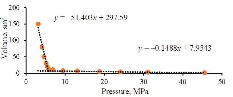
Fig.1. P-V dependence of the target gas
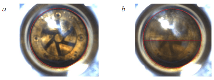
Fig.2. Cells filled with the target gas at different pressures: P = 45.51 MPa (a); P = 5.12 MPa (b)
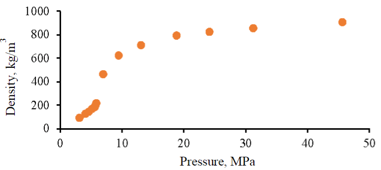
Fig.3. Dependence of the target gas density on the pressure created in the PVT unit cell
Studies of PVT properties of the target gas
Based on the results of the interpretation of the P-V dependence of the target gas (Fig.1), it was determined that the critical pressure of the transition from a liquid state to a mixed one corresponds to a value of 5.59 MPa. Images of a cell filled with a target gas are presented. At a pressure of 45.51 MPa, the target gas is completely in the liquid phase (Fig.2, a) and a phase boundary is observed at 5.12 MPa (Fig.2, b). The obtained critical pressure is confirmed by visual analysis.
The result of the measurement of the density of the mixture performed in this study is shown in Fig.3. Based on the results of the density assessment, the values of the compressibility coefficient are calculated according to the formula (2). When the pressure increases to a critical value, the compressibility coefficient decreases from 0.64 to 0.51, after which it decreases to 0.28 at a pressure of 6.9 MPa. With a further increase in pressure, this parameter increases to 0.29 at a pressure of 9.4 MPa, 0.35 at 13.0 MPa, 0.56 at 24.1 MPa and 0.96 at 45.51 MPa. The value of the results obtained lies in the possibility of increasing the accuracy of estimating the numerical values of gas injection volumes from the SCA block to the target object.
The results of the study of the dissolution coefficient of the target gas in reservoir water are shown in Fig.4. The interface between the phases of the target gas and water is clearly visible in the image of a PVT cell filled with a mixture of the target gas and reservoir water at a pressure of 39.12 MPa (Fig.5).
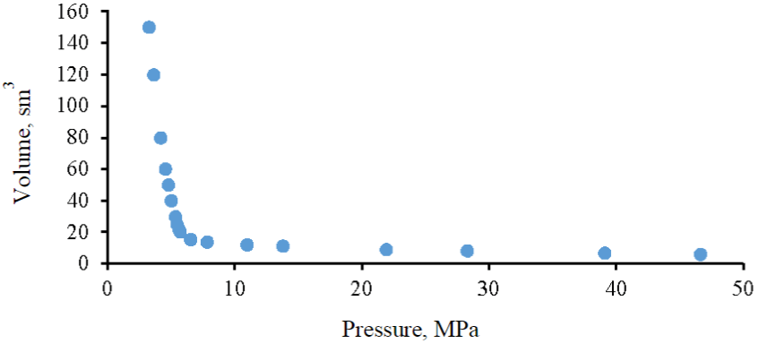
Fig.4. P-V dependence of the mixture of the target gas and water
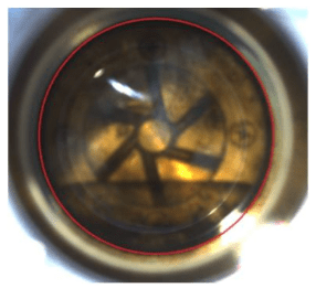
Fig.5. A cell filled with a mixture of target gas and reservoir water at P = 39.12 MPa
To estimate the coefficient of dissolution of the target gas in reservoir water, a combined graph of P-V dependencies was constructed, and a graph of the P-V dependence of the mixture of target gas and reservoir water minus the volume of this water was added, which allows, when analyzing graphs, to estimate the dissolved volume of gas in water under various baric conditions (Fig.6). The superimposition of red (a mixture of gases) and green (a mixture of gases and water (minus the volume of water) lines indicates that the process of dissolving the target gas in reservoir water is absent in the entire range of considered baric conditions at reservoir temperature, therefore, when estimating the volume of gas injection from the SCA block into the Famensk deposits, it must be taken into account that the entire volume of injected gas will be in a free state under reservoir conditions.
The experience of CO2 burial [31, 34, 35] also indicates the low solubility of this gas in reservoir water. In [39-41], laboratory studies of the effect of various factors on the solubility of CO2 in water were carried out, which showed a decrease in solubility with an increase in water mineralization. Moreover, the solubility of CO2 increases significantly with an increase in the temperature of the study. Based on this analysis, it can be concluded that the research is correct.
Determination of the volume of injection of the target gas into the studied deposit
It is assumed that the entire volume of the Famensk deposit will be occupied by this gas, and the reservoir water is displaced beyond the established volume of the trap within the license area. This assumption is justified by the laws of gravitational phase separation due to the lower density of the target gas in the considered pressure range.
The analysis of hydraulic fracturing pressures at the Famensk deposits of the Perm Region, as well as according to equation (2), showed that the hydraulic fracturing pressure corresponds to a value of 23 MPa, which is less than the maximum allowable pressure of the technological equipment used. As a result, when estimating the volume of injection of the target gas into the deposit under consideration, it is necessary to limit the pressure of hydraulic fracturing with a margin of 20 %, i.e. the calculation of the volumes of the target gas was carried out at a critical pressure of 18.4 MPa. To determine the mass of the injected volume of the target gas into the reservoir, an extrapolation of the graph of the dependence of the density of the target gas on pressure was performed (see Fig.3). It was determined that at an approved critical pressure of 18.4 MPa, the density of the gas mixture under study will be 784.6 kg/m3, while the gas must be in a liquid state.
Taking into account the volume of the Famensk deposit, the mass of the target gas has been determined, which is able to fit into this deposit according to the results of the implemented studies – gas injection from the SCA block can last for 202 years (assuming a gas consumption of 400 thousand tons per year) and will eventually amount to 80.95 million t.
Economic assessment of the project
The economic model of the proposed project involves assistance from the state in the form of subsidies. This is due to the high cost at which the accumulated discounted net cash flow (CDCF) is negative at the end of the estimated period. The model contains all the costs of capital investments (construction of a carbon dioxide pipeline, well construction, necessary equipment) and operating costs to ensure the operation of the system. One of the important items of expenditure is the necessary complex of works on the additional study of deposits and fluids for the final justification of the possibility and expediency of the project. Large fines for carbon dioxide emissions into the atmosphere are included in the profit column.
Economic calculations, according to which the payback period of the project was adopted, equal to 15 years, showed that with a state subsidy of 24.6 rub. per ton of recycled gas, the project reaches a positive CDCF. According to the authors, this model reflects a realistic version of the project. With an increase in the accepted payback period, subsidies decrease.
Assessment of risks and environmental impacts in the implementation of CO2 disposal technology
Mechanisms contributing to the re-release of carbon dioxide to the surface [42, 43]:
- migration of gas in separate parts through disturbed and permeable rocks, as well as through injection wells (corrosion, wear);
- molecular diffusion and dissolution of carbon dioxide through the covering rocks;
- movement of CO2 along with moving aquifers;
- man-made land disturbance, mining dumps, tailings ponds, contributing to the disturbance of the underground geological space and an increase in CO2 leaks.
It is noted in [44] that pumping large volumes of carbon dioxide into underground storage facilities can lead to earthquakes, collapse of the storage facility and subsequent emissions into the atmosphere. The risks associated with leakage as a result of CO2 storage in geological reservoirs are divided into global and local. Risks at the global level are associated with CO2 emissions, which can significantly contribute to climate change if a certain proportion of gas leaks into the atmosphere [45]. Local-level risks can be classified as risks to health, safety and the environment – leakage of CO2 into the atmosphere or shallow Earth layers, intensification of chemical processes due to the ingress of dissolved CO2 into the subsurface and effects arising from the displacement of liquids by injected CO2 [46, 47]. The classic ways to reduce the danger associated with these types of leaks are careful design and selection of a storage system location, as well as the use of early leak detection methods (preferably long before CO2 reaches the earth's surface) [48-50].
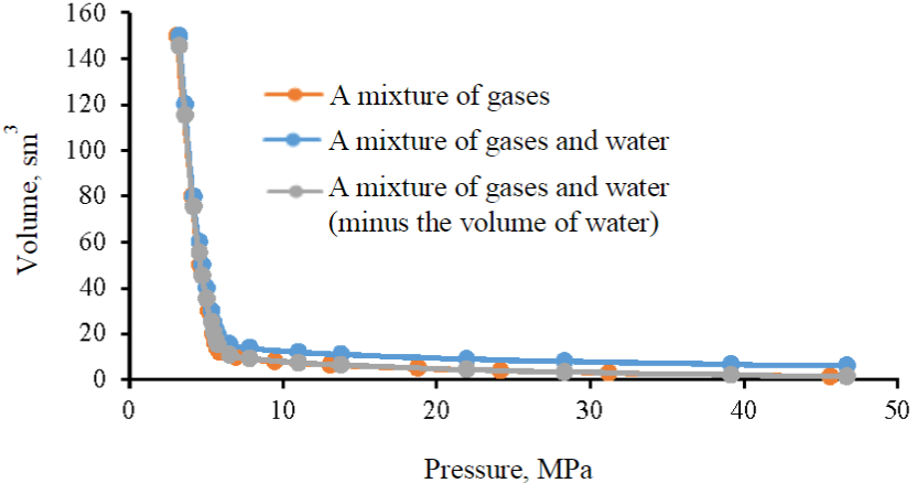
Fig.6. P-V dependencies of the target gas, a mixture of the target gas and reservoir water
Conclusion
The development and practical application of CO2 disposal technologies is one of the most important areas in the fight against global warming. The proposed technology for using carbon dioxide can become the main one in solving the problem of CO2 emissions both at the considered enterprise and in Russia as a whole.
The criteria for selecting an object for the implementation of carbon dioxide burial technology in geological reservoirs are determined. Taking into account the geological structure, the optimal target object was determined on the territory of the Perm Region, the volume of the deposit was estimated, which with a probability of 90 % will be at least 103177.6 thousand m3.
Laboratory studies were performed, according to the results of which the PVT properties of the target gas, its density and compressibility coefficient under various barometric conditions, as well as solubility in reservoir water were determined. The results obtained show that the entire volume of the injected gas will be in a free state under reservoir conditions, and not partially dissolved.
The assessment of the injection parameters and calculations showed that when 400 thousand t of CO2 are captured from an industrial facility per year, injection until the reservoir volume is fully filled can last for 202 years, and will amount to 80.95 million t of this gas.
The creation of an economic model allows us to approve the payback of the proposed project over a fifteen-year period with the support of the state (for the disposal of CO2 emissions into the Earth's atmosphere) in the amount of 24.6 rub./t.
The significant environmental effect of carbon dioxide burials in the underground sediments of an undeveloped aquifer complex indicates the need to draw attention to these objects, which are currently little or not studied at all due to the lack of industrial significance.
As recommendations for further study of the host structure (determining the boundaries of the deposit, its structure and characteristics), as well as the processes occurring in the reservoir, it is proposed to conduct field and geophysical studies of existing wells and drilling new ones; laboratory studies, including PVT studies and filtration.
References
- Ilinova А.А., Romasheva N.V., Stroykov G.A. Prospects and social effects of carbon dioxide sequestration and utilization projects. Journal of Mining Institute. 2020. Vol. 244, p. 493-502. DOI: 10.31897/PMI.2020.4.12
- Le Quéré C., Korsbakken J.I., Wilson C. et al. Drivers of declining CO2 emissions in 18 developed economies. Nature Climate Change. 2019. Vol. 9, p. 213-217. DOI: 10.1038/s41558-019-0419-7
- Fawad M., Mondol N.H. Monitoring geological storage of CO2: a new approach. Scientific Reports. 2021. Vol. 11. N 5942. DOI: 10.1038/s41598-021-85346-8
- Quarton C.J., Samsatli S. The value of hydrogen and carbon capture, storage and utilisation in decarbonising energy: Insights from integrated value chain optimisation. Applied Energy. 2020. Vol. 257. N 113936. DOI: 10.1016/j.apenergy.2019.113936
- Rosa L., Sanchez D.L., Realmonte G. et al. The water footprint of carbon capture and storage technologies. Renewable and Sustainable Energy Reviews. 2021. Vol. 138. N 110511. DOI: 10.1016/j.rser.2020.110511
- Bui M., Adjiman C.S., Bardow A. et al. Carbon capture and storage (CCS): the way forward. Energy & Environmental Science. 2018. Vol. 11. Iss. 5, p. 1062-1176. DOI: 10.1039/C7EE02342A
- Gür T.M. Carbon Dioxide Emissions, Capture, Storage and Utilization: Review of Materials, Processes and Technologies. Progress in Energy and Combustion Science. 2022. Vol. 89. N 100965. DOI: 10.1016/j.pecs.2021.100965
- Fedoseev S.V., Tcvetkov P.S. Key Factors of Public Perception of Carbon Dioxide Capture and Storage Projects. Journal of Mining Institute. 2019. Vol. 237, p. 361-368. DOI: 10.31897/PMI.2019.3.361
- Shirinkina E.S., Sliusar N.N., Korotaev V.N. CO2 Capturing from Stationary Sources with Following Use for Enhanced Oil Recovery: A Review Of Recent Technologies. Ecology and Industry of Russia. 2021. Vol. 25. N 10, p. 64-71 (in Russian). DOI: 10.18412/1816-0395-2021-10-64-71
- Chunfeng Song, Qingling Liu, Na Ji et al. Alternative pathways for efficient CO2 capture by hybrid processes – A review. Renewable and Sustainable Energy Reviews. 2018. Vol. 82. Part 1, p. 215-231. DOI: 10.1016/j.rser.2017.09.040
- Al Baroudi H., Awoyomi A., Patchigolla K. et al. A review of large-scale CO2 shipping and marine emissions management for carbon capture, utilisation and storage. Applied Energy. 2021. Vol. 287. N 116510. DOI: 10.1016/j.apenergy.2021.116510
- Wei Lu, Hao Hu, Guansheng Qi. Effect of Pipe Diameter and Inlet Parameters on Liquid CO2 Flow in Transportation by Pipeline with Large Height Difference. Processes. 2019. Vol. 7. Iss. 10. N 756. DOI: 10.3390/pr7100756
- Ravikumar D., Duo Zhang, Keoleian G. et al. Carbon dioxide utilization in concrete curing or mixing might not produce a net climate benefit. Nature Communications. 2021. Vol. 12. N 855. DOI: 10.1038/s41467-021-21148-w
- Qian Zhu. Developments on CO2-utilization technologies. Clean Energy. 2019. Vol. 3. N 2, p. 85-100. DOI: 10.1093/ce/zkz008
- Alper E., Orhan O.Y. CO2 utilization: Developments in conversion processes. Petroleum. 2017. Vol. 3. Iss. 1, p. 109-126. DOI: 10.1016/j.petlm.2016.11.003
- Medrano-García J.D., Javaloyes-Antón J., Vázquez D. et al. Alternative carbon dioxide utilization in dimethyl carbonate synthesis and comparison with current technologies. Journal of CO2 Utilization. 2021. Vol. 45. N 101436. DOI: 10.1016/j.jcou.2021.101436
- Beheshti E., Riahi S., Riazi M. Impacts of oil components on the stability of aqueous bulk CO2 foams: An experimental study. Colloids and Surfaces A: Physicochemical and Engineering Aspects. 2022. Vol. 648. N 129328. DOI: 10.1016/j.colsurfa.2022.129328
- Farajzadeh R., Eftekhari A.A., Dafnomilis G. et al. On the sustainability of CO2 storage through CO2 – Enhanced oil recovery. Applied Energy. 2020. Vol. 261. N 114467. DOI: 10.1016/j.apenergy.2019.114467
- Bommareddy R.R., Yanming Wang, Pearcy N. et al. A Sustainable Chemicals Manufacturing Paradigm Using CO2 and Renewable H2. iScience. 2020. Vol. 23. Iss. 6. N 101218. DOI: 10.1016/j.isci.2020.101218
- Von Witzendorff P., Pohl L., Suttmann O. et al. Additive manufacturing of glass: CO2-Laser glass deposition printing. Procedia CIRP. 2018. Vol. 74, p. 272-275. DOI: 10.1016/j.procir.2018.08.109
- Ajayi T., Gomes J.S., Bera A. A review of CO2 storage in geological formations emphasizing modeling, monitoring and capacity estimation approaches. Petroleum Science. 2019. Vol. 16. Iss. 5, p. 1028-1063. DOI: 10.1007/s12182-019-0340-8
- Kelemen P., Benson S.M., Pilorgé H. et al. An Overview of the Status and Challenges of CO2 Storage in Minerals and Geological Formations. Frontiers in Climate. 2019. Vol. 1. N 9. DOI: 10.3389/fclim.2019.00009
- Dorokhin V.G. The method of using carbon dioxide in various aggregate states in underground storage of gas: Avtoref. dis. … kand. tekhn. nauk. Мoscow: Nauchno-issledovatelskii institut prirodnykh gazov i gazovykh tekhnologii, 2017, p. 26 (in Russian).
- Liangliang Jiang, Zhangxin Chen, Farouq Ali S.M. Feasibility of carbon dioxide storage in post-burn underground coal gasification cavities. Applied Energy. 2019. Vol. 252. N 113479. DOI: 10.1016/j.apenergy.2019.113479
- Kai Wang, Jienan Pan, Enying Wang et al. Potential impact of CO2 injection into coal matrix in molecular terms. Chemical Engineering Journal. 2020. Vol. 401. N 126071. DOI: 10.1016/j.cej.2020.126071
- Yang Bai, Hai-Fei Lin, Shu-Gang Li et al. Molecular simulation of N2 and CO2 injection into a coal model containing adsorbed methane at different temperatures. Energy. 2021. Vol. 219. N 119686. DOI: 10.1016/j.energy.2020.119686
- Aydin G., Karakurt I., Aydiner K. Evaluation of geologic storage options of CO2: Applicability, cost, storage capacity and safety. Energy Policy. 2010. Vol. 38. Iss. 9, p. 5072-5080. DOI: 10.1016/j.enpol.2010.04.035
- Babarinde O., Schwartz B., Jingyao Meng et al. An overview of geological carbon sequestration and its geomechanical aspects. Geological Society, London, Special Publications. 2023. Vol. 528, p. 61-72. DOI: 10.1144/SP528-2022-51
- Khan S.A. The analysis of world projects on catching and a burial place of carbonic gas. Georesources. 2010. N 4 (36), p. 55-62 (in Russian).
- Estublier A., Fornel A., Brosse É. et al. Simulation of a Potential CO2 Storage in the West Paris Basin: Site Characterization and Assessment of the Long-Term Hydrodynamical and Geochemical Impacts Induced by the CO2 Injection. Oil & Gas Science and Technology – Revue d’IFP Energies nouvelles. 2017. Vol. 72. Iss. 4. Т 22. DOI: 10.2516/ogst/2017021
- Bonto M., Welch M.J., Lüthje M. et al. Challenges and enablers for large-scale CO2 storage in chalk formations. Earth-Science Reviews. 2021. Vol. 222. N 103826. DOI: 10.1016/j.earscirev.2021.103826
- Tasianas A., Koukouzas N. CO2 Storage Capacity Estimate in the Lithology of the Mesohellenic Trough, Greece. Energy Procedia. 2016. Vol. 86, p. 334-341. DOI: 10.1016/j.egypro.2016.01.034
- Shogenov K., Shogenova A., Gei D., Forlin E. Synergy of CO2 Storage and Oil Recovery in Different Geological Formations: Case Study in the Baltic Sea. Energy Procedia. 2017. Vol. 114, p. 7047-7054. DOI: 10.1016/j.egypro.2017.03.1846
- Sliaupa S., Shogenova A., Shogenov K. et al. Industrial carbon dioxide emissions and potential geological sinks in the Baltic states. Oil Shale. 2008. Vol. 25. N 4, p. 465-484. DOI: 10.3176/oil.2008.4.06
- Verdon J.P., Stork A.L., Bissell R.C. et al. Simulation of seismic events induced by CO2 injection at In Salah, Algeria. Earth and Planetary Science Letters. 2015. Vol. 426, p. 118-129. DOI: 10.1016/j.epsl.2015.06.029
- Toth F.L., Miketa A. The Costs of the Geological Disposal of Carbon Dioxide and Radioactive Waste. Geological Disposal of Carbon Dioxide and Radioactive Waste: A Comparative Assessment. Dordrecht: Springer, 2011, p. 215-262. DOI: 10.1007/978-90-481-8712-6_8
- Heddle G., Herzog H., Klett M. The Economics of CO2 Storage. Cambridge: Massachusetts Institute of Technology, Laboratory for Energy and the Environment, 2003, p. 115.
- Khan S.A., Dorokhin V.G., Bondarenko N.P. How carbon dioxide aggregate state aspects serve to partially replace gas storage buffer volume. Gazovaya promyshlennost. 2016. N. 4, p. 50-54 (in Russian).
- Esene C., Rezaei N., Aborig A., Zendehboudi S. Comprehensive review of carbonated water injection for enhanced oil recovery. Fuel. 2019. Vol. 237, p. 1086-1107. DOI: 10.1016/j.fuel.2018.08.106
- Thomas C., Dehaeck S., De Wit A. Convective dissolution of CO2 in water and salt solutions. International Journal of Greenhouse Gas Control. 2018. Vol. 72, p. 105-116. DOI: 10.1016/j.ijggc.2018.01.019
- Guodong Cui, Yi Wang, Zhenhua Rui et al. Assessing the combined influence of fluid-rock interactions on reservoir properties and injectivity during CO2 storage in saline aquifers. Energy. 2018. Vol. 155, p. 281-296. DOI: 10.1016/j.energy.2018.05.024
- Hang Deng, Bielicki J.M., Oppenheimer M. et al. Leakage risks of geologic CO2 storage and the impacts on the global energy system and climate change mitigation. Climatic Change. 2017. Vol. 144. Iss. 2, p. 151-163. DOI: 10.1007/s10584-017-2035-8
- Pla C., Cuezva S., Martinez-Martinez J. et al. Role of soil pore structure in water infiltration and CO2 exchange between the atmosphere and underground air in the vadose zone: A combined laboratory and field approach. Catena. 2017. Vol. 149. Part 1, p. 402-416. DOI: 10.1016/j.catena.2016.10.018
- Lan-Cui Liu, Qi Li, Jiu-Tian Zhang, Dong Cao. Toward a framework of environmental risk management for CO2 geological storage in china: gaps and suggestions for future regulations. Mitigation and Adaptation Strategies for Global Change. 2016. Vol. 21. Iss. 2, p. 191-207. DOI: 10.1007/s11027-014-9589-9
- Pawar R.J., Bromhal G.S., Carey J.W. et al. Recent advances in risk assessment and risk management of geologic CO2 storage. International Journal of Greenhouse Gas Control. 2015. Vol. 40, p. 292-311. DOI: 10.1016/j.ijggc.2015.06.014
- Qi Li, Guizhen Liu. Risk Assessment of the Geological Storage of CO2: A Review. Geologic Carbon Sequestration. Cham: Springer, 2016, p. 249-284. DOI: 10.1007/978-3-319-27019-7_13
- Arora V., Saran R.K., Kumar R., Yadav S. Separation and sequestration of CO2 in geological formations. Materials Science for Energy Technologies. 2019. Vol. 2. Iss. 3, p. 647-656. DOI: 10.1016/j.mset.2019.08.006
- Hladik V., Prochac R., Opletal V. et al. CO2-SPICER – Czech-Norwegian Project to prepare a CO2 storage pilot in a carbonate reservoir. TCCS-11 – Trondheim Conference on CO2 Capture, Transport and Storage, 21-23 June 2021, Trondheim, Norway. SINTEF Academic Press, 2021, p. 318-322.
- Fawad M., Mondol N.H. Monitoring geological storage of CO2: a new approach. Scientific Reports. 2021. Vol. 11. N 5942. DOI: 10.1038/s41598-021-85346-8
- Flohr A., Schaap A., Achterberg E.P. et al. Towards improved monitoring of offshore carbon storage: A real-world field experiment detecting a controlled sub-seafloor CO2 release. International Journal of Greenhouse Gas Control. 2021. Vol. 106. N 103237. DOI: 10.1016/j.ijggc.2020.103237