On the need to classify rock mass fed to dry magnetic separation
- 1 — Ph.D. Senior Researcher Mining Institute of the Kola Science Center, RAS ▪ Orcid
- 2 — Ph.D., Dr.Sci. Head of Department Branch of Murmansk Arctic State University ▪ Orcid
- 3 — Technician of the 1st category Mining Institute of the Kola Science Center, RAS ▪ Orcid
- 4 — Technician of the 1st category Mining Institute of the Kola Science Center, RAS ▪ Orcid

Abstract
The hypothesis of a possible use of dry magnetic separation is substantiated on the example of ores from ferruginous quartzite deposits operated by plants of PAO “Severstal” Holding. Size class of ore after medium crushing is –80+0 mm when the vibrating feeder is used for feeding ore mass to the separation zone. The rationale is based on the analysis of video recording of physical simulation on a laboratory drum magnetic separator of SMBS-L series, in the VSDC Video Editor, and simulation modelling of dry magnetic separation on its virtual prototype in Rocky DEM software package. It has been proved that the use of a vibrating feeder for feeding the material to the working area of a magnetic separator makes it possible to: form a monolayer on the surface of the vibrating feeder chute with a thickness close to the maximum size of a lump of separated ore; implement batch feed of material to the separation zone; increase the spacing between lumps in the separation zone when passing through the free fall area, thereby allowing dry magnetic separation of ferruginous quartzites of size class –80+0 mm without pre-preparation.
None
Introduction
For developing the resource-saving technologies, improving the technical and economic performance of beneficiation and comprehensive processing of mineral raw materials [1-3] in conditions of a steady decrease in the content of valuable components (VC) in mined ores [4, 5], it is necessary to improve the beneficiation processes and equipment. The most relevant trend in the development of iron ore beneficiation technology is the use of the processes promoting formation of their quality by pre-concentration of lumps of mined rock mass [6-8]. Pre-concentration improves the quality of ore mass in lumps and forms, depending on the composition of its waste, raw materials for secondary use – “environmentally friendly” technogenic deposits or building material [9-11]. Thus, in beneficiation of ferruginous quartzites, pre-concentration by dry magnetic separation (DMS) is applied [12-14], its efficiency depending not only on the realization modes of the DMS process, but also on the size modulus of lumpy material in the separated class [15-17]. Papers [18-20] present the results of theoretical and experimental research, outline the conditions determining the need to prepare the ore mass for separation using screening. Paper [21] describes validation of the size modulus value at pre-concentration of ores by magnetic, gravitational and radiometric methods. It was shown that in order to reduce the losses of lumps with specification-grade magnetite containing a non-magnetic fraction, to minimize the dilution of magnetic fraction by lumps with magnetic susceptibility values corresponding to the cut-off and lower magnetite content, according to the condition of “equal magnetization” of particles of different sizes, size modulus should not exceed 2.5 relative units.
However, the results of laboratory and enlarged laboratory studies aimed at determining the DMS modes and conditions of ferruginous quartzite samples from six deposits operated by plants of PAO “Severstal” Holding: AO “Karelsky Okatysh” (Kostomukshskoye, Korpangskoye), AO “Olcon” (Komsomolskoye, Kirovogorskoye, 15 Let Oktyabrya) and OOO “Korpanga” (Yakovlevskoye) showed a possibility of obtaining similar technological parameters without primary screening [22, 23].
Studies were conducted on a sector laboratory drum magnetic separator with top feed of material into the working area of the separator which performs separation by holding magnetic particles on the transporting surface (magnetic separator drum shell). Narrow size classes (–200+150, –100+80, –80+50, –50+20, –20+10 and –10+0 mm) are obtained by screening using sieves with square cells of 150, 100, 80, 50, 20 and 10 mm.
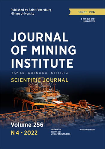
Evaluation of the efficiency of dry magnetic separation is based on comparing the values of Fetot extraction into the non-magnetic fraction (NMF) during DMS of feed size ore (εfeedFetot) and Fetot extraction into the NMF in the course of DMS of classified ore (εclassFetot). Predominance of the number of cases (75 %) with a negative value of εfeedFetot – εclassFetot difference was established. Negative values of difference indicate a decrease in Fetot loss into the NMF during separation of feed size ore mass regardless of magnetic induction values on the surface of the magnetic separator drum shell (Fig.1). In 17 % of cases, the difference between the values of Fetot extraction into the non-magnetic fraction for feed ore and classified ore does not exceed 0.6 %. For ore mass with the lump size less than 80 mm, the difference is εfeedFetot – εclassFetot<0.3%.
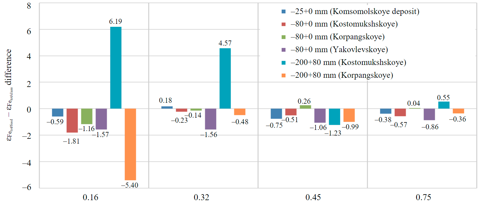
Fig.1. Diagram of a change in difference between values of Fetot extraction into NMF for feed ore and classified ore from the magnetic induction value on the surface of magnetic separator drum shell
Obvious differences are recorded in the DMS results for size classes –200+80 mm samples at magnetic induction values 0.16 and 0.32 T and are associated with dressability of the feedstock: the sample from the Kostomukshskoye deposit is characterized as difficult to beneficiate; the sample from the Korpangskoye deposit is easy to beneficiate. At magnetic induction of 0.45 and 0.75 T, εfeedFetot – εclassFetot difference does not exceed 1.5 %. This indicates that in the 80-200 mm size range of lumps, the size of impregnations, which in this case characterize the dressability of ore (coarsely impregnated – easy to beneficiate; finely impregnated – difficult to beneficiate), has a major effect on the DMS realized at magnetic induction values of 0.16 and 0.32 T. Increase of magnetic induction values to 0.45 and 0.75 T increases the specific magnetic force acting on the lump and contributing to obtaining similar technological parameters for the ore mass of feed size and after pre-screening. As a result of increase in magnetic field induction on the drum surface from 0.16 to 0.25 T, specific magnetic force acting on a particle with a height of 40 mm increases to a value equal to the specific magnetic force that acts on a particle of 1 mm height at induction of 0.16 T. An increase in magnetic induction value to 0.25 T significantly reduces the losses of magnetite iron with large lumps of ore and makes it possible to beneficiate crushed ore that is not classified by size under the same operating modes of the separator (gate position, drum rotation speed).
As a result of analysis of the materials of laboratory and enlarged laboratory studies of ferruginous quartzite samples from the deposits operated by plants of PAO “Severstal” Holding, a departure from the data of theoretical and experimental studies presented in [1, 9, 24] was recorded. This fact is presumably related to the design features of the separator used in the research.
The aim of the work is to provide grounds to the hypothesis of a possible realization of the DMS on ferruginous quartzites for the deposits operated by plants of PAO “Severstal” Holding at feed size after medium crushing (size class –80+0 mm) when the vibrating feeder is used for feeding ore mass into the separation zone. To achieve this goal, it is necessary to solve the following tasks:
- Analyze video material of magnetic separation process realized on a laboratory drum magnetic separator using the VSDC Video Editor.
- Based on results of physical experiments, to develop a kinematic separation model in Rocky DEM software package that adequately reflects the real process on the laboratory drum magnetic separator used.
- Develop a kinematic model of separator with an alternative option for transporting ore mass from the intake hopper to the magnetic separator drum, which ensures coincidence of overall dimensions of the transporter surface, location of intake hopper, height from the point of lumps breaking-off the transporter surface to the magnetic separator drum shell and movement speed of ore mass lumps along the transporters.
- Evaluate the movement of material on the surface of vibrating feeder chute of the laboratory drum magnetic separator in Rocky DEM software package from the intake hopper to the separator drum as well as ore mass passage along this path on a conveyor belt.
Methodology
Assessment of the influence of ore mass feeders to the separation zone on the efficiency of the DMS process is based on the analysis of material behavior in the magnetic separator space starting from the time the ore mass is unloaded from the intake hopper onto the transporter surface, in the process of moving along it to the separator working zone, to separation – formation of magnetic and non-magnetic fractions in the magnetic field action area.
Analysis of an ore sample movement from the time the lumps leave the vibrating feeder surface and along the course of their movement on the surface of the magnetic separator drum shell in the process of the DMS based on video recording results. Video recording was made by a camera with a resolution of 1,920×1,080 and a frequency of 240 frames per second. Processing of video material and construction of the movement trajectories of lumps are realized in VSDC Video Editor using the Motion tracking module (Fig.2), which allows to automatically create the movement trajectories of objects in video recording. The fragment of the video file presented in the window of the VSDC Video Editor software (Fig.2), which characterizes the entire video recording, is rotated counterclockwise by 90°. It should be noted that in order to track the position of lumps moving at an average speed of 1.73 m/s, a preliminary preparation of the video file is required – more than eight-fold slowing down of playback speed (to 12 % of its original speed).
Construction of the lump movement trajectory along the surface of magnetic separator drum is accomplished as follows: determination of the point relative to which the construction of trajectories will start (point of free fall start on coming-off the vibrating feeder chute); setting the area around the tracked object; tracking the movement of selected object using a special inbuilt algorithm of video editor: positioning the object on the drum spreader shell surface on each frame of video recording (setting markers).
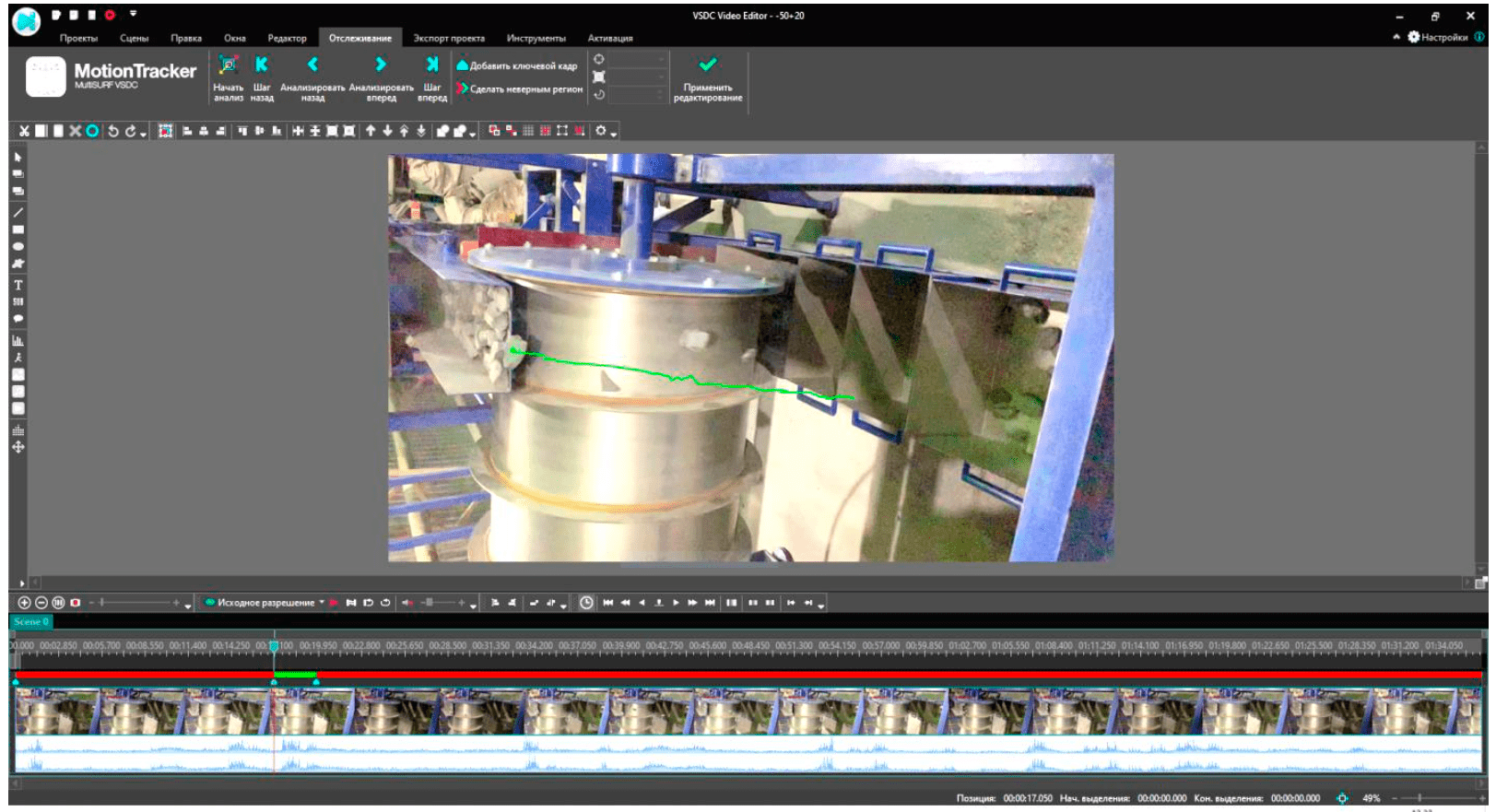
Fig.2. Window of VSDC Video Editor software
A chain formed from sequential markers (Fig.2, green line) determines the movement trajectory of an ore mass lump from the edge of vibrating feeder chute to the intake hopper for separation products. This video editor allows making changes to the trajectory by setting reference points on the time scale adjusting the selection area and re-building a section of the trajectory that does not meet the user's requirements.
In the study, a laboratory drum magnetic separator of SMBS-L series (NPO “Erga”) was used. The design of this separator model, namely the presence of side walls at the vibrating feeder chute and the magnetic separator drum shell which form a directed movement of ore mass flow, did not allow to evaluate the layer forming on the vibrating feeder and its changes during movement from the place of ore unloading from the intake hopper to the edge of the vibrating feeder chute. For this, computer simulation of the process of rock mass movement in the space of a magnetic separator was conducted in Rocky DEM software package, which uses the discrete element method for modeling [25-27]. Papers [28-30] describe a successful application of Rocky DEM to solve the problems of substantiating the optimal design parameters and operating modes of beneficiation equipment.
A three-dimensional model of a laboratory magnetic separator used in physical experiments (Fig.3, a) was developed in AutoCAD and imported into Rocky DEM in STL format.
To confirm the hypothesis about a positive effect of the applied ore mass transporter to the separation zone (vibrating feeder), an alternative version of the device was developed in AutoCAD ensuring ore movement from the intake hopper to the magnetic separator drum – a conveyor with lateral restraints (Fig.3, b). Dimensions of the transporting surface of both devices (width and length), location relative to the intake hopper, height from the point of lump separation from the surface of the transporters to the magnetic separator drum shell are the same. Ore loading from the intake hopper to the transporter is performed without using the devices designed for batch unloading, the material moves by gravity. The conveyor belt speed (0.2 m/s) is selected so as to ensure a similar speed of ore mass lumps movement from the intake hopper to the surface of the magnetic separator drum along the vibrating feeder (0.2 m/s).
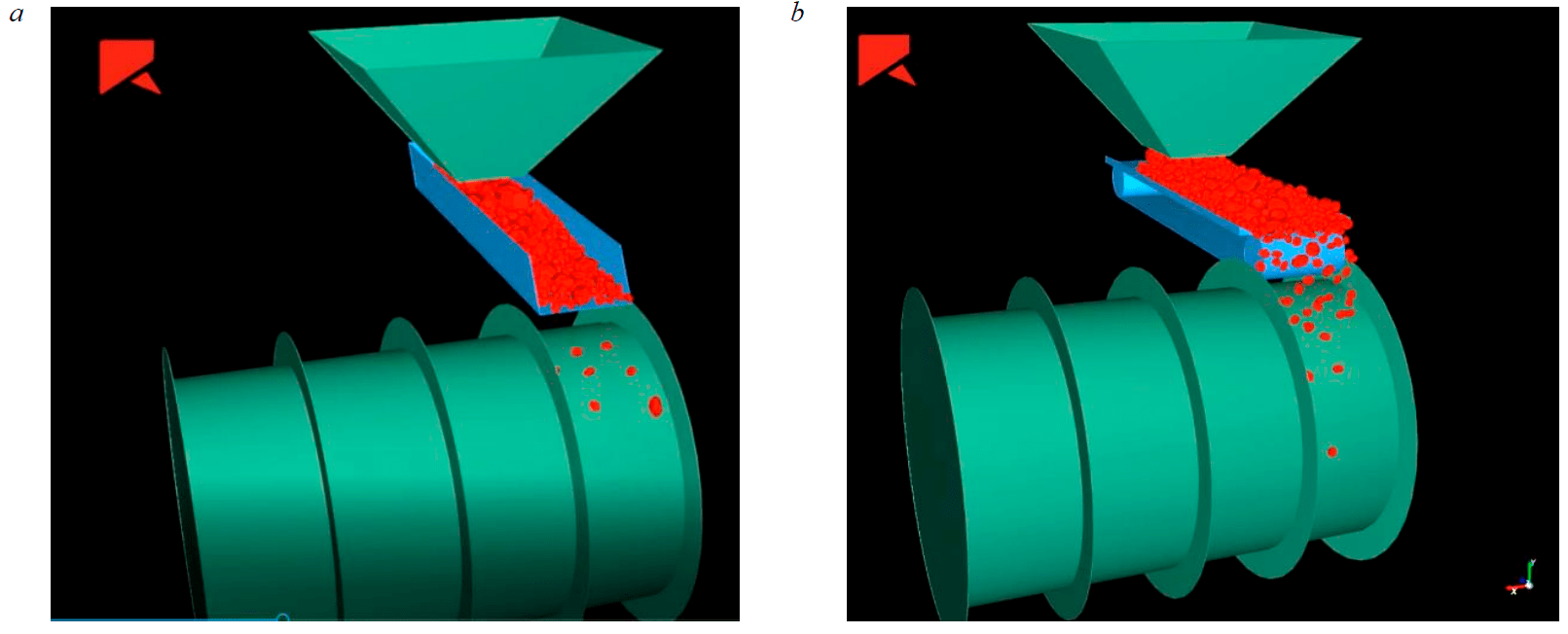
Fig.3. Magnetic separator model in Rocky DEM software package (transportation systems – a vibrating feeder (a) and a conveyor belt (b)
To achieve highly realistic results of Rocky DEM modeling, ore mass is represented as a set of polyhedrons characterized by a shape determined by the ratio of the parallelepiped sides into which the polyhedron is inscribed, and a quantitative ratio of the size classes that make up the sample identical to the real test sample. Stress-strain characteristics of the sample used for modeling were determined from the results of studying the characteristics of ferruginous quartzite samples on the MTS 816 Rock Test System*. Friction coefficient of “ore – steel” pair characterizing the interaction of lumps with the surface of vibrating feeder chute made of steel was determined experimentally. The experiment consisted in finding the inclination angle of the vibrating feeder chute to the horizon, which ensures spontaneous rolling of lumps of the studied ore. Internal friction coefficient which characterizes the interaction of ore lumps with each other, based on reference values, is taken equal to 0.7.
It should be noted that there is no possibility in the Rocky DEM software package to simulate the interaction of ore mass lumps having magnetic properties with a magnetic field on the surface of the magnetic separator drum shell created by permanent magnets.
Discussion of results
Movement of ore mass lumps in the process of the DMS was analyzed using the material of initial size range –80+0 mm and narrow size classes formed by screening (–80+50, –50+20 and –20+0 mm). Construction of the trajectories and quantitative evaluation of batches were carried out in the steady-state operating mode of separator which is characterized by a uniform movement of ore mass along the surface of the vibrating feeder chute without formation of heaps and gaps between the batches.
In the course of video material processing, it was found that for ferruginous quartzites represented mainly by their magnetite variety the minimum lump size for which a movement trajectory can be constructed is 20 mm. Construction of the movement trajectory of lumps less than 20 mm is not possible due to their low colour contrast relative to the background (surface of the magnetic separator drum shell). Therefore, for ore mass lumps with a particle size less than 20 mm, a qualitative assessment of their movement character from the intake hopper to tanks with magnetic and non-magnetic separation products was applied. From the vibrating feeder the material came off mostly as batches and less frequently as single lumps. Deviations in the character of movement on the drum surface were not recorded – non-magnetic and magnetic fractions freely fell into the corresponding receiver tanks. The material of the size close to 0 mm moved similarly.
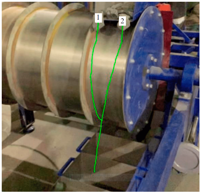
Fig.4. Movement trajectories of ore lumps on the surface of magnetic separator drum shell 1 – a lump with magnetic properties; 2 – a non-magnetic lump
Figure 4 presents an example of movement trajectories of ore lumps with a size of
–80+50 mm characteristic of the entire sample volume of size classes –80+50 and –50+20 mm differing in magnetic properties: the first one is closer to the middle of the drum, moves to the receiving tanks of separation products along the surface of the magnetic separator drum shell; the second one, closer to the drum edge, moves tangentially towards rock tanks (farthest from the separator drum).
A batch character of ore mass arriving to the surface of the magnetic separator drum after leaving the vibrating feeder chute was recorded regardless of the size class (Fig.5). It has been ascertained that with growing size of lumps, time interval between the batches increases: for size class of –80+50 mm it is 336 ms; for –50+20 mm – 125 ms; for –20+0 mm – 23 ms. Time interval between batches of feed ore is 77 ms, which is two times shorter than the average interval between batches for the combined size class –80+0 mm of classified ore.
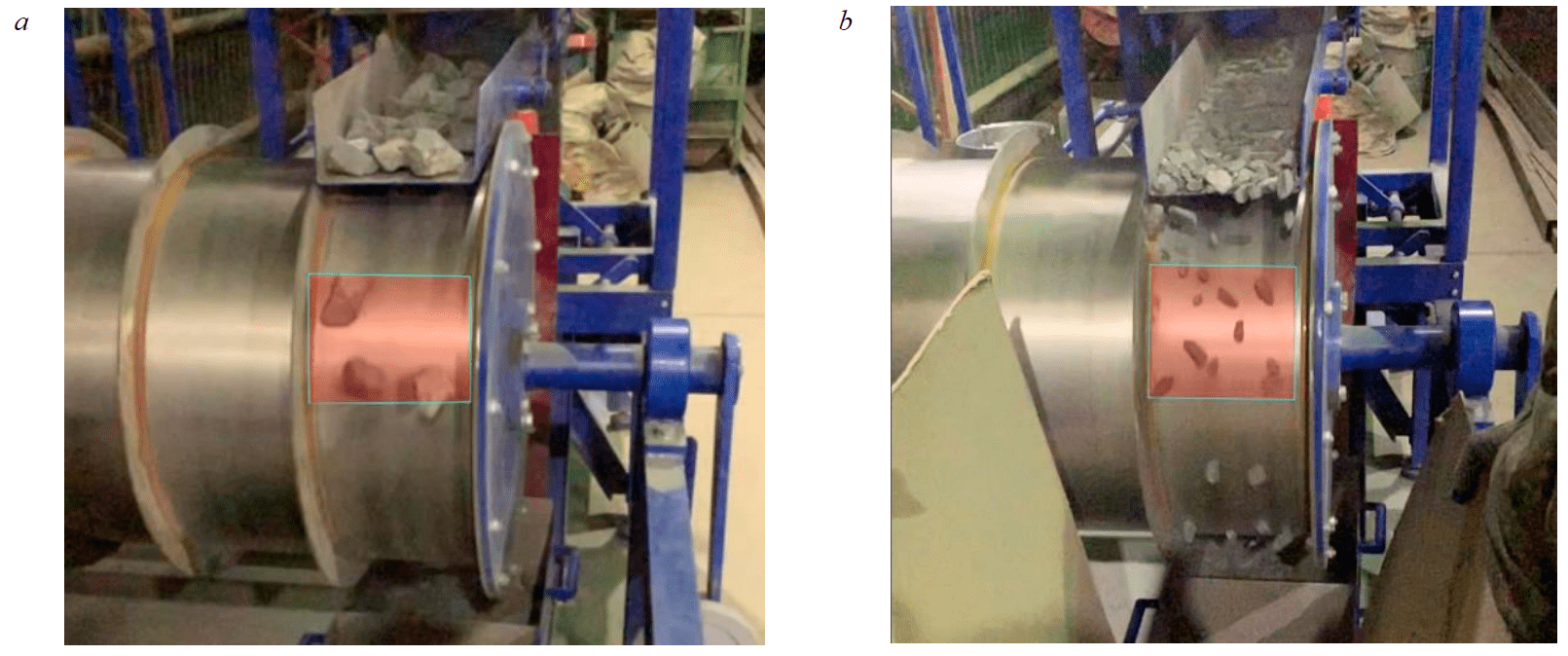
Fig.5. Movement of ore mass lumps in the space of a magnetic separator: size classes –80+50 (a) and –50+20 mm (b)
A decreasing time range between batches coming from the vibrating feeder chute to the surface of the magnetic separator drum shell in ore sample of the initial size range –80+0 mm is due to deceleration in the movement of large lumps (–80+20 mm) caused by lumps less than 20 mm. It is noted that a monolayer formed from the lumps of size class –20+0 mm on the surface of the drum shell which causes a decrease in the movement speed of large lumps and increase in the distance between the magnet and the lump does not adversely affect the separation efficiency of large lumps.
Study of ore mass movement in a kinematic model of the magnetic separator created in Rocky DEM software package made it possible to expand the studied movement area of the material – to analyze the path from the time of ore mass unloading from the intake hopper to the transporter surface as well as in the process of moving along the surface of the magnetic separator drum shell which does not have the force of attracting magnetic ore lumps.
A comparative analysis of ore mass lumps movement along the surface of transporters showed that for the first option with the use of the vibrating feeder in the transporting system of ore mass from the intake hopper to the magnetic separator drum there is a decrease in layer thickness from the outlet slot of the intake hopper to the chute end from 55 to 10 mm (Fig.6).
When ore is moving to the surface of the magnetic separator drum by the conveyor belt, the layer thickness remained constant along the movement path and amounted to 55 mm. Minor layer height fluctuations on the conveyor belt surface are associated with lump shape and size at a particular point on the conveyor and are smoothed in a certain area when assessing the height of the layer.
It has been ascertained that at the same speed characteristics of ore movement on the surface of transporters, the number of lumps in a batch after transporting ore on the conveyor belt increases four-fold: in case of transporting by the vibrating feeder – an average of 10 lumps/batch (Fig.7, a); in case of conveyor transportation (Fig.7, b), to 40 lumps of ore mass are simultaneously present in the study area. The time spent on separating the simulated volume of the material decreased, at least, two-fold when the material moves from the intake hopper to the surface of magnetic separator drum.
Beginning of the study area is determined by an average contact line between ore mass lumps after the free fall trajectory with the surface of the magnetic separator drum shell at the beginning of the magnetic field influence domain. The reason for the increased continuous flow in the study area is the impossibility to form a monolayer flow when the conveyor belt is used.
Use of vibrating feeder for transporting ore mass from the intake hopper to the magnetic separator drum ensures formation of a monolayer with a thickness close to the maximum size of a lump of the studied ore sample; batch character of ore mass arriving to the surface of the magnetic separator drum after leaving the vibratory feeder chute, regardless of the size class. The accepted mutual arrangement of the vibrating feeder chute and the magnetic system forms a free fall area (see Fig.6, a), which allows increasing the distance between lumps in the separation zone and, thus, minimizing the influence of lumps on each other.
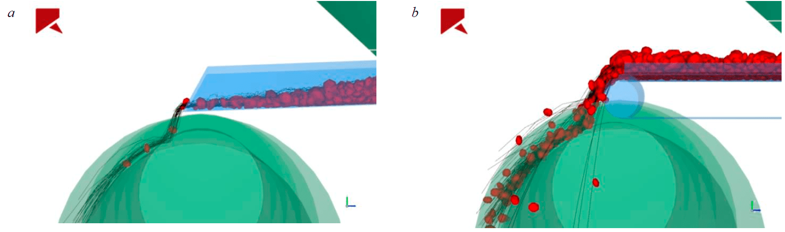
Fig.6. Ore mass movement from intake hopper to magnetic separator drum in Rocky DEM software package by vibrating feeder (a) and conveyor belt (b)
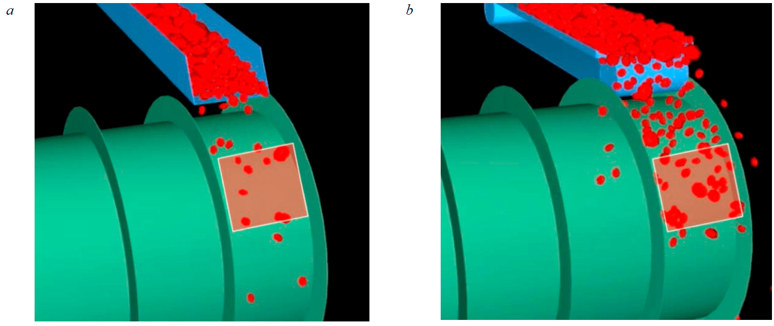
Fig.7. Influence domain of magnetic field in simulated magnetic separator when using vibrating feeder (a) and conveyor belt (b) for ore transportation
Conclusion
Results of the research based on analysis of video recording data of physical simulation process implemented on a laboratory drum magnetic separator of SMBS-L series (NPO “Erga”), in VSDC Video Editor and mathematical modeling of the DMS implementation on its virtual prototype in Rocky DEM software package indicate a possibility of performing the DMS of ferruginous quartzites of size class –80+0 mm (after medium crushing) without pre-preparation when a vibrating feeder is used for feeding ore mass to the separation zone.
Use of a vibrating feeder as a unit for feeding the material to the working area of a magnetic separator allows: forming a monolayer on the surface of the vibrating feeder chute with a thickness close to the maximum size of a lump of separated ore; implement batch feeding of material to the separation zone; increasing the distance between lumps in the separation zone when passing through the free fall area. Such movement of ore mass lumps in the working zone of the separator – in the action zone of the magnetic field – ensures an efficient separation into magnetic and non-magnetic products regardless of the lump size in the considered size range of 0-80 mm eliminating the need to classify the material in order to form narrow size classes.
The expansion of this work is supposed to increase productivity of the equipment achieved by reducing the amount of material fed in the magnetic separator drum by removing the product enriched in useful component (Fetot) at the stage of transporting ore mass from the intake hopper to the separation zone. It is possible to remove the beneficiated product by incorporating a grizzly grate into the transporting vibrating feeder (following the example of the transporting vibrating feeder chute of the energy-dispersive fluorescent separator [31-33].
References
- Kretov S.I. Improving the technical and economic performance of beneficiation of hematite-containing magnetite quartz by using dry magnetic separation prior to grinding: Avtoref. dis. … kand. tekhn. nauk. Moscow: Moskovskii gosudarstvennyi gornyi universitet, 2017, p. 17 (in Russian).
- Chanturia V.A., Shadrunova I.V., Gorlova O.E. Innovative Processes of Deep and Environmentally Safe Processing of Technogenic Raw Materials in the Conditions of New Economic Challenges. Sustainable development of mountain territories. 2021. Vol. 13. N 2 (48), p. 224-237 (in Russian). DOI: 10.21177/1998-4502-2021-13-2-224-237
- Chanturia V.A., Shadrunova I.V., Gorlova O.E., Kolodizhnaya E.V. Evelopment of Technological Innovations of Deep and Complex Processing of Technogenic Raw Materials in the Conditions of New Economic Challenges. Izvestija Tulskogo gosudarstvennogo universiteta. Nauki o zemle. 2020. N 1, p. 159-171 (in Russian). DOI: 10.46689/2218-5194-2020-1-1-159-171
- Lizunkin M.V. Substantiation of geotechnology for underground mining of ore deposits of complex structure: Avtoref. dis. … d-ra tekhn. nauk. Chita: Zabaikal'skii gosudarstvennyi universitet, 2020, p. 48 (in Russian).
- Konev A.V., Shulgina K.A., Mironova Zh.V. et al. Economic modeling of conditions for using pre-concentration to increase the efficiency of mining and metallurgical plants. VI mezhdunarodnyi kongress “Tsvetnye metally i mineraly 2014”, 15-18 sentyabrya 2014, Krasnoyarsk, Rossiya. OOO “Legkie metally”, 2014, p. 724-730 (in Russian).
- Tzarev S.A., Horohonov Y.B. The Analysis of Methods of Ore Pre-Concentration. Proceedings of Irkutsk State Technical University. 2009. N 2 (38), p. 23-27 (in Russian).
- Fadina A.V., Andreev E.E., Lvov V.V. Pre-concentration of raw materials using sensor-based sorting. Journal of Mining In-stitute. 2013. Vol. 206, p. 139-142 (in Russian).
- Kulikov V.I., Fedorov Yu.O. New possibilities and prospects for pre-concentration of ores based on X-ray radiometric sepa-ration technology. Mezhdunarodnoe soveshchanie “Problemy i perspektivy effektivnoi pererabotki mineral'nogo syr'ya v 21 veke” (Plaksinskie chteniya – 2019), 9-14 sentyabrya 2019, Irkutsk, Rossiya. Reprotsentr A1, 2019, p. 101-105 (in Russian).
- Varichev A.V., Ugarov A.A., Efendiev N.T. et al. Innovative solutions in iron ore raw materials production at Mikhailovsky GOK (Mining and Processing Plant). Fiziko-tekhnicheskie problemy razrabotki poleznykh iskopaemykh. 2017. N 5, p. 141-153 (in Russian). DOI: 10.15372/FTPRPI20170516
- Karmazin V.V. Estimation of potential dressability of iron ore raw materials based on mineral liberation parameters. Chernaya metallurgiya. Byulleten' nauchno-tekhnicheskoi i ekonomicheskoi informatsii. 2017. N 12 (1416), p. 11-18 (in Russian).
- Bhoja S., Tripathy S., Murthy Y. et al. Influence of Mineralogy on the Dry Magnetic Separation of Ferruginous Manganese Ore – A Comparative Study. Minerals. 2021. Vol. 11. Iss. 2. N 150. DOI: 10.3390/min11020150
- Xiong D., Lu L., Holmes R.J. Developments in the physical separation of iron ore: magnetic separation. Iron Ore. Mineralogy, Processing and Environmental Sustainability. 2015, p. 283-307. DOI: 10.1016/B978-1-78242-156-6.00009-5
- Ezhov A.M., Shvaljov Y.B. Dry Magnetic Separation of Iron Ore of the Bakchar Deposit. Procedia Chemistry. 2015. Vol. 15, p. 160-166. DOI: 10.1016/j.proche.2015.10.026
- Jianjun Liu, Zixing Xue, Zhenhai Dong et al. Multiphysics Modeling Simulation and Optimization of Aerodynamic Drum Magnetic Separator. Minerals. 2021. Vol. 11. Iss. 7. N 680. DOI: 10.3390/min110706804
- Zong Q.X., Fu L.Z., Bo L. Variables and Applications on Dry Magnetic Separator. Proceedings of the 3rd International Conference on Advances in Energy and Environmental Research (ICAEER 2018), 10-12 August 2018, Guilin, China. E3S Web Con-ference, 2018. Vol. 53, p. 1-9. DOI:10.1051/E3SCONF/20185302019
- Mohanty S., Nayak B., Bhattacharyya K.K. High intensity magnetic separation of iron ore slime and its limitations. Pro-ceedings of the XI International Seminar on Mineral Processing Technology, 15-17 December 2010, Jamshedpur, India, p. 173-178.
- Baawuah E., Kelsey С., Addai-Mensah J., Skinner W. A Novel Pneumatic Planar Magnetic Separator for Magnetite Bene-ficiation: A Focus on Flowsheet Configuration. Minerals. 2020. Vol. 10. Iss. 9. N 759. DOI: 10.3390/min10090759
- Pelevin A.E., Sytykh N.A., Cherepanov D.V. Particle size impact on dry magnetic separation efficiency. Mining informa-tional and analytical bulletin. 2021. N 11-1, p. 293-305 (in Russian). DOI: 10.25018/0236_1493_2021_111_0_293
- Sedinkina N.V., Gorlova O.E., Gmyzina N.V., Degodya E.Yu. Study of a possibility of enrichment of fine-crushed magnetite ore by dry magnetic separation. Ferrous Metallurgy. Bulletin of Scientific, Technical and Economic Information. 2019. Vol. 75. N 5, p. 564-571 (in Russian). DOI: 10.32339/0135-5910-2019-5-564-571
- Khramov A.N. Optimization of crushing size in preparation of fluorite ore for pre-concentration. Mining informational and analytical bulletin. 2011. N 5, p. 147-153 (in Russian).
- Tereshchenko S.V., Shibaeva D.N. Ore quality improvement by pre-concentration: Theory and practice. Gornyi zhurnal. N 9, p. 60-65 (in Russian). DOI: 10.17580/gzh.2020.09.08
- Tereshchenko S.V., Shibaeva D.N., Kompanchenko A.A., Alekseeva S.A. Research of the influence of material composition and size of iron quartzites of the Olenegorsk deposit on the results of dry magnetic separation. Obogashchenie rud. 2020. N 6, p. 15-20. DOI: 10.17580/or.2020.06.03
- Shibaeva D.N., Tereschenko S.V., Kompanchenko A.A. Analysis of the effect of dry magnetic separation on the process of ferruginous quartzites disintegration. Minerals. 2021. Vol. 11. Iss. 8. N 797. DOI: 10.3390/min11080797
- Karimi P., Khodadadi Darban A., Mansourpour Z. A finite element model to simulate magnetic field distribution and la-boratory studies in wet low-intensity magnetic separator. Journal of Mining and Environment. 2019. Vol. 10. Iss. 3, p. 717-727. DOI: 10.22044/jme.2019.8132.1680
- Beloglazov I.I., Ikonnikov D.A. Application of the Discrete Element Method for Modeling of Rocks Crushing in a Jaw Crusher. Izvestiya vuzov. Priborostroenie. 2016. Vol. 59, N 9. p. 780-786 (in Russian). DOI: 10.17586/0021-3454-2016-59-9-780-786
- Arsentyev V.А., Blekhman I.I., Blekhman L.I. et al. Dynamics of particles and discrete element methods as a tool of studies and optimization of natural and man-made materials processing. Obogashchenie rud. 2010. N 1, p. 30-35 (in Russian).
- Xiangjun Qiu. DEM Simulations in Mining and Mineral Processing. 7th International Conference on Discrete Element Methods, 1-4 August 2016, Dalian, China. Springer, 2016, p. 37-43. DOI: 10.1007/978-981-10-1926-5_5
- Chitalov L.S. Development of an integrated method for evaluating the efficiency of grinding sulfide copper-nickel ores: Avtoref. dis. … kand. tekhn. nauk. St. Petersburg: Sankt-Peterburgskii gornyi universitet, 2021, p. 24 (in Russian).
- Beloglazov I.I., Stepanyan A.S., Feoktistov A.Yu., Yusupov G.A. Disintegration process modeling for a jaw crusher with complex jaws swing. Obogashchenie rud. 2018. N 2, p. 3-8 (in Russian). DOI: 10.17580/or.2018.02.01
- Aminov V.N., Kameneva E.E., Ustinov I.D. Modeling of rock material crushing for crushed stone production. Obogashchenie rud. 2017. N 4, p. 3-6 (in Russian). DOI: 10.17580/or.2017.04.01
- Korotkevich V.A., Kukharenko I.E., Belyak A.A., Korotkevich E.V. Innovative technologies and equipment in pre-concentration of mineral raw materials. Dobyvayushchaya promyshlennost. 2017. N 2, p. 168-172 (in Russian).
- Zabolotskiy A.I., Nerushchenko Ye.V., Rassulov V.A. Results of Research on the Applicability of Pre-Enrichment Methods for Gold Ores from Highland Gold Mining Ltd Deposits. Ratsionalnoe osvoenie nedr. 2020. N 4, p. 64-70 (in Russian). DOI: 10.26121/RON.2020.57.68.008
- Zavyalov S. S., Mamonov R. S. Mixed-type dry pretreatment technology for goldbearing ore. MIAB. Mining informational and analytical bulletin. 2021. N 11-1, p. 338-345 (In Russian). DOI: 10.25018/0236_1493_2021_111_0_338