
A new formula for calculating the required thickness of the frozen wall based on the strength criterion
- 1 — Ph.D., Dr.Sci. Head of Laboratory Mining Institute of the Ural Branch of the RAS ▪ Orcid
- 2 — Ph.D., Dr.Sci. Head of Department Mining Institute of the Ural Branch of the RAS ▪ Orcid ▪ Scopus
Abstract
The study delves into the elastoplastic deformation of a frozen wall (FW) with an unrestricted advance height, initially articulated by S.S.Vyalov. It scrutinizes the stress and displacement fields within the FW induced by external loads across various boundary scenarios, notably focusing on the inception and propagation of a plastic deformation zone throughout the FW's thickness. This delineation of the plastic deformation zone aligns with the FW's state of equilibrium, for which S.S.Vyalov derived a formula for FW thickness based on the strength criterion. These findings serve as a pivotal launchpad for the shift from a one-dimensional (1D) to a two-dimensional (2D) exploration of FW system deformation with finite advance height. The numerical simulation of FW deformation employs FreeFEM++ software, adopting a 2D axisymmetric approach and exploring two design schemes with distinct boundary conditions at the FW cylinder's upper base. The initial scheme fixes both vertical and radial displacements at the upper base, while the latter applies a vertical load equivalent to the weight of overlying soil layers. Building upon the research outcomes, a refined version of S.S.Vyalov's formula emerges, integrating the Mohr – Coulomb strength criterion and introducing a novel parameter – the advance height. The study elucidates conditions across various soil layers wherein the ultimate advance height minimally impacts the calculated FW thickness. This enables the pragmatic utilization of S.S.Vyalov's classical formula for FW thickness computation, predicated on the strength criterion and assuming an unrestricted advance height.
The study was carried out with financial support from the Ministry of Higher Education and Science of the Russian Federation within the framework of project N 122030100425-6.
Introduction
The construction of mine shafts in waterlogged and unstable soils typically involves various methodologies [1, 2]. Within potash mining operations, artificial ground freezing emerges as a prevalent technique, owing to the distinctive attributes of the deposits – notably, the water solubility of productive salt layers and the imperative to shield mine workings from groundwater infiltration [3, 4]. Through artificial ground freezing, a frozen wall (FW) is established, serving to waterproof the nascent mine opening and reinforce its inherently unstable walls. The FW's thickness must meet stringent criteria, contingent upon the strength and creep characteristics of the soils [5-7].
Adherence to current regulations, such as SP 248.1325800.2016 and SNiP 32-02-2003, mandates that the design of specialized methodologies for excavating underground structures aligns with directives outlined in VSN 189-78. These directives offer straightforward calculation methodologies for determining FW thickness, incorporating both the strength-based Lame – Gadolin formula and the Domke formula.
The Lame – Gadolin formula exclusively considers the elastic deformation of the FW and finds utility under low loads, whereas the Domke formula incorporates elastoplastic deformation to a certain extent and proves applicable over a broader, albeit still restricted, range of loads [8]. Both formulas rely on the Tresca – Saint-Venant plasticity condition [9, 10], which exhibits limited applicability to frozen soils [11]. A more accurate assessment of the transition to the plastic deformation zone in frozen soils necessitates the consideration of alternative criteria, such as Mohr – Coulomb [12-14] and Drucker – Prager [15] or their respective modifications [16, 17]. The parameters of these criteria encompass the strength properties of frozen soils, namely adhesion C and the angle of internal friction φ[18]. It is noteworthy that under conditions involving freezing at considerable depths and subject to high uniform compressive pressure, both the Mohr – Coulomb and Drucker – Prager criteria necessitate modifications due to their limited applicability [19].
The strength properties, represented by adhesion C and the angle of internal friction φ, serve as initial parameters in the renowned formula developed by S.S.Vyalov for determining the thickness of the FW according to strength requirements [20, 21]:
where R – denotes the radius of the internal boundary of the FW, m; P – represents the external load, Pa.
While formula (1) is not codified in regulatory literature, it is frequently employed in the analysis of FW thickness based on strength criteria. This formula is applicable to scenarios involving an infinite FW cylinder, which technically corresponds to shaft sinking with unrestricted advance height h. For situations with finite advance height, S.S.Vyalov also derived a corresponding calculation formula:
where σc is the uniaxial compressive strength of frozen soil, MPa.
However, in deriving formula (2), other, more simplified approximations were utilized, leading to significant overestimations of FW thickness when considering realistic ranges of advance heights (3-12 m).
Moreover, researchers often resort to more intricate rheological models, such as the Nishihara model [21, 22], the Barcelona model [23], etc., when analyzing the nonlinear deformation of frozen soils. However, the implementation of these complex models, which require a greater number of parameters, poses challenges in their determination through laboratory tests. Consequently, their application in practical scenarios for predicting the stress-strain state of soil mass during mine shaft construction becomes unfeasible.
Relatively straightforward models of nonlinear deformation in frozen viscoelastic-plastic media are employed to compute FW thickness based on the creep condition, which, for certain soil types, holds comparable importance to the strength condition [24-26]. Computation based on the creep condition involves identifying the FW thickness at which the maximum radial displacement of its inner wall, induced by external loading on the outer wall, remains within the predetermined maximum permissible value Δ over a specified time period tp. The determination of Δ draws upon shaft sinking technology or the permissible deflection value of the freeze pipes [8, 27]. However, this paper specifically focuses on calculating FW thickness precisely according to the strength condition (or the ultimate stress state).
Formula (1) for computing FW parameters based on strength conditions fails to consider several significant physical factors:
- finite advance height;
- partial transmission of lateral thrust pressure by surrounding unfrozen soils;
- the initial deformed state of soils due to thermal deformation of solid particles and expansion of water during freezing in the pores;
- inhomogeneous temperature field within frozen soils;
- vertical load.
In previous studies [13, 14, 28], efforts were made to amend formula (1) by considering factors 2, 3, and 4. Factors 1 and 5 influencing the stress-strain state of frozen soils were also addressed, albeit through a different methodological framework – numerical simulation of coupled thermohydromechanical processes [23, 29, 30]. However, devising a universal formula to determine the requisite FW thickness for arbitrary cases proved unattainable.
This paper explores the feasibility of formulating an analytical calculation formula to determine FW thickness based on the limiting stress state, integrating the final advance height. It proposes a modification of formula (1), incorporating a new parameter – the advance height.
Methodology
The scenario of unrestricted advance height
The study delves into the elastoplastic deformation of frozen soils through a simplified mathematical approach. Preceding the transition to a two-dimensional formulation with finite advance height, the analysis begins with a simpler one-dimensional scenario involving a hollow cylinder composed of frozen soils, featuring infinitely large advance height, and internal and external radii 𝑎 and 𝑏 respectively (Fig.1). This formulation was initially explored in the source [3].
A uniform load is applied to the outer boundary of the computational domain, while an unloaded surface condition is specified on the inner boundary. The soil is assumed to be homogeneous and isotropic, with the stress-strain state exhibiting plane deformation. Consequently, rotational symmetry prevails in both the geometry and boundary conditions of the problem, suggesting that the solution maintains this symmetry as well. Under this circumstance, only radial displacements deviate from zero. The mathematical formulation of the problem includes:
- equilibrium equation:
- elastic deformation zone:
- plastic flow zone defined by the Mohr –Coulomb criterion:
- boundary conditions
where σr and σθ – represent the radial and tangential (angular) components of the stress tensor, respectively, Pa; K – denotes the bulk modulus of elasticity, Pa; G – signifies the shear modulus, Pa; εr and εθ – denote the radial and tangential components of the strain tensor, respectively; u – stands for radial displacement. m; ξ – represents the boundary between the elastic zone and the plastic flow zone, m.
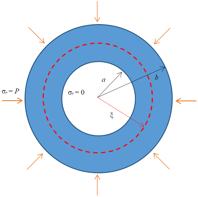
Fig.1. Geometry of the computational domain when considering unrestricted advance height
Conventionally, compressive stresses are assigned a positive sign, while tensile stresses are assigned a negative sign [31]. Two stress conditions were chosen as boundary conditions between the two zones, with the displacement continuity condition being implicitly satisfied when equalities (10) hold. The parameter ξ is of particular interest, along with the function σr, σθ, etc.
As highlighted in the source [27], the initiation and progression of the elastoplastic deformation zone originate from the inner boundary of the FW. It is postulated that the FW loses its load-bearing capacity once the plastic flow zone extends across the entire FW thickness, making initial contact with its outer boundary. This state of limiting equilibrium determines the calculated FW thickness.
Previously, the solution to the system of equations (5)-(10) was only partially explored, focusing primarily on stresses, which sufficed for determining the maximum load on the FW. However, in terms of studying the distribution of deformations and displacements, they are also of interest for further research aimed at modifying formula (1). Nevertheless, obtaining the distribution of displacements within the frozen soil volume analytically is unfeasible, necessitating numerical solution of problem (4)-(10). Consequently, to devise a numerical calculation scheme, it was imperative to enhance and amend the system of equations (4)-(10) with an associated law governing plastic flow [32, 33]:
and reformulate Hooke’s law (6)-(7) as:
where εr(p) and εθ(p) – represent the plastic components of the radial and tangential components of the strain tensor, respectively; λ – denotes the plastic factor; F – denotes the yield surface determined by condition (8).
The increase in plastic deformations within the plastic flow zone is assumed to follow the associated flow law. While this law is relatively straightforward, it relies on simplifications that may not fully hold true for frozen rocks and soils [34]. Specifically, concerns arise regarding the assumption of coaxiality of the vectors of the principal stresses, as well as the linear and plastic components of the principal deformations [35]. However, in the present case where tangential components of the stress and strain tensors are zero, the assumption of vector coaxiality remains valid.
Numerical solution of problems (4), (7)-(13) was executed using Wolfram Mathematics software, employing the finite difference method. Loading of the FW was carried out iteratively. At each iteration step i = 1, … n, a load equal to ΔPi = P/n. was applied to the outer boundary of the FW. Subsequently, in each cell of the computational domain, the fulfillment of the condition
was verified, and if violated, the increase in the plastic part of the strain tensor was computed in accordance with law (11).
The scenario of finite advance height
was the subsequent focus of the study, involving an analysis of the stress-strain state of the FW. This is achieved by slightly modifying the original equilibrium equation (4) to include an additional term accounting for shear stress τrz [8]:
where z – denotes the vertical coordinate, m.
It is crucial to note that the emergence of tangential stresses and deformations results in the loss of vertical symmetry in the problem, rendering the state of the FW no longer plane-deformed.
To investigate and determine the form of the function τrz (r, z), numerical simulation methods were employed to analyze the stress-strain state in the FW, while considering the rotational symmetry of the problem. This approach allows the reduction of the spatial dimension from 3D to 2D. The numerical solution to the two-dimensional problem was attained using the finite element method within the FreeFEM++ software package. Additionally, alongside the equilibrium equation (15) along the radial axis, the equilibrium equation in the vertical direction was also considered:
where σz – represents the vertical component of the stress tensor, Pa.
For simplicity, an elastic formulation of the problem is considered. At the lower base of the FW cylinder, the condition of zero vertical displacements was specified, while at the upper base, two possible calculation schemes were considered. In the first case (Fig.2, a), both vertical and horizontal movements were recorded, following the classical formulation by S.S.Vyalov [27]. In the second case (Fig.2, b), a vertical load corresponding to the weight of the overlying soil layers (q = 1.29 MPa) was applied. At the inner extreme point of the upper base (𝑟 = 𝑎), both movements were fixed. Boundary conditions at the upper base, corresponding to the second design scheme, were also utilized in [24, 26], and according to the authors, are more justified from a physics standpoint. However, consideration of the first calculation scheme (as a secondary one) is also valuable for comparative analysis purposes.
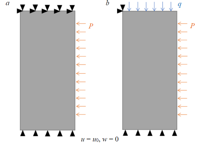
Fig.2. Calculation schemes for the two-dimensional problem of stress-strain state in FW: a – first scheme, b – second scheme
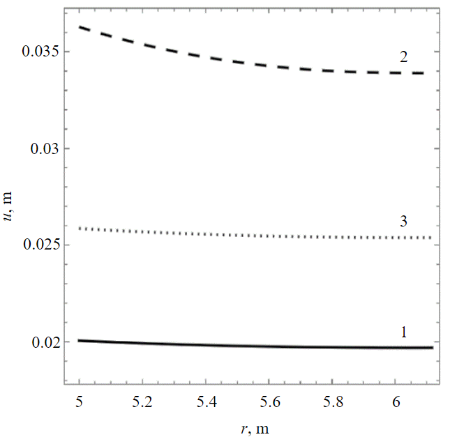
Fig.3. Distribution of absolute values of radial displacements in the FW volume 1 – beginning of the onset of plastic deformations; 2 – limit state of equilibrium (elastic-plastic deformation); 3 – limit state of equilibrium (elastic deformation)
In the first calculation scheme, the vertical displacement 𝑤 was set to zero, and the horizontal displacement 𝑢 was determined by the function u0= a/r. This function can be interpreted as the equilibrium displacement of the internal boundary of the FW, achieved in a given horizontal section of the soil mass by the time the concrete lining is erected. It is assumed that the displacement on the internal boundary of the FW at the upper base is 𝑢0 = 0.5 cm. Subsequently, following the formalism of the finite element method [36], the analysis transitioned to the variational formulation of the axisymmetric problem in elasticity theory, incorporating the introduction of shape functions. Specifically, first-order shape functions were introduced for displacements and zero-order shape functions for stresses.
Results and discussion
The scenario of unrestricted advance height
The calculated distribution of absolute radial displacement values within the frozen soil volume is depicted in Fig.3. Real radial displacements are represented with a negative sign. The calculations were conducted based on the follo-wing parameters: P = 0.86 MPa; K = 981 MPa; G = 869 MPa; Λ = 1.58; Λ‾ = 4.02 MPa; a = 5 m; b = 6.12 m, corresponding to silt [5]. Alongside the curve illustrating elastoplastic deformation of the FW, additional curves showcasing elastic deformation of the FW under a load corresponding to the onset of plastic deformation are included. The minimum (absolute value) displacements align with the initiation of plastic deformation (with an external load slightly lower at 0.67 MPa), while the maximum (absolute value) displacements correspond to elastoplastic deformation accounting for plastic flow. Notably, displacement distributions in all three scenarios exhibit uniformity across the FW thickness. The relative difference δu between displacements in elastic and elastoplastic conditions under an external load of 0.86 MPa ranges from 34 to 39 % relative to the smallest displacement value. This variance significantly relies on the soil type and the temperature at which the strength characteristics of frozen soils were assessed (refer to the Table). Data on the physical, mechanical properties, and long-term strength of soils were sourced from laboratory analyses of soil samples extracted from a potash mine under construction, as partially detailed in the referenced study [5]. The strength properties Λ and Λ‾ align with a loading duration of 1 day.
Maximum relative difference in displacements in elastic and elastoplastic formulations for different soil layers according to calculation data
|
Layer |
Λ |
Λ‾, MPa |
K, MPa |
G, MPa |
P, MPa |
δu, % |
|
Silt |
1.58 |
4.02 |
981 |
869 |
0.86 |
39 |
|
Sandy loam |
2.04 |
5.31 |
654 |
568 |
1.45 |
51 |
|
Chalk |
1.52 |
4.18 |
890 |
800 |
1.68 |
57 |
|
Clay |
1.38 |
3.75 |
950 |
860 |
2.5 |
71 |
The maximum disparity δu in radial displacements within the FW volume between elastic and elastoplastic models serves as a crucial parameter for subsequent analysis of formulation (4)-(10) and its elaboration (15). In the case of FW's elastic deformation, an analytical formula exists for computing both the displacement function u(r) [8] and specifically, the maximum displacement value of frozen soils attained at the boundary r = a:
where ν is the Poisson’s ratio; Р′ is the external load, Pa.
In deriving the final expression in equation (17), we accounted for the well-established relationship between the bulk elastic modulus, shear modulus, and Poisson’s ratio: K = 2G (1 + ν)/3/ (1 – 2ν).
For elastic deformations, the maximum displacement exhibits a linear dependence on the external load Р′. However, with elastoplastic deformation of the FW, this dependency no longer holds true. Nevertheless, an approximation for the maximum displacement of the inner wall of the FW towards the center of the shaft for the elastic-plastic scenario can be derived by incorporating into the right side of equation (17) a multiplier, ξ = 1 + 0.01δu, based on the parameter δu, which was previously calculated and is provided in the Table.
The case of finite advance height
The numerical solution for the two-dimensional axisymmetric deformation of the FW with finite advance height is depicted in Fig.4.
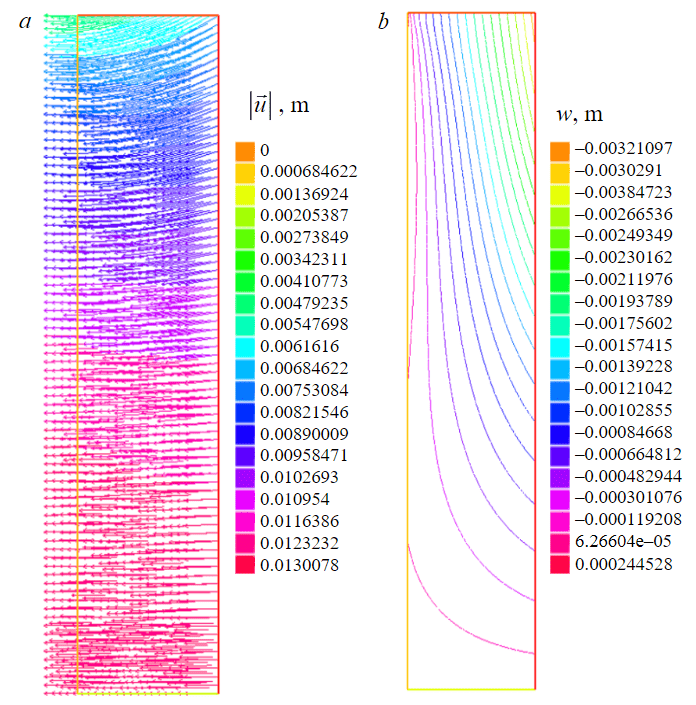
Fig.4. Numerical solution of the problem of the stress-strain state in the FW for the second calculation scheme: vector field of total displacements (a) and contour lines of vertical displacements (b) in the vertical section of the FW 5 m high
Analysis of FW deformation (Fig.4) indicates a significant difference in magnitude between vertical and radial displacements, with vertical displacements being approximately an order of magnitude lower than radial ones. Radial displacements exhibit a notable dependency on the vertical coordinate, evident in both the first design scheme (Fig.5, a) and the second (Fig.5, b). This highlights the pivotal role of shear stress τrz ≈ G∂u/∂z in determining the stress-strain state within the FW and the evolution of the plastic deformation zone. While vertical movements display minor variations in height, localized deviations occur primarily at the external and internal boundaries of the FW. Consequently, the first term in equation (16) is commonly disregarded [26], then:
where C(z) – represents an unknown function of the z coordinate.
Equation (18) provides an approximate depiction, as at the internal boundary of the FW, the tangential stress τrz ought to vanish. At the outer boundary, τrz may either equate to zero or deviate from zero, contingent upon the accepted condition of contact between unfrozen soils and FW in the chosen computational scheme. In the present scenario, it is presumed that the contact is 'sliding', thus necessitating τrz to vanish at the outer boundary as well.
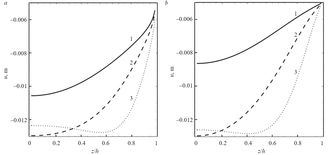
Fig.5. Dependence of radial displacement on the vertical coordinate at the inner boundary of the FW for the first (a) and second (b) design schemes 1 – h = 2.5 m; 2 – h = 5 m; 3 – h =10 m
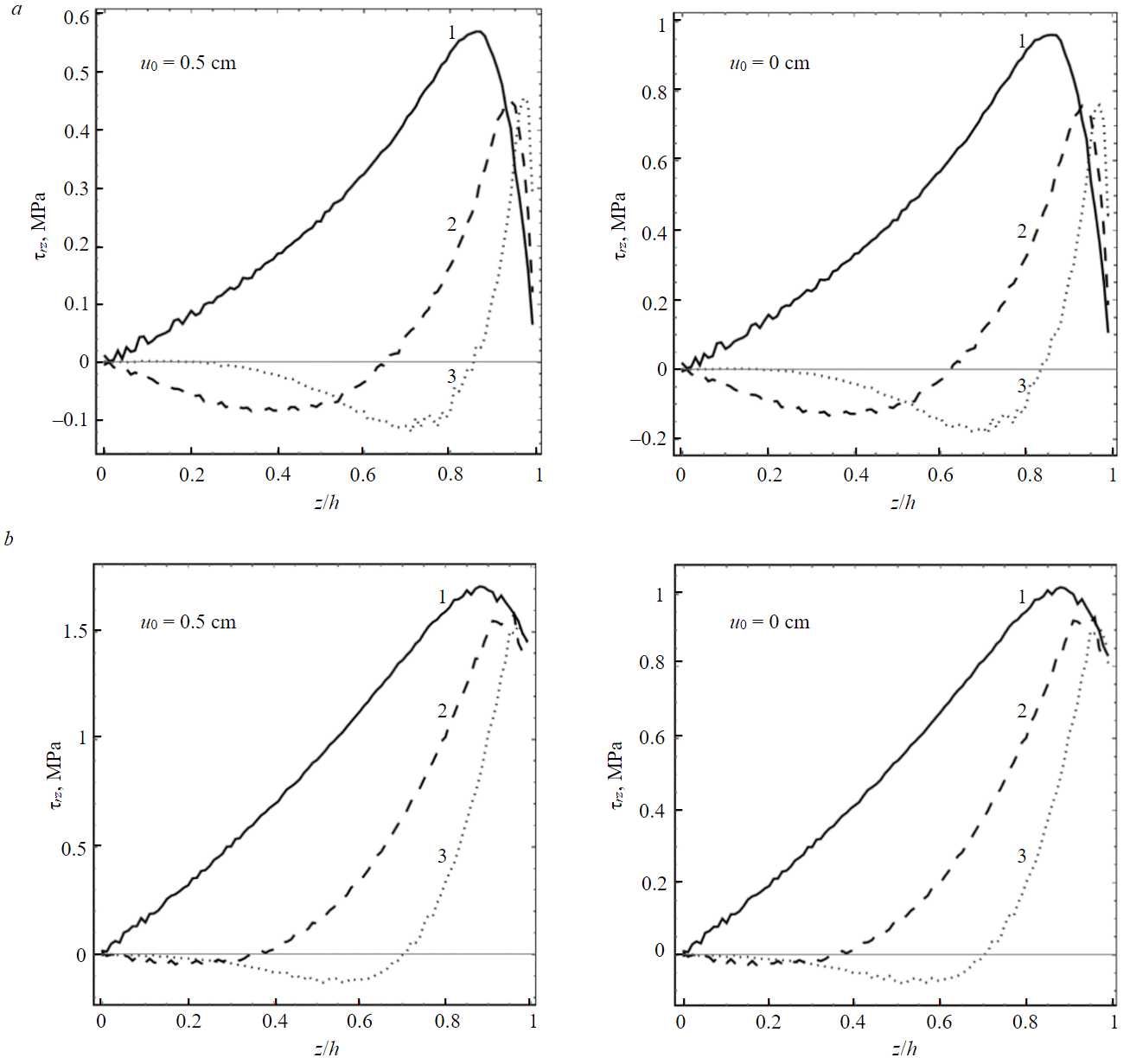
Fig.6. Dependence of the shear stress τrz on the vertical coordinate at different stope heights in the median radial section of the FW, design schemes with fixed vertical load (a) and fixed displacements (b) at the upper base
The issue arises concerning the definition of the function C(z). Results from numerical simulations, particularly in cases involving a specified vertical load at the upper boundary of the FW (Fig.6, a), demonstrate that the dependence τrz(z) exhibits a complex nonlinear and nonmonotonic character. At the upper and lower boundaries of the FW, the tangential stress vanishes, while within the FW, the function τrz(z) may exhibit one or two local extrema. Notably, this function is significantly influenced by the displacement u0of the inner wall of the FW at the upper base of the FW cylinder.
The tangential stress gradient ∂τrz/∂z, as per formula (15), alternates in sign, a characteristic particularly evident in the design scheme involving a vertical load (Fig.6). Near the upper base of the FW (z = h), it assumes a negative value, peaking in modulus. Between z = 0.85-0.97h, the gradient reaches zero, and further decreases in z result in a positive value over a certain segment, diminishing in absolute magnitude as the curve τrz(z) flattens. The presence of a second extremum, if any, occurs on a flat section of the curve and thus garners less interest. A similar trend is observed in the calculation scheme with fixed displacements at the upper base (Fig.6, b), with the dependence of shear stress on the vertical coordinate z approaching linearity for lower penetration heights.
In [27], to derive the FW thickness formula based on the creep criterion, a linear dependence of shear stress on the vertical coordinate τrz(z) = Az + B was assumed. This linear form offers a straightforward approach, necessitating minimal additional conditions for determining the unknown coefficients A and B. Moreover, considering this dependence, the derivative τrz(z) with respect to 𝑧 remains constant, and the parameter z is eliminated from equation (15), rendering it convenient for theoretical analysis.
Under boundary conditions at the lower and upper bases of the FW
the linear function of tangential stresses on z can be represented in the form
The coefficient for z in the linear dependence τrz(z) of formula (21) was derived based on the condition of a linear relationship τrz, u*(r) in equation (20) with modulus G. In this context, the dimensional geometric parameter (ah)–1 is chosen to ensure the correct asymptotic behavior of the solution for the problem at hand for small values of h.
Expression (21) is well aligned with condition (18), which establishes the dependence of shear stress on the radial coordinate. By incorporating formula (21), equation (15) can be expressed as follows:
In [27, 37] equation (22) was solved by substituting the expression for σθ from the Mohr – Coulomb criterion (8) into it. The resulting differential equation featured a single unknown function σr and could be analytically solved, considering the conditions (9) at the boundaries of the computational domain. However, with the consideration of non-zero shear stress τrz, the axial stress components in the general scenario will no longer represent the principal stresses. Furthermore, in the vicinity of the upper base of the FW, the angular stress assumes the role of the second principal stress and is thus not encompassed in the overarching Mohr – Coulomb criterion, which is articulated as follows:
In contrast to the upper base region of the FW cylinder, where a simple analytical solution is lacking, the lower base area exhibits substantially lower shear stress compared to other stress tensor components, with the angular stress assuming the role of the first principal stress σ1. Under these circumstances, equation (22) admits an analytical solution for the stress field, subject to conditions of the limiting stress state, wherein the Mohr – Coulomb law is upheld across the entirety of the soil volume:
In formula (25), the dependence (17) was utilized as the displacement ua. Upon substituting equalities (23) and (22), the principal stresses are expressed as follows: σ1 = σθ, σ3 = σr. Here, the coefficient ξ ≥ 1 serves as an adjustment to consider the influence of plastic deformations. Its value can be determined from tabulated data or set to one for an upper estimate of the required FW thickness. If we set r = b and σr = Р in equation (24), and derive the value E = b – a from the resulting expression, we obtain the following formula:
Formula (26) holds true for the FW region where tangential stresses are lower than the normal components of the stress tensor, encompassing the entire volume of the FW, except for the upper base area. The application of this formula is warranted only if the upper base area is not the most critical concerning maximum stresses in the unsupported section of the FW.
The emergence of a plastic stress zone in an FW with finite advance height primarily occurs near the upper base, close to the inner boundary of the FW. This is because radial stresses in this area are minimal (due to the condition of no load at the boundary r = a), while vertical stresses are maximal, reaching approximately q. Consequently, the initiation and progression of a plastic deformation zone take place throughout the entire volume of the FW, extending to the region of the lower base. In this zone, the limit equilibrium condition is attained earlier as the plastic deformation propagates through the FW's entire thickness. However, near the upper base and the outer boundary of the FW, the plastic deformation zone may not develop due to peculiarities in setting the boundary conditions, which essentially determine the stress field: tangential stresses will be negligible, radial stresses will be approximately P, and vertical stresses will be around q.
This can be demonstrated by considering the ratio of P to q, derived from A.N.Dinnik's classical formula for the lateral thrust pressure of soils [38], along with the given hydrostatic pressure from groundwater in the pore space of soils:
where ν represents the Poisson’s ratio of unfrozen soils surrounding the FW, and Ph – signifies the hydrostatic pressure of pore water, Pa.
If we substitute equation (27) as the third principal stress into the Mohr – Coulomb law (23), and considering σ1 = q, the transformation yields the inequality:
For the soil types considered in the table and their corresponding depths, inequality (28) holds true over a wide range of possible values for ν, typically within the range of [0.35; 0.5], even when Ph equals zero.
For large values of the advance height h, formula (26) adopts the form of the classical formula (1). Therefore, it is crucial to determine the critical value of h at which the additional term (26) becomes negligible. In other words, to calculate the thickness of the FW assuming an unrestricted advance height, formula (1) can be employed.
Through a series of numerical computations, the dependence of FW thickness using formula (26) on h was determined for four distinct types of soils outlined in the table. Assuming ξ = 1 and ν = 0.35, the numerically calculated E(h) curves are depicted in Fig.7.
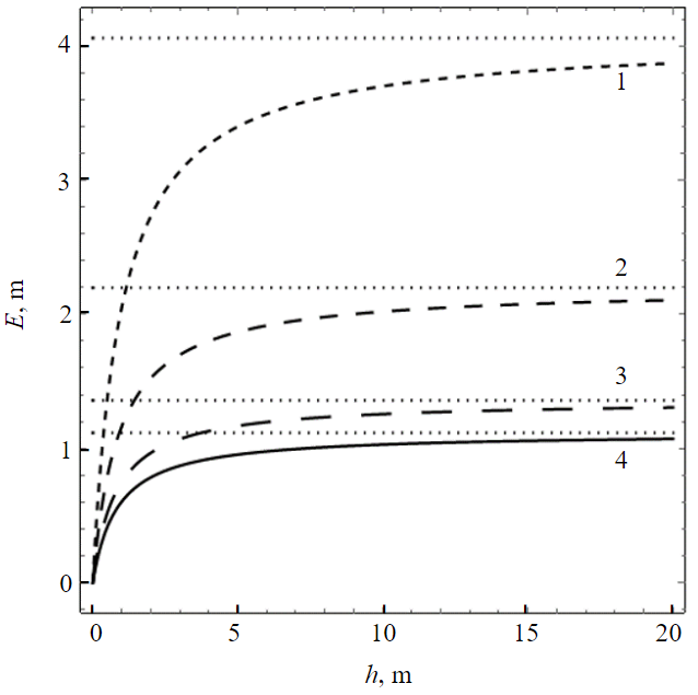
Fig.7. Dependence of FW thickness E on the advance height h for the considered soil types 1 – silt; 2 – sandy loam; 3 – chalk; 4 – clay
In Fig.7, the dots represent horizontal asymptotes, derived from calculating the FW thickness using formula (1), corresponding to a scenario where h approaches infinity. From Fig.7, it is evident that even at an advance height of 9 m, the discrepancies between formulas (1) and (26) are less than 10 %. However, with an entry height of 4 m, these differences range from 16 to 20 %.
A similar analytical methodology was employed in [8], where the determination of ua in expression (22) was based not on solving the elastic problem (15), but on the maximum permissible displacements of the inner wall of the FW. This approach resulted in a critical advance height several times higher than the findings of this study, suggesting that the proposed method serves as a refinement of previous investigations.
The peculiarity of the proposed formula (26) for calculating the required FW thickness lies in the fact that as h approaches infinity, the thickness of the FW cylinder in formula (26) converges to an asymptote. Conversely, in the classical formulas of S.S.Vyalov for FW thickness according to the strength criteria (3), as well as limit deformations [20, 27], such asymptotic behavior is absent, and the FW thickness itself tends to infinity as h→+∞. This discrepancy arises because S.S.Vyalov’s formula for FW thickness according to the creep criterion was derived for small stope heights and is not applicable for large advance heights, as indicated by the analyses in articles [20] and [27]. The presence of an asymptote as h approaches infinity is logical when employing the assumption of the limiting equilibrium state of the structure and frozen soils, as in this study. However, this was not considered when deriving the formula for calculating the minimum FW thickness based on the creep criterion in [27].
It is intriguing to explore another limiting case, where h tends to zero. In the scenario of small h, the proposed formula (26) can be approximated as a linear function of h. To achieve this, we expand formula (26) into a Taylor series around h = 0, retaining terms up to and including linear:
This expression yields a qualitatively similar dependence E = f (P, h) on the main problem parameters, albeit with several nuanced differences. If we assume that formula (3) provides an accurate prediction for the FW thickness at small h, then utilizing equation (29), we can determine the coefficient ξ such that the equality of FW thicknesses calculated using formulas (29) and (3) is upheld. Consequently, the following expressions are derived:
The resulting formula (30) for calculating the FW thickness was derived considering Λ¯ = 2Ctan(π/4 + φ/2) = σc [24]. It aligns well with formulas (1) and (3) by S.S.Vyalov for both limiting cases of entry height. Moreover, the advantage of formula (30) over equation (26) lies in the absence of additional coefficients characterizing the physical and mechanical properties of frozen soils, ν, and the nature of plastic deformations, ξ. The coefficient ξ in equation (30) typically exhibits a significantly higher value compared to the results obtained from numerical calculations in the table.
Conclusion
The principal outcome of this study is the derivation of a formula for calculating the required thickness of the frozen wall, considering the finite advance height and adhering to the widely accepted Mohr – Coulomb strength criterion for frozen soils. The consideration of finite advance height holds particular significance in the context of constructing mine shafts in potash mines utilizing artificial freezing and a combined technological approach for sinking and lining [39, 40].
Drawing upon prior investigations into the impact of stress-strain conditions of surrounding unfrozen soils and the non-uniformity of the temperature field on the required thickness of the frozen wall [13, 14, 28], the formula can be extended to accommodate these factors. This area constitutes a subject for further exploration by the authors.
The strength characteristics of frozen soils, as discussed in this paper, typically wield paramount importance for relatively shallow soil layers (up to depths of 100-150 m). However, for deeper soil layers, alongside strength considerations, it becomes imperative to account for creep behavior and investigate the limiting deformed state of the soils. Hence, static (geomechanical) analysis should encompass the determination of the frozen wall thickness based on the creep criterion, employing methodologies and formulas outlined in [27], for instance.
References
- Shuplik M.N. Analysis of special methods of construction in urban conditions. Mining Informational and Analytical Bulletin. 2014. N S1, p. 523-546 (in Russian).
- Ehringhausen N., Schweppe G., te Kamp L., Akinshin I. Numerical Simulation of Shaft Sinking Using the Artificial Freezing Method. Mining Report. 2021. Vol. 157. Iss. 4, p. 350-359.
- Baryah A.A., Evseev A.V. Closure of potash and salt mines: Review and analysis of the problem. Mining Informational and Analytical Bulletin. 2019. N 9, p. 5-29 (in Russian). DOI: 10.25018/0236-1493-2019-09-0-5-29
- Olkhovikov Yu.P. Lining of Underground Workings in Potash and Salt Mines. Moscow: Nedra, 1984, p. 238 (in Russian).
- Semin M.A., Brovka G.P., Pugin A.V. et al. Effects of temperature field nonuniformity on strength of frozen wall in mine shafts. Mining Informational and Analytical Bulletin. 2021. N 9, p. 79-93 (in Russian). DOI: 10.25018/0236_1493_2021_9_0_79
- Kazikaev D.M., Sergeev S.V. Diagnostics and monitoring of the stress state of vertical shaft lining. Moscow: Gornaya kniga, 2011, p. 244 (in Russian).
- Song Zhang, Zurun Yue, Xiangzhong Lu et al. Model test and numerical simulation of foundation pit constructions using the combined artificial ground freezing method. Cold Regions Science and Technology. 2023. Vol. 205. N 103700. DOI: 10.1016/j.coldregions.2022.103700
- Semin M.A., Levin L.Yu. Methods for calculating artificial ground freezing during the construction of mine shafts. Moscow: Nauchnyi mir, 2021, p. 152 (in Russian).
- Kovrizhnykh A.M., Usoltseva O.M., Kovrizhnykh S.A. et al. Investigation of Strength of Anisotropic Rocks under Axial Compression and Lateral Pressure. Journal of Mining Science. 2017. Vol. 53. N 5, p. 831-836. DOI: 10.1134/S1062739117052849
- Levin L.Yu., Semin M.A., Plekhov O.A. Comparative analysis of existing methods for calculating frozen wall thickness for mine shafts under construction. Bulletin of PNRPU. Construction and Architecture. 2018. Vol. 9. N 4, p. 93-103 (in Russian). DOI: 10.15593/2224-9826/2018.4.09
- Chenchen Hu, Zhijiang Yang, Tao Han, Weihao Yang. Calculation Method of the Design Thickness of a Frozen Wall with Its Inner Edge Radially Incompletely Unloaded. Applied Sciences. 2023. Vol. 13. Iss. 23. N 12650. DOI: 10.3390/app132312650
- Sanger F.J., Sayles F.H. Thermal and rheological computations for artificially frozen ground construction. Engineering Geology. 1979. Vol. 13. Iss. 1-4, p. 311-337. DOI: 10.1016/0013-7952(79)90040-1
- Yang Wei-hao, Du Zi-bo, Yang Zhi-jiang, Bo Dong-liang. Plastic design theory of frozen soil wall based on interaction between frozen soil wall and surrounding rock. Chinese Journal of Geotechnical Engineering. 2013. Vol. 35. Iss. 10, p. 1857-1862.
- Bo Zhang, Weihao Yang, Baosheng Wang. Plastic Design Theory of Frozen Wall Thickness in an Ultradeep Soil Layer Considering Large Deformation Characteristics. Mathematical Problems in Engineering. 2018. Vol. 2018. N 8513413. DOI: 10.1155/2018/8513413
- Akhtar S., Li B. Numerical Analysis of Pipeline Uplift Resistance in Frozen Clay Soil Considering Hybrid Tensile-Shear Yield Behaviors. International Journal of Geosynthetics and Ground Engineering. 2020. Vol. 6. Iss. 4. N 47. DOI: 10.1007/s40891-020-00228-9
- Xingyan Liu, Enlong Liu. Application of new twin-shear unified strength criterion to frozen soil. Cold Regions Science and Technology. 2019. Vol. 167. N 102857. DOI: 10.1016/j.coldregions.2019.102857
- Jilin Qi, Wei Ma. A new criterion for strength of frozen sand under quick triaxial compression considering effect of confining pressure. Acta Geotechnica. 2007. Vol. 2. Iss. 3, p. 221-226. DOI: 10.1007/s11440-007-0034-z
- Pouragha M., Jebeli M., Glade R. Failure of partially saturated frozen soils: A micromechanical analysis. Cold Regions Science and Technology. 2023. Vol. 210. N 103842. DOI: 10.1016/j.coldregions.2023.103842
- Dongwei Li, Xin Yang, Junhao Chen. A study of Triaxial creep test and yield criterion of artificial frozen soil under unloading stress paths. Cold Regions Science and Technology. 2017. Vol. 141, p. 163-170.
- Kostina A., Zhelnin M., Plekhov O. et al. An Applicability of Vyalov’s equations to ice wall strength estimation. Frattura ed Integrità Strutturale. 2020. Vol. 14 (53), p. 394-405. DOI: 10.3221/igf-esis.53.30
- Feng Hou, Yuanming Lai, Enlong Liu et al. A creep constitutive model for frozen soils with different contents of coarse grains. Cold Regions Science and Technology. 2018. Vol. 145, p. 119-126. DOI: 10.1016/j.coldregions.2017.10.013
- Li Dong-Wei, Fan Ju-Hong, Wang Ren-He. Research on visco-elastic-plastic creep model of artificially frozen soil under high confining pressures. Cold Regions Science and Technology. 2011. Vol. 65. Iss. 2, p. 219-225. DOI: 10.1016/j.coldregions.2010.08.006
- Nishimura S., Gens A., Oliverlla S., Jardine R.J. THM-coupled finite element analysis of frozen soil: formulation and application. Géotechnique. 2009. Vol. 59. Iss. 3, p. 159-171. DOI: 10.1680/geot.2009.59.3.159
- Kostina A., Zhelnin M., Plekhov O. et al. Creep behavior of ice-soil retaining structure during shaft sinking. Procedia Structural Integrity. 2018. Vol. 13, p. 1273-1278. DOI: 10.1016/j.prostr.2018.12.260
- Vyalov S.S., Zaretsky Yu.K., Gorodetsky S.E. Stability of Mine Workings in Frozen Soils. Developments in Geotechnical Engineering. 1979. Vol. 26, p. 339-351. DOI: 10.1016/B978-0-444-41782-4.50031-2
- Zhelnin M., Kostina A., Plekhov O. et al. Numerical analysis of application limits of Vyalov’s formula for an ice-soil wall thickness. Frattura ed Integrità Strutturale. 2019. Vol. 13 (49), p. 156-166. DOI: 10.3221/IGF-ESIS.49.17
- Vyalov S.S. Strength and creep of frozen soils and calculations of frozen wall. Moscow: Izd-vo Akademii nauk SSSR, 1962, p. 254 (in Russian).
- Semin M. Calculation of frozen wall thickness considering the non-uniform distribution of the strength properties. Procedia Structural Integrity. 2021. Vol. 32, p. 180-186. DOI: 10.1016/j.prostr.2021.09.026
- Bekele Y.W., Kyokawa H., Kvarving A.M. et al. Isogeometric analysis of THM coupled processes in ground freezing. Computers and Geotechnics. 2017. Vol. 88, p. 129-145. DOI: 10.1016/j.compgeo.2017.02.020
- Tounsi H., Rouabhi A., Jahangir E. Thermo-hydro-mechanical modeling of artificial ground freezing taking into account the salinity of the saturating fluid. Computers and Geotechnics. 2020. Vol. 119. N 103382. DOI: 10.1016/j.compgeo.2019.103382
- Vallier F., Mitani Y., Boulon M. et al. A Shear Model Accounting Scale Effect in Rock Joints Behavior. Rock Mechanics and Rock Engineering. 2010. Vol. 43. Iss. 5, p. 581-595. DOI: 10.1007/s00603-009-0074-9
- Huabei Liu. Unified sand modeling using associated or non-associated flow rule. Mechanics Research Communications. 2013. Vol. 50, p. 63-70. DOI: 10.1016/j.mechrescom.2013.04.003
- Shi Z., Buscarnera G., Finno R.J. Simulation of cyclic strength degradation of natural clays via bounding surface model with hybrid flow rule. International Journal for Numerical and Analytical Methods in Geomechanics. 2018. Vol. 42. Iss. 14, p. 1719-1740. DOI: 10.1002/nag.2813
- Karev V.I., Kovalenko Y.F., Ustinov K.B. Modeling Deformation and Failure of Anisotropic Rocks nearby a Horizontal Well. Journal of Mining Science. 2017. Vol. 53. N 3, p. 425-433. DOI: 10.1134/S1062739117032319
- Bezmaternykh A.V., Ofrikhter V.G. The phenomenon of dilatancy and its impact on the nature of deformation of soil under load. Master’s Journal. 2017. N 2, p. 85-90 (in Russian).
- Junchen Zhou, Keyong Wang, Peichao Li. Hybrid fundamental solution based finite element method for axisymmetric potential problems with arbitrary boundary conditions. Computers & Structures. 2019. Vol. 212, p. 72-85. DOI: 10.1016/j.compstruc.2018.10.012
- Nasonov I.D., Shuplik M.N. Regularities of formation of frozen walls during the construction of mine shafts. Moscow: Nedra, 1976, p. 237 (in Russian).
- Olovyanny A.G. Lateral earth pressure in rock mass. Journal of Mining Institute. 2010. Vol. 185, p. 141-147 (in Russian).
- Mishedchenko A.A. On the necessity to use a cast-iron lining innovative design during construction of vertical mine shafts with a depth of more than 500 m. Mine Surveying and Subsurface Use. 2017. N 4 (90), p. 37-39 (in Russian).
- Semin M., Golovatyi I., Levin L., Pugin A. Enhancing efficiency in the control of artificial ground freezing for shaft construction: A case study of the Darasinsky potash mine. Cleaner Engineering and Technology. 2024. Vol. 18. N 100710. DOI: 10.1016/j.clet.2023.100710