Development of a pump-ejector system for SWAG injection into reservoir using associated petroleum gas from the annulus space of production wells
- 1 — Ph.D., Dr.Sci. Professor RUDN University
- 2 — Postgraduate Student RUDN University ▪ Orcid

Abstract
Implementation of SWAG technology by means of water-gas mixtures is a promising method of enhanced oil recovery. The use of associated petroleum gas as a gas component in the water-gas mixture allows to significantly reduce the amount of irrationally consumed gas and carbon footprint. Relevant task is to choose a simple, reliable and convenient equipment that can operate under rapidly changing operating conditions. Such equipment are pump-ejector systems. In order to create water-gas mixture it is proposed to use associated gas from the annulus space. This solution will reduce the pressure in the annulus space of the production well, prevent supply disruption and failure of well equipment. The paper presents a principal technological scheme of the pump-ejector system, taking into account the withdrawal of gas from the annulus space of several production wells. The layout of the proposed system enables more efficient implementation of the proposed technology, which expands the area of its application. Experimental investigations of pressure and energy characteristics of the ejector have been carried out. Analysis of the obtained data showed that it was possible to increase the value of maximum efficiency. The possibility of adapting the system in a wide range of changes in operating parameters has been established. Recommendations on selection of a booster pump depending on the values of working pressure and gas content are given.
None
Introduction
The average oil recovery factor (ORF) in Russia is about 36 % [1], and there is a negative trend for this value. According to the records of the Central Commission for Mineral Resources Development, the average oil recovery factor in Russia is 38 %. At the same time, according to the data [2], the ORF value of 38 % is related to the traditional reserves, excluding hard-to-recover reserves (HRR). As a whole for all reserves, ORF value of 30-32 % seems to be realistic. That is why enhanced oil recovery (EOR) methods are becoming increasingly important. The basis for their introduction [3] is hydrodynamic development systems, in which physical, chemical, microbiological, water-gas methods work efficiently.
A systematization of EOR projects around the world [4] shows that gas EOR methods currently predominate. Based on a conservative estimate, gas EOR projects account for 47 %, thermal projects for 44 %, chemical and other technologies for 9 %. According to the most radical estimation, the share of gas EOR projects is estimated at 56 %, whereas the share of thermal projects is 32-41 %.
At present technologies of water-gas methods are being actively developed. Combined injection of water and gas into the reservoir in the form of fine-dispersed water-gas mixtures is the most perspective [5, 6]. For water-gas methods, the following is used associated petroleum gas (APG), natural gas, nitrogen, carbon dioxide, flue gases. The problems of SWAG realization with application of APG taken from the annulus space of the production wells with the help of pump-ejector systems are considered in this work.
Statement of the problem
During mechanized pumping operation of production oil wells, free gas at the pump inlet partially separates from the liquid due to natural or artificial (when a gas separator is installed at the pump inlet) separation and enters the annulus space. As APG accumulates in the annulus space, the pressure in it gradually increases, which must be taken into account when calculating the bottom hole pressure based on the results of hydrodynamic investigations [7]. The increase of annulus gas pressure during the operation of wells increases the bottomhole pressure, the depression of the pay zone decreases and the oil production drops. Although the method of gas bypass from the annulus space into the line through the check valve installed on the wellhead equipment is widely used at the fields, this does not solve the problem at high line pressures, which can reach 3-4 MPa in the oil and gas gathering systems at the remote sections. The annulus pressure is higher than the line pressure by the amount of hydraulic loss in the check valve. At high line pressure, an increase in annulus pressure due to gas accumulation leads to a pushback and reduction of the dynamic level down to the pump inlet, which causes stall and premature equipment failures.
Insufficient liquid level above the pump leads to significant complications in the operation of well pumping units and reduces their efficiency [8]. In [9] the influence of gas on parameters of submersible centrifugal pumps was shown. In order to operate wells with high gas-oil ratio, it was necessary to develop multiphase rod downhole pump [10]. The article [11] gives recommendations to improve well operation with electric submersible pumps at high values of gas-oil ratio and content of asphaltene-resin-paraffin components in oil. In [12] actual measurements of annulus pressure growth are presented and the formula for calculating accumulation time is derived.
An important point, based on the analysis of field data, should be noted. In the development of oil fields with waterflooding, the gas-oil ratio increases significantly [13-15]. It occurs due to mass conversion and transfer of APG components (methane-ethane-propane) from oil to water [16-18]. Such an increase of gas-oil ratio undoubtedly contributes to increase of negative influence of gas in the intake of submersible centrifugal and rod pumps, gas accumulation and pressure increase in annulus space of production wells.
The development of technologies for reducing the annulus pressure to the optimum values is one of the urgent tasks for increasing the efficiency of mechanized oil production. There are various methods for its solution: annulus gas bypass into the tubing through the gas lift valve [19], use of ejector [20], annulus gas suction by the compressor into the line [21, 22].
The paper [23] presents methodology for calculation of dynamics for annulus gas pressure growth and decrease of liquid level in well in time, period of gas accumulation. This work also developed mathematical model taking into account operating conditions, application of compressors for gas suction driven by rod pumping unit, showed expediency of annulus pressure reduction to the level of 0.4-0.6 MPa. However, it is not recommended to reduce the bottomhole pressure below these values.
At the same time, there are many objects at the fields with high annulus pressure where compressors or other devices are limited in their ability to inject gas into the outlet pipelines due to critical line pressure. When directing the annulus gas into the oil pipeline, the pressure increases due to increased hydraulic resistance and pipe rupture can occur. The inevitable increase in pressure in the oil pipelines will result in a reduction of pumping efficiency as well as an increase in power consumption. The same objects with high annulus pressure have low ORF values and development rates.
For these objects, there is another option to reduce annulus pressures without increasing line pressure, which, in addition to improving well performance and flow rates, also increases ORF: SWAG technology using APG sucked out of the annulus space of the production wells.
It is possible to use APG from the annulus space of production wells by sucking it out with an ejector and directing it together with water as a mixture to the injection well, i.e. to realize the SWAG technology. The data presented in [24] show the importance of the mentioned problem for Tatarstan fields. However, the mentioned solution is applicable only for low pressures of water-gas mixture injection that can be provided by the ejector. Such conditions are very rare at the fields, so the solution [24] could not be implemented in practice.
In order to increase injection pressure in [25], the technology of using surface jet devices directly at well clusters as a part of pump-ejector systems for gas suction from annulus space of production wells and directing it together with water to injection wells is proposed. At the same time, the existing infrastructure of field equipment at a well cluster (water line, wellhead equipment of production and injection wells) is used. In addition, an ejector, a gas line for supplying gas from the annulus space and directing it to the ejector receiving chamber, a booster multistage vane pump, a reagent dosing unit, as well as control and measuring equipment are installed. Reagents (hydrate inhibitors and foam-forming surfactants) are fed into the water line by means of the reagent dosing unit. In the ejector's flow section, the two streams mix to form a fine-dispersed water-gas mixture with high foaming properties. The resulting mixture is injected after the ejector into the wells by a booster pump. The system presented in [25], due to some shortcomings in terms of functionality and application, has not been implemented.
At present, almost all oil companies have an acute problem of increasing the ORF, and at many objects there is a problem of high annulus gas pressure. The development of a SWAG technology technology that simultaneously addresses the problems of reducing the annulus pressure and increasing the well flow rates and enhancing oil recovery is highly relevant.
The aim of this work is to develop a unit with enhanced functionality to extend the application of SWAG technology in the use of annulus APG. In order to achieve this goal, bench investigations of ejectors have been carried out.
Methodology
The technological scheme of the pump-ejector system for SWAG technology using associated petroleum gas from the annulus space of production wells was developed taking into account the experience of introducing the SWAG unit at the Samodurovskoye field [26]. When deve-loping the new technical solution, results of works [27-29] on APG utilization, research of jet devices [25, 30, 31], water desalting with the help of jet pumps [32], equipment for sucking out the annulus gas [12], SWAG technology methods [33-35] were taken into account.
The developed technical solution is aimed at increasing the efficiency of oil production by increasing the flow rate of associated petroleum gas directed to create a water-gas mixture, reducing the pressure in the oil gathering collector, and implementing efficient unsteady wave operation modes.
Scheme of a pump-ejector system for SWAG technology is shown in Fig.1. The injection is carried out as follows. The ejector, in the nozzle of which water is injected, sucks associated petroleum gas from annulus space of oil production wells. When sucking the gas, the value of annulus pressure is reduced. The water-gas mixture is created, dispersed, the pressure is increased by the booster pump, and then the mixture is injected into the reservoir. Dosing of chemicals (foaming agents, inhibitors etc.) is also carried out. The increase of gas flow rate directed to SWAG technology and gas content of water-gas mixture is performed by ejector suction of associated petroleum gas separated by separator on the surface from water-oil-gas mixture pumped by submersible pump units.
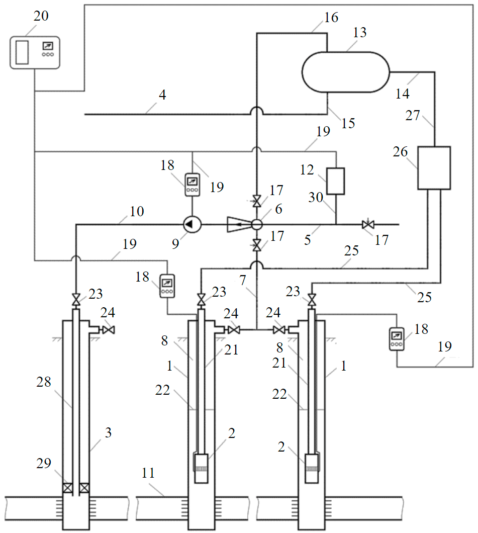
Fig.1. Principle scheme of a pump-ejector system 1 – oil production wells of the cluster; 2 – submersible pump units; 3 – injection well; 4 – oil-gathering collector; 5 – water injection line; 6 – ejector; 7 – gas withdrawal line; 8 – annulus; 9 – booster pump; 10 – water-gas mixture injection line; 11 – formation; 12 – reagent dosing unit; 13 – separator; 14 – water-oil-gas mixture supply line; 15 – liquid outlet line; 16 – gas outlet line; 17 – adjustable gate valves; 18 – variable frequency drives; 19 – power supply cables; 20 – autonomous power plant based on renewable energy sources; 21 – production well tubing; 22 – dynamic levels in production wells; 23 – pipe gate valves; 24 – annulus valves; 25 – discharge lines; 26 – group metering unit; 27 – outlet line; 28 – tubing of injection well; 29 – packer; 30 – tube
Alternate decreasing and increasing of pressure in annulus space is carried out by alternate increasing and decreasing of associated gas suction by ejector from annulus space of production oil wells by controlled valves or by frequency control of booster pump operation. As the frequency increases, the flow rate and pressure of the booster pump increase, resulting in a lower pressure at the ejector outlet and a higher flow rate. Correspondingly, decreasing frequency decreases the flow rate and pressure of the booster pump, resulting in a higher ejector outlet pressure and a lower flow rate. As a booster pump located on the surface, various types of pumping equipment for reservoir pressure maintenance systems can be used, such as horizontal electric centrifugal pump (ECP), vertical ECP in a trench, etc.
For more efficient implementation of unsteady wave operation modes, the receiving chamber of the ejector is alternately connected first to the annulus space of one and then the other oil production well of the cluster. Cycles of wave reduction and restoring of annulus and bottomhole pressure allow increasing oil production flow rates of the wells.
In a system variant, an autonomous renewable energy plant can power the submersible pump and/or booster pump and/or reagent-dosing unit in order to save energy.
The proposed technical solution has the following advantages in comparison with the system [25]. First, there is an increase of oil recovery due to higher flow rate of associated petroleum gas sent to create water-gas mixture when gas is withdrawn not only from annulus space, but also from separator. Second, due to increase of gas withdrawal for SWAG technology, essential decrease of line pressure is reached, as the withdrawn gas does not flow into oil-gas gathering collector and hydraulic loss in it is decreased. Third, wave unsteady modes of annulus and bottomhole pressure decrease and restoring together with decrease of line pressure in oil-gas gathering collector allow increasing well flow rate. Fourth, electrical power is saved through the use of renewable energy sources.
The key element of the proposed system is the ejector. Therefore, in order to assess the possibility of successful implementation of the proposed technical solution, special bench experimental investigations of the jet apparatus were carried out under simulated field conditions.
Experiments were carried out on the test bench [5, 36], the principal scheme of which is shown in Fig.2.
Technical fresh water was used as a liquid phase, and atmospheric air as a gas. As it is known, it is necessary to use technical water and air as reference environments during bench tests of ejectors for APG utilization. This approach provides uniformity of experimental conditions, compatibility of results, facilitates designing of benches and field units, as well as a choice of measuring instruments. At the same time, observance of similarity modes allows extending test results or recalculating parameters to other operating conditions, for example, other values of properties for liquids and gases.
Depending on the pressure, at which the experiments were carried out at the inlet, either air from atmosphere or air from compressor 12 (at pressures at intake up to 0.8-1.0 MPa), or from water-gas separator 9 (at pressures at intake from 0.8 to 5.0 MPa) was supplied to the ejector inlet. In the latter case, the sucked gas circulated along the contour water-gas separator – ejector inlet – ejector outlet – water-gas separator was carried out, and before characterization, the water-gas separator was preliminary charged for necessary gas pressure by means of an ejector or compressors. Since air, although slightly, but is still soluble in water, during the experiments a part of the air was carried away with the water from the water-gas separator 9 to the tank 7 and was emitted there into the atmosphere. Therefore, the bench system provides feeding the water-gas separator from cylinder 11 with compressed air through reducer 10. High-pressure compressor 12 made filling of cylinder 11 up to 15 MPa.
Fluid circulation system of the bench is closed. Operating pressure before ejector nozzle 18 was created by pump 1 and regulated by changing rotation frequency of electric motor shaft 4 by means of frequency converter 5, as well as by means of valve 24.
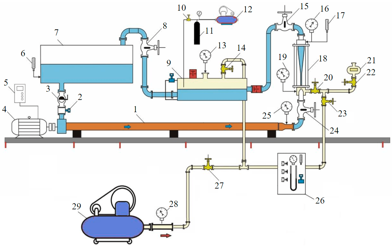
Fig.2. Bench scheme 1 – horizontal multistage pump; 2 – flow rate measuring diaphragm; 3 – ball valve; 4 – electric motor; 5 – frequency converter; 6, 17 – temperature sensors; 7 – tank; 8, 14, 15, 20, 22, 23, 24, 27 – gate valves; 9 – water-gas separator; 10 – reducer; 11 – cylinder; 12, 29 – compressors; 13, 16, 19, 25, 28 – pressure gauges; 18 – ejector; 21 – gas meter; 26 – rheometer for measuring gas flow rate under pressure
The inlet and outlet pressure of the ejector 18 is controlled by valves 20 and 15.
During the experiments, the valve 15 was used to create different backpressures at the ejector 18 outlet, changing its flow rate and pressure, which allowed measuring the parameters and building pressure-flow rate and energy characteristics of the jet apparatus. This method is the most convenient for carrying out bench research and allows taking characteristics of ejectors at different modes by changing hydraulic resistance with throttling the mixture flow at the outlet of jet apparatus. Another advantage of this method is the short time required for stabilization of parameters when changing the mode.
The scheme of the investigated ejector is shown in Fig.3. The diameter of the ejector's rectangular-edged diaphragm nozzle was 3.2 mm and the diameter of cylindrical mixing chamber was 7 mm. The opening angle of the diffuser was 6°. The investigations were carried out with different relative lengths of the mixing chamber Lrel (from 30.6 to 38.3 diameters).
In order to estimate the range of working pressure Рw before the nozzle during implementation of wave modes, in which the proposed pump-ejector system can be operated, and what will be the gas content of mixture at the booster pump inlet, investigations were conducted at different values of Рw and working fluid flow rate Qw. The pressure in the water lines of injection wells at many oilfields are 9-14 MPa. At bench tests, the values of Рw were from 2 to 14 MPa. The pressure in the ejector receiving chamber was maintained equal to 0.4 MPa – minimum expedient value of annulus pressure reduction, proceeding from recommendations [23].
Discussion of the results
The research allowed obtaining pressure and energy characteristics of the ejector at different values of Pw and Lrel. Pressure characteristics are dependencies of pressure ΔPj, created by the jet apparatus, on flow rate of sucked gas Qg.in under conditions of the entry into the ejector's receiving chamber. Energy characteristics are dependencies of ejector efficiency η on Qg.in.
The value ΔPj was found as the difference between the pressure at the outlet of the jet apparatus Pj and pressure in its receiving chamber Pin.
The efficiency of the jet apparatus (ratio of useful power to consumed power) was calculated according to the formula [6]:
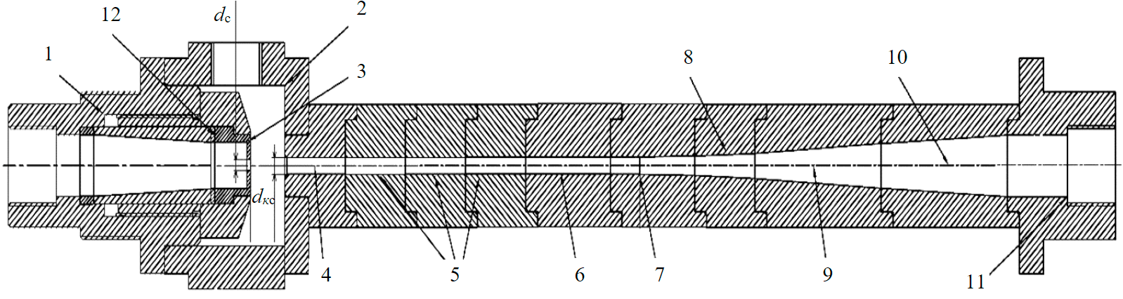
Fig.3. Ejector scheme 1 – inlet; 2 – receiving chamber; 3 – nozzle; 4 – mixing chamber inlet; 5 – mixing chamber intermediate units; 6 – mixing chamber outlet unit; 7 – transition unit from mixing chamber to diffuser; 8 – diffuser inlet unit; 9 – middle part of the diffuser; 10 – outlet part of the diffuser; 11 – diverter; 12 – washer; dn – nozzle diameter; dmx – mixing chamber diameter
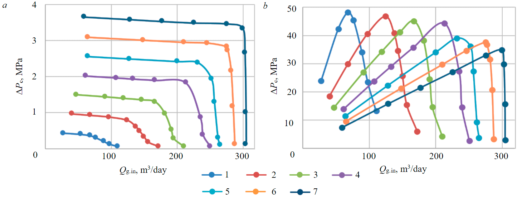
Fig.4. Pressure (а) and energy (b) characteristics of the ejector at different Рw 1 – 2 MPa; 2 – 4; 3 – 6; 4 – 8; 5 – 10; 6 – 12; 7 – 14
Figure 4 shows the pressure and energy characteristics of the ejector with relative length of mixing chamber Lrel = 30.6.
One of the main results of the experiments was the maximum achieved ejector efficiency ηmax = 48.2 % at Рw = 2 MPa, which is the highest value at present. In earlier investigations [36] the maximum efficiency value was 45.9 %.
At working fluid injection pressure Рw = = 2 MPa, as experiments have shown, pressure at ηmax = 48.2 %, developed by ejector in optimum mode ΔPj = 0.36 MPa, is reached. In many cases, this is enough to realize technology of low-pressure APG utilization [27] by its compression with pump-ejector system and directing water-gas mixture after the ejector into the separator, where separation of gas from water takes place. The compressed gas with increased pressure is then dried and sent to into a gas pipeline. Consequently, the practical value of the obtained result is in possibility of its application in various technologies of APG usage, in particular, at utilization of low-pressure APG at end separation stages with increase of gas pressure and directing it into a gas pipeline for the further realization.
This result can be used when promoting [37] the technology of using pump-ejector system for SWAG technology with multistage compression of mixtures, carried out in sequentially placed ejectors, in nozzles of which water is supplied by electric centrifugal pumps. In order to increase efficiency, the pressure and power of the ECP should be changed, decreasing them on ECP at the first stage and increasing them at the second stage. This redistribution will allow more effective operation of the ejector of the second compression stage in the system.
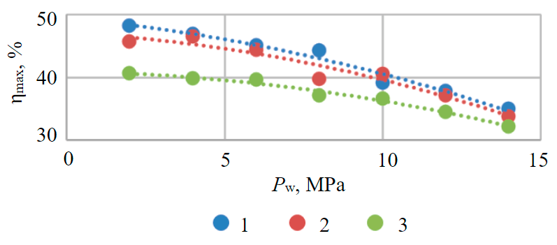
Fig.5. Dependence ηmax on Рw for ejector with relative length of mixing chamber Lrel = 30.6 (1), 33.6 (2) и 38.3 (3)
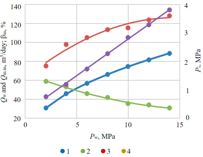
Fig.6. Dependencies of gas content at the booster pump inlet βin (1), water-gas mixture flow rate at the booster pump inlet Qm.in (2), working fluid (water) flow rate Qw (3) and outlet pressure at jet apparatus Pj (4) on Pw for ejector with Lrel = 30.6 at optimum operation modes
As Pw increases, the pressure developed by the ejector and the sucked gas flow rate increase and the operating range expands. However, the efficiency value decreases.
According to the results of experiments it was found that the highest values of efficiency were at the ejector with Lrel = 30.6. The jet apparatus with Lrel = 33.6 had generally slightly lower ηmax values, and the ejector with Lrel = 38.3 had noticeably lower ηmax values. This is clearly shown in Fig.5.
Figure 5 shows the tendency towards reduction of ejector efficiency at operating pressures higher than 2-4 MPa. Investigations [27] have established that the ejector efficiency values ηmax with increase Pw from 0.4 MPa firstly grow, and after Pw = = 1.59 MPa, decrease. The values of ηmax obtained in the conducted experiments are noticeably higher than in the experiments [27]. This can be explained by the fact that in this work the ejector was investigated at pressure value at the inlet into the receiving chamber of 0.4 MPa, while in [27] experiments were conducted at atmospheric pressure at the inlet. As it was found earlier [5], increase of pressure at the inlet to the ejector inlet chamber contributes to increase of efficiency.
Figure 6 shows dependencies of gas content at the booster pump inlet βin, water-gas mixture flow rate at the booster pump inlet Qm.in, working fluid (water) flow rate Qw and pressure at the jet apparatus outlet Pj on Pw for ejector with Lrel = 30.6 at optimum operation modes. They allow estimating influence of Pw value on system parameters.
The pressure of the mixture at the outlet of the jet apparatus Pj is the sum of the pressure at the inlet of the ejector Pr and the pressure it develops ΔPc.
The water-gas mixture flow rate at the booster pump inlet Qm.in was found as the sum of the working fluid (water) flow rate Qw and the gas flow rate sucked by the ejector at the ejector outlet at pressure Pj.
The gas content βin at the booster pump inlet was calculated as the ratio of gas flow rate to mixture flow rate.
The analysis of the results for the conducted experiments has shown that under optimum operating conditions with Pw increase both Qw and mixture flow at the booster pump inlet Qm.in (mixture flow rate after the ejector at Pj pressure) grow, while Pj increases almost linearly, and the mixture gas content at Pj pressure (gas content βin at the booster pump inlet) decreases with increasing Pw.
In the range of working pressures from 2 to 14 MPa, when Pj increases from 0.77 to 3.8 MPa, βin decreases from 58.8 to 30.8 %. Earlier research [33] showed the following. At pumping water-gas mixtures with foaming surfactant the serial multistage ESP can stably operate almost without reduction of average integral parameters (pressure, flow rate and efficiency) up to gas content βin about 35 % with pressures at pump inlet in the range of 3 MPa. Such value of βin in a mixture is provided with pressure at the ejector outlet (at the pump inlet) Рj = 2.83 MPa with Рw = 10 MPa. Therefore, for implementation of the developed technical solution in the range of working pressures higher than 10 MPa it is possible to use serial multistage ECP as a booster pump. At Pw < 10 MPa the booster pump must be equipped with an auxiliary multiphase axial pump. These multiphase pumps can successfully pump gas-liquid mixtures with gas content up to 90 % [38, 39].
Let us consider the change in flow rate of water-gas mixture passing through a multistage centrifugal booster pump when the pressure of the pumped mixture increases along its length. As an example, the following data is taken: working pressure 12 MPa, pressure at pump inlet Pj = 3.29 MPa at gas content βin = 33.8 %, required pressure of pumping mixture at pump unit outlet is 14 MPa. The graph of change in mixture flow rate Qm as a function of pressure growth P along the length of the pump under these conditions is shown in Fig.7.
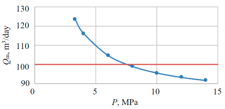
The flow rate at the pump inlet is 123.6 m3/day. Consequently, ECP5-125 pump with a rated flow of 125 m3/day is the most suitable for these conditions. Mixture flow rate decreases as the pressure rises and at P = 8 MPa is 99 m3/day, that exceeds the limits of the working area for the pump ECP5-125 (its left border for this pump corresponds to 100 m3/day). Therefore, it is reasonable to use the ECP5-125 pump stages in this case for increasing the pressure from 3.29 to 8 MPa. It is necessary to install smaller size stages of ECP5-80, i.e., to use conical pump arrangement, which is [40] one of the efficient methods of effeciency increase for multistage pumps operation at pumping gas-liquid mixtures. Figure 7 shows transition boundary from one pump size (ECP5-125) to another (ECP5-80) with dashed line.
Thus, the conducted research has confirmed the possibility of implementing the proposed new technical solution – a pump-ejector system for SWAG using annulus gas in a wide range of working fluid pressure values.
Conclusion
The relevance of developing a technology that allows the use of sucked APG to enhance oil recovery through SWAG technology in addition to solving the problem of high annulus pressure in production wells has been shown.
A new technical solution has been developed for SWAG technology using a pump-ejector system, which has better functionality and wider application scope than previous solutions and enables more efficient oil production, increased oil recovery and higher well flow rates.
Experimental investigations showed a maximum ejector efficiency of 48.2 %, which is the highest value to date. Conducted study with pressure at receiving chamber inlet of 0.4 MPa showed that ejector with relative length of mixing chamber, which is 30.6, has higher values of efficiency.
An increase in operating pressure from 2 to 14 MPa the operating range of the ejector has been found to expand considerably. However, at the same time the efficiency value decreases.
Realization of the proposed pump-ejector system for SWAG technology with the use of annulus gas from production wells in a wide range of working fluid pressure has been confirmed.
During the application of a pump-ejector system at high operating pressure, serial multi-stage centrifugal pumps and conical pumps should be used. At low operating pressure and high gas content, the booster pump should be equipped with an intermittent multiphase axial pump section.
References
- Kryanev D.Yu., Zhdanov S.A. Scientific support for new technologies in the development of oil fields with hard-to-recover reserves. Burenie i neft. 2012. N 8, p. 29-32 (in Russian).
- Kolevatov A.A., Afanasev S.V., Zakenov S.T. et al. Status and prospects of enhanced oil recovery in Russia (Part 1). Express survey. Burenie i neft. 2020. N 12, p. 3-19 (in Russian).
- Muslimov R.Kh. About the new paradigm of academician A.E.Kontorovich – development of the Russian oil and gas complex based on the experience of Tatarstan on the rational development of hydrocarbon resources. Burenie i neft. 2020. N 9, p. 6-14 (in Russian).
- Poddubny Yu.A., Poddubny A.Yu. Methods to Increase Oil Return in the World: Today and Possible Tomorrow. Burenie i neft. 2020. N 12, p. 43-48 (in Russian).
- Drozdov A.N., Drozdov N.A., Gorbyleva Ya.A., Gorelkina E.I. Application of jet apparatus in petroleum engineering. Мoscow: Sputnik+, 2020, p.391 (in Russian).
- Sergeev E., Vinogradov P., Abutalipov U. et al. Experimental Research of Simultaneous Water and Gas Injection Technology into Injection Wells using Mixing Devices. SPE Russian Petroleum Technology Conference, 16-18 May 2017, Moscow, Russia. Society of Petroleum Engineers, 2017. N SPE-187734-MS. DOI: 10.2118/187734-MS
- Abutalipov U.M., Kitabov A.N., Esipov P.K., Ivanov A.V. Analysis of Design And Technological Parameters of Gas-Water Ejector For Associated Gas Utilization. Exposition Oil Gas. 2017. N 4(57), p. 54-58 (in Russian).
- Lekomtsev A.V., Mordvinov V.A., Poplygin V.V., Ponomareva I.N. Efficiency of Electric Submersible Pumps at Extraction of the Gas-Liquid Blends from Wells. Oil Industry. 2012. N 10, p. 132-133 (in Russian).
- Kang Y., Liu Z., Gonzales A., Samuel R. Investigating the Influence of ESP on Wellbore Temperature, Pressure, Annular Pressure Buildup, and Wellbore Integrity. SPE Deepwater Drilling and Completions Conference, 14-15 September 2016, Galveston, Texas, USA. Society of Petroleum Engineers, 2016. N SPE-180299-MS. DOI: 10.2118/180299-MS
- Wang H., Zheng S., YangD. Design and Application of Multiphase Sucker-Rod Pumps in Wells with High Gas-Oil Ratios. SPE Artificial Lift Conference – Latin America and Caribbean, 27-28 May 2015, Salvador, Bahia, Brazil. Society of Petroleum Engineers, 2015. N SPE-173963-MS. DOI: 10.2118/173963-MS
- Rogachev M.K., Aleksandrov A.N. Justification of a comprehensive technology for preventing the formation of asphalt-resin-paraffin deposits during the production of highlyparaffinic oil by electric submersible pumps from multiformation deposits. Journal of Mining Institute. 2021. Vol. 250, p. 596-605. DOI: 10.31897/PMI.2021.4.13
- Mingulov S.G., Mingulov I.S. Techniques for optimization of gas extraction from production wells annulus. International Conference: Actual Issues of Mechanical Engineering (AIME 2020), 27-29 October 2020, Saint Petersburg, Russian Federation. IOP Conference Series: Materials Science and Engineering, 2021. Vol. 1111. N 012037. DOI: 10.1088/1757-899X/1111/1/012037
- Baimukhametov M.K., Gulishov D.S., Mikhaylov V.G. et al. Analysis of causes of gas-oil ratio growth at late stages of oil fields exploration. Bulletin of the Tomsk Polytechnic University. Geo Assets Engineering. 2018. Vol. 329. N 8, p. 104-111 (in Russian).
- Gultyaeva N.A., Toshev E.N. Mass Exchange in the Oil-Gas-Water and Its Effect on the Production of Associated Gas. Oil Industry. 2013. N 10, p. 100-103 (in Russian).
- Gultyaeva N.A., Shylov V.I., Fominyh V.O. Fields development and operation. Territoriya NEFTEGAZ. 2013. N 9, p. 50-57 (in Russian).
- Imashev R.N., Fedorov V.N., Zaripov A.M. On the Gas Factor Change in the Process of Arlanskoye Field Development. Oil Industry. 2016. N 8, p. 122-125 (in Russian).
- Mikhaylov V.G., Ponomarev A.I., Topolnikov A.S. Prediction of Gas Factor Taking Into Account Gas Dissolved In the Water at Late Stages Development of Oil Fields. SOCAR Proceedings. 2017. N 3, p. 41-48 (in Russian). DOI: 10.550/OGP2017030032
- Kordik K.E., Shkandratov V.V., Bortnikov A.E., Leontyev S.A. About Trends in the Oil-Gas Ratio Change in the Process of Exploitation of Lukoil-West Siberia LLC Fields. Oil Industry. 2016. N 8, p. 54-57 (in Russian).
- Liu Y., Li Y., Li X., Tang G. An Approach to Apply the Gas in the Annulus to Assist Pumping Oil in High GOR Wells. Production and Operations Symposium, 31 March – 3 April, 2007, Oklahoma City, Oklahoma, USA. Society of Petroleum Engineers, 2007. SPE-107041-MS. DOI: 10.2118/107041-MS
- Urazakov K.R., Mukhin I.A., Vakhitova R.I. Modelling the characteristics of a jet pump. Elektrotekhnicheskie i informatsionnye kompleksy i sistemy. 2015. Vol. 11. N 4, p. 41-50 (in Russian).
- Isaev A.A., Takhautdinov R.Sh., Malykhin V.I., Sharifullin A.A. Development Of the Automated System for Gas Extraction From Wells. Neft. Gaz. Novatsii. 2017. N 12 (205), p. 65-72 (in Russian).
- Isaev A.A., Takhautdinov R.S., Malykhin V.I., Sharifullin A.A. Oil Production Stimulation by Creating a Vacuum in the Annular Space of the Well. SPE Annual Caspian Technical Conference, 16-18 October 2019, Baku, Azerbaijan. Society of Petroleum Engineers, 2019. N SPE-198401-MS. DOI: 10.2118/198401-MS
- Urazakov K.R., Belozerov V.V., Latypov B.M. Study of the dynamics for gas accumulation in the annulus of production wells. Journal of Mining Institute. 2021. Vol. 250, p. 606-614. DOI: 10.31897/PMI.2021.4.14
- Nurgaliev A.A., Khabibullin L.T. Decision on Use of Associated Gas in Production Oil Wells. Fundamentalnye i prikladnye voprosy gornykh nauk. 2014. Vol. 1. N 1, p. 249-257 (in Russian).
- Drozdov A.N., Drozdov N.A. Prospects of Development of Jet Pump’s Well Operation Technology in Russia. SPE Russian Petroleum Technology Conference 2015. 26-28 October 2015, Moscow, Russia. Society of Petroleum Engineers, 2015. N SPE-176676-MS. DOI: 10.2118/176676-MS
- Drozdov A.N., Drozdov N.A., Bunkin N.F., Kozlov V.A. Study of Suppression of Gas Bubbles Coalescence in the Liquid for Use in Technologies of Oil Production and Associated Gas Utilization. SPE Russian Petroleum Technology Conference 2017. 16-18 October 2017, Moscow, Russia. Society of Petroleum Engineers, 2017. N SPE-187741-MS. DOI: 10.2118/187741-MS
- Drozdov A.N., Gorbyleva Y.A. Improving the Operation of Pump-ejector Systems at Varying Flow Rates of Associated Petroleum Gas. Journal of Mining Institute. 2019. Vol. 238, p. 415-422. DOI: 10.31897/PMI.2019.4.415
- Abutalipov U.M., Kitabov A.N., Esipov P.K., Ivanov A.V. Analysis of Design And Technological Parameters of Gas-Water Ejector For Associated Gas Utilization. Exposition Oil Gas. 2017. N 4(57), p. 54-58 (in Russian).
- Peeran S., Beg N. Innovative, Cost Effective and Simpler Technology to Recover Flare Gas. SPE Middle East Oil & Gas Show and Conference. 8-11 March 2015, Manama, Bahrain. Society of Petroleum Engineers, 2015. N SPE-172745-MS. DOI: 10.2118/172745-MS
- Ainge P. Ejector Technology for Flare Gas Recovery as an Alternative to Rotating Equipment. Abu Dhabi International Petroleum Exhibition & Conference, 11-14 November 2019, Abu Dhabi, UAE. Society of Petroleum Engineers, 2019. N SPE-197909-MS. DOI: 10.2118/197909-MS
- Erenkov O.Y., Lopushanskii I.Y. New Designs of Liquid-Gas Ejectors. Chemical and Petroleum Engineering. 2019. Vol. 55, p. 18-21. DOI: 10.1007/s10556-019-00577-x
- Hosseini A., Noghrehabadi A.R., Behbahani-nejad M. Experimental analysis of a hybrid system including refrigeration cycle and water desalination with jet pump. Journal of Thermal Analysis and Calorimetry. 2021. Vol. 147, p. 1505-1512. DOI: 10.1007/s10973-021-10560-5
- Drozdov A.N. Investigations of the Submersible Pumps Characteristics When Gas-Liquid Mixtures Delivering and Application of the Results for Swag Technologies Development. Oil Industry. 2011. N 9, p. 108-111 (in Russian).
- Agrawal G., Verma V., Gupta S. et al. Novel Approach for Evaluation of Simultaneous Water and Gas Injection Pilot Project in a Western Offshore Field, India. SPE Oil & Gas India Conference and Exhibition. 24-26 November 2015, Mumbai, India. Society of Petroleum Engineers, 2015. N SPE-178122-MS. DOI: 10.2118/178122-MS
- Verbitsky V.S., Igrevsky L.V., Fedorov A.E. et al. Technology Design of Efficient Utilization of Associated Petroleum Gas APG and Possibilities of Its Realization by Pump-Booster and Pump-Ejector Systems. SPE Russian Petroleum Technology Conference and Exhibition 2016. 24-26 October 2016, Moscow, Russia. Society of Petroleum Engineers, 2016. N SPE-181962-MS. DOI: 10.2118/181962-MS
- Krasilnikov I.A. Development of a technique for calculating the characteristics of liquid-gas ejectors for well operation and SWAG technology using pump-ejector systems: Avtoref. dis. … kand. tekhn. nauk. Moscow: RGU nefti i gaza im. I.M.Gubkina, 2010, p. 20 (in Russian).
- Pestov V.M., Yanovsky A.V., Drozdov A.N. Improving the Technology for Water-Gas Mixtures Pumping into the Reservoir. Oil Industry. 2019. N 4, p. 84-86 (in Russian). DOI: 10.24887/0028-2448-2019-4-84-86
- Odintsov A.A. Musinskii A.N. Peshcherenko S.N. Multiphase Axial Pump for Surface Pumping Gas-Liquid Mixture. Oil Industry. 2020. N 2, p. 62-64 (in Russian). DOI: 10.24887/0028-2448-2019-2-62-64
- Peshcherenko M., Perelman O., Rabinovich A., Kaplan A. Increase of ESP efficiency. Multiphase pumps application. Burenie i neft. 2014. № 4. С. 56-60 (in Russian).
- Goridko K.A., Bilalov R.R., Verbitsky V.S. Express Evaluation of The Efficiency of a Tapered Electric Submersible Pump Use When Pumping Gasliquid Mixtures From A Well. Part 1. Oilfield Engineering. 2021. N 2, p. 43-48 (in Russian). DOI: 10.33285/0207-2351-2021-2(626)-43-48