Experimental research on the thermal method of drilling by melting the well in ice mass with simultaneous controlled expansion of its diameter
- 1 — Leading Engineer Saint Petersburg Mining University ▪ Orcid
- 2 — Ph.D. Saint Petersburg Mining University ▪ Orcid

Abstract
During the seasonal work of the 64th Russian Antarctic Expedition in 2018-2019 at the “Vostok” drilling facility named after B.B.Kudryashov (“Vostok” station, Antarctic) specialists of Saint Petersburg Mining University conducted experimental investigations on the process of drilling by melting with simultaneous expansion of wells in the ice mass. A test bench and a full-scale model of a thermohydraulic reamer-drilling tool were developed, manufactured and tested for the research. The first bench tests of the full-scale model proved its efficiency and suitability for experimental drilling with simultaneous expansion of wells in ice mass; its operational capabilities were determined and the drawbacks that will be taken into account in future were found out. The article substantiates the choice of constructive elements for thermohydraulic reamer-drilling tool. It is determined that the technology of full diameter drilling with simultaneous expansion of the well in ice mass can be implemented by combining contact drilling by melting and convective expansion with creation of forced near-bottomhole annular circulation of the heated heat carrier. Dependencies of expansion rate on main technological parameters were determined: active heat power of heating elements in penetrator and circulation system, mechanical drilling rate, pump flow rate. According to the results of investigations, the experimental model of thermohydraulic reamer-drilling tool will be designed and manufactured for testing in conditions of well 5G.
None
Introduction
Detailed study of glaciers and sub-glacial environment is carried out through a combination of direct and remote research methods [1-3]. Direct methods include well drilling with sampling of ice, gas and solid inclusions [4-6]. Drilling technology and appropriate equipment are selected depending on the purpose [7-9]. The analysis of drilling technologies revealed the absence of a single developed and tested method, as well as technical means of drilling the wells in ice with their simultaneous expansion. The experience accumulated by specialists of Saint Petersburg Mining University in drilling with thermal and mechanical methods in ice mass of Antarctic [10-12] made it possible to reach record depths of 2755 [13] and 3769 m in ice wells [14]. There is also a large number of scientific works on thermal cavern formation in ice masses carried out in the 1980s [15]. Successful theoretical and experimental investigations by Russian scientists [2, 16-18] are the scientific groundwork for the development of technology and technical means of ice drilling by melting with simultaneous or subsequent expansion [19].
In practice of well drilling in ice mass, the most widespread are mechanical and thermal methods. Drilling by melting refers to the thermal method in terms of physics of ice destruction process and favourably differs from other known methods [20]. Technical tool based on the thermal method of ice destruction requires the least amount of structural elements, whereas two or more times less volu-me of drilling products is extracted. For example, meltwater or ice in the water-collecting tank of the thermal tool has density 1000 and 920 kg/m3 respectively, and in case of mechanical destruction, the cuttings have density 390-480 kg/m3.
Severe conditions of polar regions and remote location from populated areas impose special requirements to drilling equipment: minimum mass-size characteristics, simplicity and reliability, possibility of application at low temperatures of glaciers (up to −57 °С at “Vostok” station) and environment [21-23]. Thus, standard technological and technical solutions of well drilling in Arctic and Antarctic conditions require significant modernization before starting research work, and the use of load-carrying cable during drilling reduces the weight of drilling equipment by several times.
During the seasonal work of the 64th Russian Antarctic Expedition (RAE) the glacial-drilling team, which includes specialists from Saint Petersburg Mining University and the Arctic and Antarctic Research Institute, performed a number of experimental investigations, planned by the program of drilling operations, at the drilling facility named after B.B.Kudryashov at “Vostok” station in An-tarctic [24]. The aim of the investigations was to assess the operational capability of drilling with simultaneous reaming of wells in the ice mass using a thermohydraulic reamer-drilling tool (TRDT). This will allow to determine the dependence of rate of contact drilling by melting and convective expansion intensity on heating element power, pump flow rate and mass-size characteristics of the drilling tool to verify theoretical research, which describes heat and mass exchange processes occurring at the bottomhole and in the near-bottomhole zone.
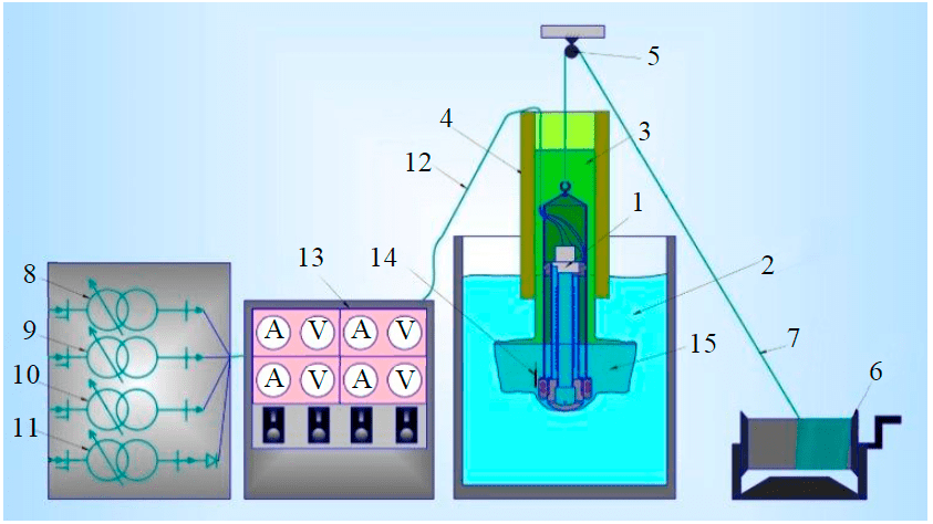
Fig.1. Scheme of an experimental test bench for investigating the drilling by melting with simultaneous well expansion in the ice mass 1 – model of thermohydraulic reamer-drilling tool; 2 – ice block; 3 – fill liquid; 4 – casing pipe; 5 – block; 6 – manual winch; 7 – cable; 8, 9, 10 – AC autotransformers; 11 – Laboratory AC autotransformer with rectifier; 12 – current conductors; 13 – control panel; 14 – thermometer; 15 – meltwater
The results of this research will provide the scientific justification for developing a preliminary design of a thermohydraulic reamer-drilling tool [13], which will be used in the construction of a new well for clean access to the subglacial Lake Vostok to prepare the lower section of the well and penetrate the lake [25-27]. Expanding the lower section of the well followed by penetration of the subglacial lake will reduce the height and rate of lake water rise, which, in turn, will provide long-term access to the subglacial space and prevent active mixing of the fill liquid with water. As the meltwater layer is a buffer layer, the ecological efficiency of the penetration process is increased. According to the declared technology of preparing the lower section of the well with subsequent penetration, it is necessary to drill one meter at the contact with the subglacial lake and simultaneously expand the diameter to two or three times the nominal diameter. By analogy with the 5G well at “Vostok” station, the drilling diameter is 135 mm, which requires enlarging the diameter to 170-305 mm.
As there are currently no cryochambers available at Saint Petersburg Mining University, a test bench was built to trial a model of the developed device at “Vostok” station in Antarctic, where the weather conditions and technical equipment of the dril-ling facility allow full experimental investigations of ice drilling to be carried out.
Methodology
In order to conduct experimental research at the drilling facility named after B.B.Kudryashov of “Vostok” station in Antarctic, a special experimental test bench was developed (Fig.1), which simulates operation of thermohydraulic reamer-drilling tool in the near-bottomhole zone with system of heating elements and forced circulation of heat carrier, capable of performing necessary technological processes with possibility to control main parameters (electric power of heating elements, pump flow rate, rate of downward tool feed). All equipment was placed in the building of drilling facility [17, 28, 29].
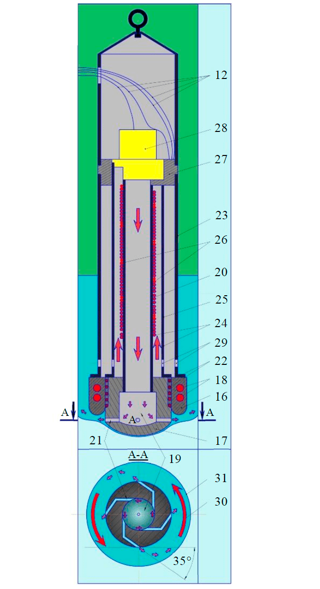
Fig.2. Model scheme of thermohydraulic eamer-drilling tool 16 – crown; 17 – penetrator; 18 – electric ring heaters; 19 – collector; 20 – internal water discharge pipe; 21 – hydraulic channels; 22 – heating element (KNMS NH); 23 – frame; 24 – central double pipe; 25 – outer tube; 26 – heating element (KNMS NH); 27 – pump frame; 28 – pump; 29 – intake windows; 30 – ring circulation; 31 – well walls
The hand winch 6 is rigidly bolted to the base of the drilling facility and is used for lowering, lifting and maintaining the TRDT model 1 in vertical position in the well. The TRDT model 1 is suspended on the cable 7 through the block 5, the other end of the cable is fixed in the winch drum 6 and is wound on it.
Ice blocks (Fig.1) of a cylindrical form were prepared by the wintering team of the 63rd RAE of “Vostok” station by gradual artificial freezing of distilled water in metal barrels, 216.5 l in volume, 878 mm in height and 585 mm in diameter. The resulting matt ice had a density of 912-920 kg/m3 and a layered, finely fractured structure, and air bubbles inclusions. In order to increase ice drilling rate and to approximate real well conditions, a 1 m glass fiberglass plastic pipe was frozen into an ice block to a depth of 0.2 m before each experiment. Such a pipe is used as a casing in the 5G well and has an inner diameter of 165 mm, which allows for unobstructed running of TRDT to the bottomhole.
After freezing, the inner space of the pipe is filled with fill liquid 3 in volume of 13-15 l, which corresponds to liquid column of 0.5-0.6 m height. Aviation fuel of TS-I brand (kerosene), which was also used for drilling 5G well, and silicone-organic liquid of PMS-10 brand (polymethylsiloxane), prepared for experimental investigations, were used as the fill liquid 3 [14, 30, 31].
Two models of thermohydraulic reamer-drilling tool according to patent RU N 2700143 C1 [5, 32] designed for experimental full diameter drilling by melting with simultaneous well expansion have been developed, manufactured and assembled. Model TRDT I (Fig.2) includes a working body, consisting of a crown 16 and penetrator 17. The crown is made of aluminum in laboratory of LGGE (France) and was used in TBZS-132 tool when drilling deep wells in Antarctic [3, 11]. Circular electric heating elements 18, which are tubular electric heaters (TEHs), are rigidly fixed inside the crown [33, 34]. Penetrator 17 of cylindrical shape with rounded lower part is made of high heat conductivity metal – aluminum [35], inside it there is a collector 19 with diameter equal to external diameter of water injection tube 20 and with depth 50 mm for tight fitting. In the lower part of the penetrator 17 from the collector 19 there are hydraulic channels 21, extending along the perimeter of the lower end of the penetrator 17 and diametrically opposite to each other. The hydraulic channels 21 allow the heat carrier flow to be directed tangentially to the well wall, which initiates a twisting of the heat carrier flow around the axis of the TRDT. The creation of this annular circulation at the bottomhole provides a cavity that is close to a cylindrical shape. On the outer side of the penetrator 17 there are channels for the possibility of circumferential placement of the electric heating element 22. The heating element 22 is a well-proven cable with mineral insulation made of periclase in stainless steel jacket and single-wire conductor made of nichrome H20N80-N (KNMS NH), which is used for drilling at low temperatures of ice (down to −60 °C). Chosen construction and geometrical shape of working body does not suppose achievement of high values of drilling rate. It should ensure heating of heat carrier in collector and hydraulic channels and mi-nimum heat energy consumption for drilling process at low values of drilling rate (up to 1 m/h).
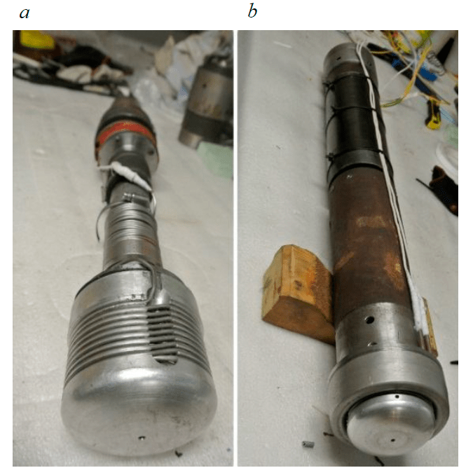
Fig.3. Model of thermohydraulic reamer-drilling tool: TRDT II (a); TRDT I (b)
The top part of the crown 16 is rigidly bolted to the frame 23. Shortened coring pipes with an outside diameter of 108 mm and a wall thickness of 4.5 mm (GOST R 51682-2000) were used as frame 23. Inside the frame 23 there is a central double pipe 24 consisting of an inner pipe 20 connected to the collector 19 and an outer pipe 24. Pipes 20 and 24 are standard steel pipes BH-48x4-A-GOST and BH-26x3-A-GOST (GOST 32678-2014). Connection of pipes in circulation system was carried out using couplings of standard industrial sizes.
A KNMS NH 26 electric heating cable is attached to the inner pipe 20. The upper part of the central double pipe 20 is attached to the pump compartment consisting of a pump frame 27 and a pump 28 installed in it. The rational choice of the pumping mechanism in the TRDT model was the electrocentrifugal pump ECN-91S, which is a part of the tools TBZS-132, TBZS-152M, TBS-112VCh and operates on direct current of voltage up to 27 V.
The TRDT II model (Fig.3, a) differs structurally from TRDT I (Fig.3, b) by absence of a crown 16 with heating elements 18 and frame 23 in the working body, all other elements remain unchanged. Technical characteristics of thermohydraulic reamer-drilling tool models are shown in Table 1.
Table 1
Technical characteristics of TRDT models
|
Parameters |
TRDT I |
TRDT II |
|
Crown diameter, mm: outer inner |
132 90 |
– – |
|
Penetrator diameter, mm |
90 |
90 |
|
Crown rated power, kW |
3.0 |
– |
|
Penetrator rated power, kW |
1.5 |
|
|
Rated power of circulation system heaters, kW |
1 |
2.5 |
|
Circulation system: outer pipe length, m outer/inner diameter inner pipe length, m outer/inner diameter |
0.4 48/40 0.4 26.8/20 |
|
|
Pump: drive motor power, kW flow rate, l/min |
ECN-91S 0.2 63.3 |
|
|
Power supply: Crown TEHs (type, voltage), V KNMS NH (type, voltage), V pump (voltage), V |
~1f, 0-220 ~1f, 0-220 27 |
|
|
Tool rated power, kW |
5.7 |
4.2 |
|
Tool length, m |
1.07 |
|
|
Tool mass, kg |
35.4 |
31.0 |
Power supply of heating elements KNMS NH 22 and 26, heating element 18 of crown 16 is carried out through AC autotransformers 8, 9 and 10, connected to the residential network. The pump 27 is connected via a laboratory AC autotransformer with rectifier 11, also connected to the residential network. Operative control is carried out by means of the control panel 13 adapted by the authors for conducted research from the small-sized drilling rig, which was developed for coring electromechani-cal drilling of glaciers on Altai. On the front of the control panel the electrical characteristics of power consumers are recorded. The drilling parameters are controlled and regulated manually. Switching on and off all energy consumers (KNMS HH 22 and 26, heating element 18 and pump 28) is carried out from control panel 13.
The test bench works as follows (Fig.4). One end of cable 7 is attached to the top of model TRDT I through block 5, the other end of cable 7 is fixed and wound on winch drum 6. The TRDT I model is lifted to maximum height, a prepared ice block 2 of cylindrical shape is placed under it and the axes of the TRDT model and ice block are centered vertically. The internal pipe space is filled with fill liquid. The TRDT model I is lowered into casing pipe 4 and its lowering is stopped when penetrator 17 reaches ice block 2. After the TRDT I model I has been placed on the ice block controlled AC current is supplied through autotransformer 8 and 9 via current conductors 12 to heating elements 22 and 18. The penetrator 17 and the crown 16 are gradually heated. On reaching a positive temperature of the working body the ice is melted and the bottomhole is formed. The drilling process continues until the volume of meltwater (heat carrier) 15 reaches the required volume for filling the circulation system, then the heating element 26 and the pump 28 are switched on. As the fig. 2 shows, the meltwater 15 through the intake windows 29 enters the central double pipe 24, the space between the outer 25 and inner 20 pipes is a suction line. The meltwater 15 rises and is forced by pump 28, from where it is pumped through the inner pipe 20 into collector 19. There it is evenly distributed in four hydraulic channels 21 of small diameter, whose tangential orientation creates at the outlet an annular circulation 30 in the near-bottomhole area.
By creating an annular circulation 30 in the near-bottomhole zone, the well walls 31 are melted in a radial direction and expansion takes place. During the circulation of meltwater 15 in the central double pipe 24, the meltwater is continuously heated, which can be quantified by thermometer readings as enthalpy. Drilling by melting with simultaneous expansion of the well in the ice mass is carried out, as a rule, to the full thickness of the ice block. The well diameter was measured using a hand-held cavernometer assembled at “Vostok” station.
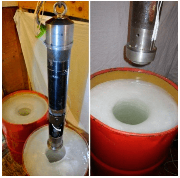
Fig.4. Appearance of the model and ice block
Results and discussion
Carrying out the planned number of experiments under the conditions of “Vostok” station has its own specifics and requires a lot of time for installation works, preparation (freezing) of ice blocks, replacement of the heating cable of KNMS NH when it fails, design changes of the working body and circulation system, adjustment and preparation of equipment. Given the complexity of the experimental investigations and the short seasonal working period, a series of experiments was carried out, including 17 successful tests. The investigations were carried out under the same conditions: ice temperature −20 (±2) °C, ambient temperature −20 (±2) °C, atmospheric pressure 450 mm Hg.
In the course of investigations (Fig.4), the main units and power supply system of the experimental test bench were tested, and the technologies for preparing artificial ice blocks with freezing the casing pipe into the ice mass and subsequent filling with low-temperature liquid were perfected. Experiments carried out on the test bench showed that freezing the casing on a depth of 150 mm in the block of artificial ice makes it possible to carry out an experiment with the penetration of 0.5-0.6 m, which corresponds to 0.5-2 h of drilling, providing complete sealing of the space inside the well. At the end of each experiment, the fill liquid and meltwater were completely pumped out of the well within 2-3 min using a hand pump.
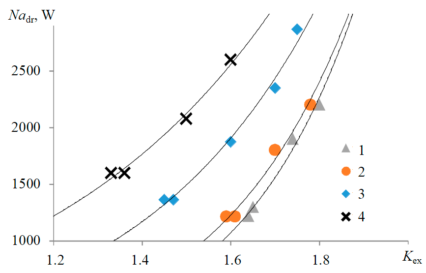
Fig.5. Experimental values for the dependence of the expansion coefficient Kex on the total active heat power Nadr Mechanical drilling-extension rate vdr 1 – 0.2; 2 – 0.3; 3 – 0.5; 4 – 0.8 m/h
When the drill model was lowered to the bottomhole under its own weight and without maintaining equilibrium by means of a winch, due to uneven distribution of thermal energy in the working body and misalignment of the model mass centre with its central axis, there was an 18° deviation from the vertical direction. In the authors' opinion, the rational choice of the method for TRDT lowering to the bottomhole is the discrete method, which ensures strictly vertical movement of the tool.
It has also been experimentally confirmed that roughness of the working body surface or minimal clogging in the bottomhole of the ice well leads to reduction of mechanical drilling rate or to a complete halt of drilling [4, 8]. To prevent such situations, it is necessary to control penetrator integrity and monitor the cleanliness of the ice surface before the start of each experiment.
The design of the TRDT I model proved unsuitable for experimental investigations, as it did not provide an expansion process. The crown heated the meltwater in the annulus and the outgoing turbulized water flow carried it upward, resulting in useless loss of thermal energy and minimizing the enthalpy in the circulation system. In addition, the tight fit of the crown to the well walls created additional hydraulic resistance as the heat carrier flowed in the near-bottomhole zone. Thus, only the TRDT II model was able to perform the experiments successfully, satisfying the requirements.
A series of experimental investigations were conducted to determine the effect of the total active heat power of the working body and circulation system, as well as (Fig.5) the mechanical drilling rate on the intensity of well expansion in the ice mass. Mechanical drilling rate varied from 0.2 to 0.8 m/h during the investigation. There were two heating elements (KNMS NH) in the design of working body of TRDT II model, the total power of which varied in the course of experiments from 1.2 to 3 kW. Specific load was reached by own weight of the model and was 17.0 kN/m2, the winch supported only vertical axial direction of the model. Pumping of the meltwater out from the bottomhole was not carried out in the process of the experiment, but only after its completion. Dimensionless expansion coefficient Kex was introduced as an expansion parameter, which is numerically equal to the ratio of expansion radius to drilling radius.
Main results of a series of experimental full diameter drilling by melting with simultaneous expansion of the borehole in the ice mass:
- Developed and manufactured model of thermohydraulic reaming drill bit according to the patent RU N 2700143 C1 for full diameter drilling by melting with simultaneous expansion of the well in ice mass is functional and suitable for experimental drilling.
- Full diameter drilling technology with simultaneous expansion of the well in ice mass can be realized with a combination of contact melting for the drilling process and the creation of a forced bottomhole annular circulation of heated heat carrier for the expansion process.
- The main factors determining the well expansion radius are the mechanical drilling rate, the active heat power of the working body and the circulation system, and the pump performance (pressure and flow rate).
- Based on results of experimental data (Fig.5) conclusions are made that during full diameter drilling by melting with simultaneous well expansion in ice mass at constant parameters of mechanical drilling rate, pump flow rate and active heat power, a truncated cone-shaped cavity with rounded corners and a large upper base is formed. With constant active heat power and increased mechanical drilling rate, the expansion radius, average meltwater temperature in the near-bottomhole zone and heat loss due to dissipation and melting of the well sidewalls are reduced. If the mechanical drilling rate is constant and the active heat power increases, the expansion radius, the average temperature of the meltwater in the near-bottomhole zone and the heat loss due to dissipation and melting of the well sidewalls increase.
- The design of TRDT model II, consisting of penetrator and double central pipe with KNMS NH heating cable wound on it with total power of 4 kW, frame and ECN-91S pump, as well as the collector made in the penetrator and horizontal hydraulic channels, which form an angle of 30° with the penetrator tangent, provide full diameter drilling with diameter of 90 mm and expansion of the ice well up to 180 mm.
- The dimensionless coefficient of well radius increase Kk at the fill liquid-meltwater interface, characterizing loss of heat energy for heating and melting of sidewalls as well as overheating of meltwater, has been determined experimentally. The coefficient varies from 0.77 to 3.33 and depends on mechanical drilling rate, expansion coefficient, total active heat power, drilling time, thermophysical properties of ice and fill liquid. As a result of experimental data processing the plane for determination of Kk is obtained, within the range of changing of expansion coefficient Kex from 1 to 2 and mechanical drilling rate of expansion vdr from 0.2 to 0.8 m/h (Fig.6). The coefficient Kk has an exponential dependence on the drilling-expansion rate and the expansion coefficient, which leads to an exponential increase in the heat energy for the drilling process with simultaneous expansion. Rational range of drilling-expansion rate is 0.5-0.8 m/h, whereby Kk does not exceed 1 (at 0.5 m penetration (Fig.6, a), which means the minimum heat loss and, correspondingly, the minimum development of expansion radius. At value vdr ≤ 0.3 m/h, Kk sharply increases, and its value exceeds 1, which leads to considerable growth of unproductive heat loss. Figure 6, b shows the Kk reduced to time.
- Rational operational parameters for the process of drilling by melting with simultaneous well expansion in ice mass using TRDT II model are achieved in the drilling-expansion rate range of 5-0.8 m/h, the ratio of drilling radius to expansion radius of 1:2 and penetration of up to 1 m. The heat input increases exponentially with increasing penetration, and the well radius at the upper limit of the expanded section is up to twice as large as the final expansion radius.
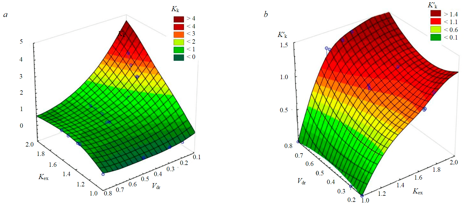
Fig.6. Empirical dependencies of well radius increase coefficient Kk on mechanical drilling-expansion rate vdr = 0.2-0.8 m/h and expansion coefficient Kex = 1-2 at drilling diameter 90 mm and penetration 0.5 m (a), drilling-expansion time of 1 h (b)
Table 2 shows the parameters that characterize the drilling by melting with simultaneous expansion as a function of the drilling rate at 0.5 m penetration and Kex = 1.6.
Table 2
Comparison of experimental data of different drilling rates
|
Parameters |
Drilling rate, m/h |
||||
|
0.2 |
0.3 |
0.5 |
0.8 |
||
|
Active heat power, kW |
1.08 |
1.24 |
1.91 |
2.56 |
|
|
Spent time, h |
2.50 |
1.67 |
1.00 |
0.63 |
|
|
Spent energy, kJ |
2.69 |
2.06 |
1.91 |
1.60 |
|
|
100%·(Qi-Qmin)/Qmin |
+67.97 |
+28.65 |
+19.06 |
0 |
|
Note. Qi – active heat power of i test, W; Qmin – minimal active heat power, spent at different drilling-expansion rates and the same 0.5 m penetration.
The meltwater temperature during the experimental investigations at drilling rates of 0.2 and 0.3 m/h was between 10-11 °C, at 0.5 m/h between 8-9 °C and at 0.8 m/h between 5-6 °C.
The results of the research show, that the lower limit of drilling rate is 0.5 m/h, when drilling rate decreases from 0.3 to 0.2 m/h, the energy consumption increases by 30.5 %, and this increase of energy consumption is attributed to useless heat loss. The upper limit of the drilling rate depends on the active heat power of the tool and the characteristics of the pump. Thus, with increase of drilling rate from 0.3 to 0.8 m/h and total active heat power from 1.24 to 2.56 kW at constant pump flow rate, the energy consumption, which ensures 60 % expansion, is 22.3 % less.
In real well conditions when drilling at great depths (2000-4000 m) the failure of heating elements is possible because of high hydrostatic pressure and poor quality of output contacts connection. The pump ECN-91S used in this design was not tested at pressure higher than 30 MPa. It is known, that wellbore 5G-1 was drilled to the depth of 2755 m with drill tool TBZS-132, which included this pump and operated successfully. Therefore, it may be supposed that ECN-91S pump is a reliable device and is quite suitable for well testing in conditions of high hydrostatic pressure.
Conclusion
The developed test bench and experimental models for simulation of drilling by melting with simultaneous expansion allowed performing the first investigations on the process of local cavities formation in ice mass by thermal method with a set geometric shape. Experimental investigations have proved the possibility for technical implementation of full diameter drilling by melting with simultaneous expansion in ice mass and allowed defining operational technological parameters of the process and ways for improvement of the equipment in use. The design of TRDT II has provided well expansion in ice mass by two times, whereas the diameter at the interface of meltwater and fill liquid or air was 4:1 in rational range of mechanical drilling-expansion rates, which is in the range of 0.5-0.8 m/h. For well expansion in ice mass more than two times with drilling diameter equal or more than 90 mm it is necessary to change ECN-91S pump by a pump with flow rate and pumping pressure.
Despite high power consumption of the process and low drilling-expansion rate (0.2-0.5 m/h), the method of drilling by melting with simultaneous well expansion in ice mass has an obvious advantage over mechanical method, which consists in destruction (melting) of ice larger in volume, which in turn increases penetration rate per trip by two times. In addition, the combination of drilling and expansion processes in one device allows reducing the number of trips and time for assembling/disassembling the drilling tool. There are no analogues of thermohydraulic reamer-drilling tool in drilling practice in terms of functionality, which is its additional advantage.
References
- Alekhina I.A., Vasiliev N.I., Lipenkov V.Y. Environment protection and environment monitoring issues in the projects of subglacial lakes studies in Antarctica. Ice and Snow. 2012. Vol. 52. N 4, p. 104-114. DOI: 10.15356/2076-6734-2012-4-104-114
- Kudryashov B.B., Solov'ev G.N. Analysis of heat exchange processes in drilling-melting of ice with a steam condenser. Journal of Mining Institute. 1981. Vol. 86, p. 111-117 (in Russian).
- Litvinenko V.S., Vasil'ev N.I. Development of a rock-destruction tool for well drilling in ice. Journal of Mining Institute. 2012. Vol. 197, p. 15-20 (in Russian).
- Onishchin V.P. A set of technical means for survey work on the Arctic seas shelf. Journal of Mining Institute. 2012. Vol. 197, p. 46-49 (in Russian).
- Vasilev N.I., Serbin D.V., Dmitriev A.N., Bolshunov A.V. Patent N 2700143 С1 RF. Thermal shell for melting drilling. Publ. 12.09.2019. Bul. N 26 (in Russian).
- Polyakova E.V. Statistical processing of the results of microstructural analysis of ice cores from deep wells at “Vostok” station (Central Antarctic). Journal of Mining Institute. 2007. Vol. 173, p. 17-19 (in Russian).
- Masolov V.N., Popov S.V., Lukin V.V., Popkov A.M. The bottom topography and subglacial Lake Vostok water body, East Antarctica. Doklady Earth Sciences. 2010. Vol. 433. N 2, p. 1092-1097 (in Russian).
- Christner B.C., Royston-Bishop G., Foreman C.M. et al. Limnological conditions in Subglacial Lake Vostok, Antarctica. Limnology and Oceanography. 2006. Vol. 51. Iss. 6, p. 2485-2501. DOI: 10.4319/lo.2006.51.6.2485
- Clow G.D., Koci B.R. A fast mechanical access drill for polar glaciology, paleoclimatology, geology, tectonics and biology. Memoirs of National Institute of Polar Research. 2002. Special issue. Vol. 56, p. 5-37.
- Barkov N.I. The first well at Vostok station. Ice and Snow. 2012. Vol. 52. N 4, p. 9-11 (in Russian).
- Yazhou Li, Talalay P.G., Xiaopeng Fan et al. Modeling of hot-point drilling in ice. Annals of Glaciology. 2021. Vol. 62. Iss. 85-86, p. 360-373. DOI: 10.1017/aog.2021.16
- Litvinenko V.S. Foreword: Sixty-year Russian history of Antarctic sub-glacial lake exploration and Arctic natural resource development. Geochemistry. 2020. Vol. 80. Iss. 3. N 125652. DOI: 10.1016/j.chemer.2020.125652
- Lipenkov V.Ya., Lukin V.V., Bulat S.A. et al. Research results of subglacial Lake Vostok during MPG period. Vklad Rossii v Mezhdunarodnyy polyarnyy god 2007/08: polyarnaya kriosfera i vody sushi. Moscow – St.Petersberg: Paulsen, 2011, p. 17-45 (in Russian).
- Vasil'ev N.I., Dmitriev A.N., Blinov P.A. Drilling a deep well at Russian “Vostok” Antarctic Station. Vestnik Otdeleniya nauk o Zemle Rossiyskoy akademii nauk. 2012. Vol. 4. N NZ2001 (in Russian). DOI: 10.2205/2012NZ000111
- Zemtsov A.A., Men'shikov N.G. A set of technical means of sampling for carbon analysis from the ice mass. Journal of Mining Institute. 1988. Vol. 116, p. 78-81 (in Russian).
- Kudryashov B.B., Men'shikov N.G. Calculation of the rate of core drilling by melting with liquid heat carrier. Journal of Mining Institute. 1993. Vol. 136, p. 6-13 (in Russian).
- Chistyakov V.K., Pashkevich V.M. Experimental test bench for investigating wellbore stability when drilling in a ice cover. Journal of Mining Institute. 1976. Vol. 71, p. 42-45.
- Litvinenko V.S. Unique technics and technologies for drilling wells in the ice of Antarctic. Journal of Mining Institute. 2014. Vol. 210, p. 5-10 (in Russian).
- Kadochnikov V.G., Dvoynikov M.V., Blinov P.A. Influence of the drill string spatial form on transport of cuttings in directional wells. Bulletin of The Association of Drilling Contractors. 2020. N 2, p. 12-19 (in Russian).
- Zelenchuk A.V., Krylenkov V. Thermohydraulic Drilling Probe for Studying Ice Sheets and the Subglacial Environment of the Earth and Others Heavenly Bodies. Emerging Challenges in Environment and Earth Science. 2022. Vol. 3, p. 41-50. DOI: 10.9734/bpi/ecees/v3/15837D
- Polyakova E.V. Structural features of Lake Vostok ice (Central Antarctic). Journal of Mining Institute. 2009. Vol. 182,p. 45-47 (in Russian).
- Bulat S.A., Alekhina I.A., Lipenkov V.Y. et al. Cell Concentrations of Microorganisms in Glacial and Lake Ice of the Vostok Ice Core, East Antarctica. Microbiology. 2009. Vol. 78. Iss. 6, p. 808-810. DOI: 10.1134/S0026261709060216
- Fricker H.A., Powell R., Priscu J. et al. Siple Coast subglacial aquatic environments: the Whillans Ice Stream Subglacial Access Research Drilling (WISSARD) Project. Proceedings of the Chapman Conference on the Exploration and Study of Antarctic Subglacial Aquatic Environments. Washington: American Geophysical Union, 2011, p. 199-220. DOI: 10.1029/2010GM000932
- Kennicutt M.C., Siegert M.J. Subglacial Aquatic Environments: A Focus of 21st Century Antarctic Science. Washington: American Geophysical Union, 2011, p. 1-8. DOI: 10.1002/9781118670354.CH1
- Lukin V.V., Vasiliev N.I. Technological aspects of the final phase of drilling borehole 5G and unsealing Vostok Subglacial Lake, East Antarctica. Annals of Glaciology. 2014. Vol. 55. Iss. 65, p. 83-89. DOI: 10.3189/2014AoG65A002
- McKay R.M., Barrett P.J., Levy R.S. et al. Antarctic Cenozoic climate history from sedimentary records: ANDRILL and beyond. Philosophical Transactions of the Royal Society. A: Mathematical, Physical and Engineering Sciences. 2016. Vol. 374. Iss. 2059. DOI: 10.1098/rsta.2014.0301
- Makinson K., Anker P., Garcés J. et al. Development of a clean hot water drill to access Subglacial Lake CECs, WestAntarctica. Annals of Glaciology. 2021. Vol. 62 (85-86), p. 250-262. DOI: 10.1017/aog.2020.88
- Priscu J.C., Powell R.D., Tulaczyk S. Probing subglacial environments under the Whillans Ice Stream. Eos. 2010. Vol. 91. N 29, p. 253-254. DOI: 10.1029/2010EO290002
- Siegert M.J., Ross N., Le Brocq A.M. Recent advances in understanding Antarctic subglacial lakes and hydrology. Philosophical Transactions of the Royal Society. A: Mathematical, Physical and Engineering Sciences. 2016. Vol. 374. Iss. 2059. DOI: 10.1098/rsta.2014.0306
- Kupavykh K.S., Kupavykh A.S., Morenov V.A. Analysis of Implementation Effectiveness of Two Working Fluids Characterized by Different Viscoelastic Characteristics at Hydrodynamic Impact on the Borehole Bottom Zone. Science & Technique. 2019. Vol. 18. N 2, p. 164-170. DOI: 10.21122/2227-1031-2019-18-2-164-170
- Weiss P., Yung K.L., Ng T.C. et al. Study of a thermal drill head for the exploration of subsurface planetary ice layers. Planetary and Space Science. 2008. Vol. 56. Iss. 9, p. 1280-1292. DOI: 10.1016/j.pss.2008.04.004
- Serbin D.V., Vasil'ev N.I., Dmitriev A.N., Bolshunov A.V. Thermal tool for drilling by melting with simultaneous expansion of ice wells. Materialy XIV Mezhdunarodnoy nauchno-prakticheskoy konferentsii “Novye idei v naukakh o Zemle”. Moscow: Rossiyskiy gosudarstvennyy geologorazvedochnyy universitet imeni Sergo Ordzhonikidze, 2019. Vol. 4, p. 297-300.
- Hoseon Yoo. Analytical solutions to the unsteady close-contact melting on a flat plate. International Journal of Heat and Mass Transfer. 2000. Vol. 43. Iss. 8, p. 1457-1467. DOI: 10.1016/S0017-9310(99)00221-5
- Zelenchuk A.V., Krylenkov V.A. Probes for the study of icy and subglacial environment of planets. Ice and Snow. 2019. Vol. 59. N 1, p. 123-134 (In Russian). DOI: 10.15356/2076-6734-2019-1-123-134
- Wirtz M., Hildebrandt M. IceShuttle Teredo: An Ice-Penetrating Robotic System to Transport an Exploration AUV into the Ocean of Jupiter's Moon Europa. 67th International Astronautical Congress (IAC), 26-30 September 2016, Guadalajara, Mexico. N 34241.