Development of the technology of stowing the developed space during mining
- 1 — Ph.D. Associate Professor Saint Petersburg Mining University ▪ Orcid
- 2 — Postgraduate Student Saint Petersburg Mining University ▪ Orcid

Abstract
An analysis of the world experience in the development of potash deposits shows that the main problems arising during their development are a high level of mineral losses, an increased risk of flooding of mine workings as a result of water-proof layer discontinuance and the development of emergency water inflows in the mined-out spaces. Reduction of potash ore losses can be achieved by using a long-pillar mining system, but this method is limited by the peculiarities of the geological structure of the potash deposits and the need to preserve the continuity of the water-proof layer during its underworking. The safety of underworking of the water-proof layer can be improved by using the stowing of the developed longwall space. However, the question of the influence of the stowing on the height of the zone of water supply cracks development remains little-studied. The world experience of stowing the developed spaces in the development of layers with long pillars is analyzed and the technology of placing the stowing masses, which can solve these problems, is proposed. The considered technology and the proposed solutions are supported by laboratory tests of stowing materials and mathematical modeling of deformation zones in the overlying rocks.
None
Introduction
The rate of potash ore mining is constantly increasing, and this trend will continue [1, 2]. Potash fertilizers are produced in Canada, Belarus, Russia, Germany, China and other countries [3]. 31 % of the world's potash reserves are concentrated in Russia. The extraction of salts in Russia by the traditional mining method is carried out at three deposits: Verkhnekamskoye, Iletskoye and Tyretskoye. At two deposits – Gremyachinskoye and Nivenskoye – work is underway to develop reserves, which are also planned for underground mining [4].
The specifics of the potash deposits development are associated with the high solubility of salts and the presence of water-bearing layers in the covering rocks, so the urgent task is to prevent the processes leading to flooding of the mine [5]. Subsurface users are forced to reduce the extraction coefficient to reasonable limits (in some cases up to 30 %) and apply a soft technology of short-face mining with the ore pillars leaving to preserve safe conditions for working in the water-proof layer [6].
The analysis of statistics of catastrophic water and brine breakthroughs in potash mine workings shows that over the past 100 years, such cases have been recorded on average once every 3-5 years in the world, in Russia and neighboring countries – once every 10-20 years (Table 1). In world practice, about 80 salt mines were flooded and could not be restored [7], including three mines at the Verkhnekamskoye potash-magnesium salt deposit [8-10]. The main reason for flooding of the mines is the formation of man–made water supply channels in the covering water-proof layer as a result of its underworking, which is why up to 50 % of potash companies in the world shut down before the end of the development of the reserves [11]. The breakthrough of brines into the potash mine workings leads to its uncontrolled flooding, an environmental disaster in the development region, loss of reserves and huge economic damage [12]. It is possible to reduce the probability of the formation of water supply channels in the water-proof layer and further flooding of the mine by controlling the roof by stowing the developed space in the mining process [13].
Table 1
Chronology of accidents at potash mines in Russia
|
The year of the accident |
Mine |
Type of deposit |
Accident |
|
1979 |
Sol-Iletsky mine N 1 |
Dome |
Flooding |
|
1986 |
BKRU-3 |
Formation |
Flooding |
|
1995 |
SKRU-2 |
Formation |
Failure |
|
2006 |
BKRU-1 |
Formation |
Flooding |
|
2014 |
SKRU-2 |
Formation |
Breakthrough of above-salt waters |
Thus, when developing salt deposits, it is necessary to solve two interrelated problems – a high level of losses and an increased risk of flooding of mine workings. The problems can be solved with the help of a long-pillar development system with stowing of the developed space. However, to do this, it is necessary to ensure the safety of the water-proof layer by stowing the developed space.
When stowing out the developed space, an artificially created stowing mass acts as a bearing element and, therefore, affects the nature of changes in the parameters of the stress-strain state (SSS) of the enclosing rock mass, including that in the underworked zones. However, as the practice of mining operations at potash-magnesium deposits shows, the influence of the stowing masses of the developed longwall space on the state of the water-proof layer (WPL) is not taken into account in the existing regulatory and technical documentation [14]. Also, the issues of effective technology for the construction of stowing masses behind long stoping faces in potash deposits and the justification of their necessary physical and mechanical properties have not been sufficiently studied.
The experience of mining potash mines shows that savings on stowing works are incomparable with financial losses when the mine is flooded [15, 16]. According to estimates, as a result of flooding of the mine with approved reserves for 20 years of mining, the lost profit will amount to about 60 billion rubles. According to the matrix for assessing the consequences of man-made risks [17], the probability of mine flooding, characterized by a frequency of 1 to 0.1 times a year and financial damage to the company of more than $ 100 million, should be attributed to a very high risk that requires immediate implementation of measures to reduce it and increased attention from the subsoil user. Due to the high risks of flooding, the need for stowing the developed spaces is justified.
Experience in the application of selective excavation technologies at the mines of Belaruskali OJSC
An analysis of the current experience in the development of potash deposits shows that long-pillar mining systems with the stowing of the worked-out space during the development of salt layers have found application only at the Starobinskoye deposit [18]. At this potash salt deposit, mining-geological and hydrogeological conditions are relatively favorable, therefore, the stowing is used not to reduce the development of water supply cracks over the worked-out space, but to place waste rock from the interlayers in the worked-out space and improve the quality of ore delivered to the factory.
The stowing is carried out by stowing out rubble bands behind the mechanized complex with the help of throwers located in pre-mined stowing drifts. The disadvantages of this scheme are the significant shrinkage of the rubble bands after contact with the roof rocks and their low bearing capacity, due to the fact that the stowing material spreads apart under pressure due to the absence of side stops. Also, this technology does not solve the problem of disposal of liquid waste produced as a result of the enrichment of potash ore.
Experience in the application of technologies of full mechanized stowing of longwalls in the coal mines of China
During the development of flat-lying coal seams, the stowing of worked-out spaces of longwalls has found application in the coal mines of China. The stowing is carried out with the help of special laying equipment integrated into the mechanized complex [19, 20]. The support in the back is equipped with a blockage and a compaction mechanism. A stowing scraper conveyor is suspended to the blockage shield, which receives the stowing material and is poured onto the ground of the worked-out space through holes opened in the conveyor belt. After the formation of the fill, the rock is compacted with a compaction mechanism.
The disadvantages are the complexity of delivering the stowing material from the surface to the worked-out space, the need for periodic stops of the stoping face due to the duration of the stowing work, as well as the low manufacturability of the complete stowing of the worked-out space. This technology also does not solve the problem of disposal of liquid waste generated as a result of the enrichment of potash ore.
The developed technology of placement of stowing masses in the developed longwall space
As an alternative to traditional pillar systems of development for the conditions of promising potash-magnesium deposits, a technology for placing stowing masses in the developed spaces of longwalls equipped with mechanized complexes can be proposed [21]. It is proposed to place a stowing in the form of a hardening hydro-stowing mixture in the developed space inside elastic reservoirs made of waterproofing material, which are located in the developed space in the form of bands perpendicular to the longwall face (Fig.1). The hardening hydro-stowing mixture is delivered to the reservoirs through stowing pipelines, which are mounted in pre-mined conveyor ventilation and stowing drifts. As the longwall moves, sections of the stowing pipelines are dismantled. The reservoirs are attached to the support sections from the side of the developed space or deli-vered piece by piece to the location. Reservoirs should ensure the preservation of a given shape when they are filled to the height of the developed space. During the time that the reservoir closest to the face is filled, the previous one, filled, gains strength.
The composition of the stowing mass is selected in such a way to exclude the formation of water supply channels in the water-proof layer. The time to reach the required load-bearing capacity of the stowing mass is set in accordance with the required speed of moving the face. By the time the stowing mass comes into contact with the roof rocks, the stowing mass has the necessary strength properties (Fig.2).
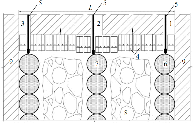
Fig.1. Schematic diagram of the technology of placement of stowing masses in the developed longwall space [21] 1 – longwall conveyor drift; 2 – longwall stowing drift; 3 – longwall ventilation drift; 4 – support sections; 5 – stowing pipeline; 6 – reservoir; 7 – stowing material; 8 – developed space; 9 – barrier pillar

Fig.2. Scheme of the stowing masses location in the developed longwall space 1 – stowing pipeline; 2 – stowing material; 3 – reservoir; 4 – support sections; 5 – ground; 6 – roof; 7 – formation
The parameters of the stowing mass bands – width, distance between them and their number – should be linked to the parameters of the roof movement. The height of cracking after deformations of the overlying rocks should be less than the geological capacity of the WPL with the retention of a protective water-proof ceiling [14].
Methodology
The experience of mining potash deposits shows that the most technologically advanced types of stowing in conditions of salt mines are [22]:
- a loose stowing from the destroyed waste rock obtained as a result of tunneling or selective excavation and placed in the worked-out space by a mechanized method (actively used in the mines of the Starobinsky deposit) [16];
- hydraulic “self-hardening” stowing based on salt waste, fed into the worked-out space in the form of pulp, giving brine and crystallizing (actively used in the mines of the Verkhnekamskoye deposit, including the formation of softening zones) [23].
In the laboratory of Physical and Mechanical properties and Destruction of Rocks of the Center of Geomechanics and Mining Issues of the St. Petersburg Mining University, the physical and mechanical and deformation properties of the stowing masses were investigated. The experiment was carried out in two stages to study each type of stowing (loose and hydraulic) in the conditions of the Nivenskoye deposit [24].
At the first stage of the experiment for loose stowing, the dependence of the shrinkage of destroyed salt rocks on the applied load was investigated. The halite rock used in the laboratory experiment was selected from core material at the Nivenskoye potash-magnesium salt deposit from a depth of 1000-1100 m. The selected material was prepared for uniaxial compression tests by preliminary crushing and sieving through a group of sieves (mm): 5.00-7.00; 3.00-5.00; 2.00-3.00; 1.00-2.00; 0.25-1.00; <0.25. Such a range of fractional separation fully enough corresponds to the real granulometric composition of salt rocks during their mechanical destruction. Granulometric composition of the waste rock from the excavation, depending on the fraction of size (mm) and the total content of the class (%): 100.0-50.0/15.0; 50.0-25.0/17.0; 25.0-10.0/14.0; 10.0-5.0/12.0; 5.0-3.0/11.0;3.0-2.0/9.0; 2.0-1.0/7.0; 1.0-0.5/5.0; 0.5-0.2/8.0; 0.2-0.1/2.0.
The samples were tested by fractions in the mode of specified deformations in a steel cylindrical vessel with a size of 150×150 mm, i.e. in a clamped medium. Testing of loose samples under such conditions made it possible to reflect the behavior of the material under study in an elastic core of volumetric compression formed inside a real stowing mass as the load from the descending roof rocks is transferred to it [14].
The results showed that the fraction size above 2 mm practically does not affect the reduction of shrinkage, i.e. with a higher concentration of fine fraction in the composition of the stowing, it is possible to improve compression properties.
After processing the experimental data, the resulting shrinkage curve of the loose halite stowing material was constructed depending on the applied load (Fig.3, a).
According to the schedule, at the depth of the productive layers of the Nivenskoye deposit (about 1100 m), after stabilization of the displacement processes, we should expect shrinkage of the stowing mass left in the developed longwall space to values of about 35% of the original height.
The obtained experimental generalized shrinkage curve of loose stowing material is described by the equation:
where ε0 – deformation parameter depending on the size of the loose material fraction (in the first approximation for the generalized curve ε0 = 35 %), %; σ – compressive pressure acting on the material, MPa; n – an empirical parameter depending on the size of the bulk material fraction (in the first approximation for the generalized curve n = 7.3 MPa), MPa.
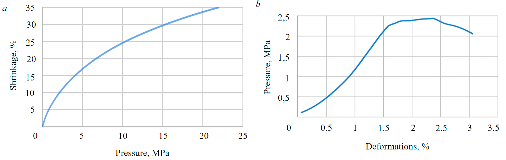
Fig.3. Generalized graph of the dependence of the shrinkage of a loose stowing from crushed halite (a) and a hydraulic stowing based on salt waste (b) on the applied pressure
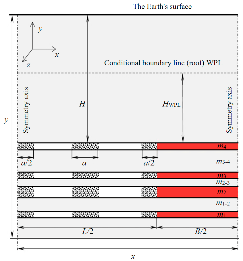
Fig.4. Draw of the design scheme (model) for placing the stowing material in the worked-out space of longwall in the form of bands from reservoirs
In the second stage of the experiment, the strength properties of samples formed as a result of natural crystallization were studied for hydraulic stowing based on salt waste. Crushed halite rock was prepared for the production of the hydraulic-stowing pulp, which was gaged with saturated brine. The crystallization and solidification process of the samples lasted up to three months.
During the experiment, it was possible to achieve solidification of samples in laboratory conditions and the formation of crystalline bonds between salt particles, which allowed the formed samples to gain strength characteristics. The finished samples of the stowing masses were tested for strength and brought to the limit state. After processing the experimental data, the resulting deformation curve of the stowing mass was constructed based on the hydraulic stowing depending on the applied load (Fig.3, b). The strength properties of hydraulic masses can be increased to the required limit by adding binding additives to the composition of the stowing [25, 26].
The obtained curve shapes correspond to the results of studies carried out by specialists at the Starobinskoye and Verkhnekamskoye deposits [14, 27], as well as with foreign experience in studying the compression properties of the stowing [28].
To assess the stress-strain state of the water-proof layer, computer modeling was carried out [24, 29, 30]. Based on the data obtained in the FLAC2D software package, a mining and geomechanical model of the technology for placing stowing masses in the form of reservoirs in the worked-out space of longwalls during the development of four potash seams was developed using the example of idealized conditions of the Nivenskoye deposit of potash-magnesium salts (Fig.4). For the same conditions, the stress-strain state of the roof was modeled when working out layers without the use of a stowing and when stowing with rubble bands according to the experience of Belaruskali OJSC with subsequent comparison of the results.
Initial data for modeling: the number of layers being developed – 4; the numbering of the layers is from bottom to top; the order of mining is descending; the occurrence of the layers is horizontal; the longwalls and the inter-pillars are located on different layers coaxially; the extracted thickness of the first layer m1 – 2 m; the second layer m2 – 4 m; the third layer m3 – 2 m; the fourth layer m4 – 2 m; the total extracted thickness m – 10 m; the thickness between the first and second layers m2-1 – 4 m; the thickness between the second and third layers m3-2 – 2 m; the thickness between the third and fourth layers m4–3 – 10 m; the depth of the roof of the upper worked layer m4 – H = 1100 m; geological thickness WPL – H = 350 m; Young's modulus of the host rocks and layers – 10000 MPa; Poisson's ratio – 0,3; tensile strength – 1,0 MPa; bonding strenght – 5 MPa; angle of internal friction – 30°; length of the longwalls on the layers being worked out – L = 300 m; width of the inter-pillars – B = 60 m; а – width of the stowing mass (assumed to be 20 m in the simulation).
Discussion
The models show the zones of development of vertical tensile deformations over the developed longwall space, which corresponds to the formation of horizontal stratifications (Fig.5). These areas, together with zones of horizontal tension in the marginal parts of the worked-out spaces, can be interpreted as possible areas for the formation of water supply cracks. In the case of mining without a stowing, the capacity of the water supply crack zone (WSCZ) is about 226 m in height above the upper layer being worked out (Fig.5, a). Without carrying out measures to stowing the developed space, the final subsidence (after working out all four layers in the formation) at the WPL level is about 60 % of the extracted capacity, which can lead to the formation of dangerous conditions for side work in the marginal parts at the long-stopped boundaries of mining operations.
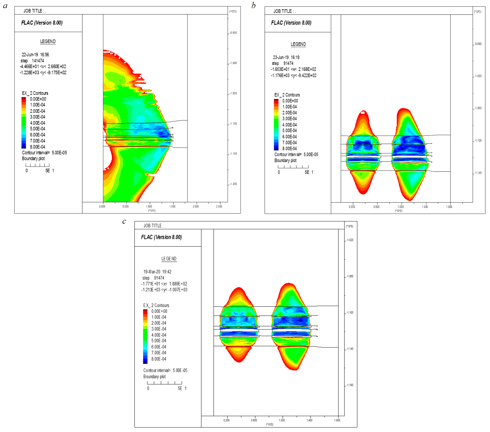
Fig.5. Fall arches (zone of development of tensile vertical deformations): а – after working out all the layers in the formation without stowing; b – after working out all the layers in the formation with mechanized stowing of the worked–out space in the form of bands of loose material; c – after working out all the layers in the formation with stowing of the worked-out space in the form of bands from reservoirs with the stowing material in the form of a hardening hydro-stowing mixture
When working out with mechanized stowing of the worked-out space in the form of bands of loose material, the power of the WSCZ is about 188 m in height above the upper layer being worked out (Fig.5, b). Placing the stowing material in the form of bands reduces the amount of subsidence during loose stowing to ~26.5 % of the output thickness.
When working out with the stowing of the worked-out space in the form of bands from reservoirs with the stowing material in the form of a hardening hydro-stowing mixture, the WSCZ capacity is about 170 m in height above the upper layer being worked out (Fig.5, c). Placing the stowing material in the form of bands from the reservoirs reduces the amount of subsidence during hydraulic stowing to ~ 21 % of the removed capacity. The results of the modeling are shown in Table 2.
Table 2
Height WSCZ above the roof of the formation series
|
The stage of working out(descending order) |
Total extracted thickness, m |
Without stowing works, m |
Bands of loose material, m |
Bands of hardeninghydro-stowing mixture, m |
|
The first layer |
2,0 |
186 |
117 |
102 |
|
The second layer |
4,0 |
193 |
154 |
134 |
|
The third layer |
8,0 |
226 |
175 |
163 |
|
The fourth layer |
10,0 |
226 |
188 |
170 |
Conclusion
Statistics on the development of potash-magnesium deposits by the mine method indicates that potash-magnesium mines operate in conditions of very high risk due to the factor of the development of catastrophic processes in the water-proof layer, leading to flooding of workings and loss of reserves. Due to the high risks of the water supply channels formation in WPL during the development of potash-magnesium deposits, subsurface users are forced to use soft technologies of extraction by pillar systems with the pillars leaving and with a low extraction coefficient.
It is proposed to place self-hardening hydraulic masses behind longwalls based on salt waste in the form of bands perpendicular to the longwall face. To prevent the pulp from spreading, it is fed into elastic reservoirs placed behind a mechanized support. This technology allows to collectively solve the problems of excess liquid waste of enrichment and reducing the height of water supply cracks, as well as, due to the possible use of long-pillar systems under water-bearing levels, increase the extraction coefficient.
As the modeling results show, the decrease in the height of the water supply channels zone above the worked-out space of the simulated longwall when placing bands of self-hardening stowing material based on salt waste behind the face reaches 16 % of the height of the water supply channels zone without the use of stowing and up to 10 % of the height of the water supply channels zone with the use of loose stowing.
References
- Dergachev A.L., Starostin V.I. Trends in Mineral Complex Development at the Turn of the Centuary. Moscow University Bulletin. Series 4. Geology. 2018. N 1, p. 3-15 (in Russian). DOI: 10.33623/0579-9406-2018-1-3-15
- Ciceri D., Manning D.A.C., Allanore A. Historical and technical developments of potassium resources. Science of the Total Environment. 2015. Vol. 502, p. 590-601. DOI: 10.1016/j.scitotenv.2014.09.013
- Vysotskii E.A., Gubin V.N., Kutyrlo V.E. Economic and geographical aspects of the potash industry of the world. Vestnik Bryanskogo gosudarstvennogo universiteta. Seriya 2. 2007. N 1, p. 90-96 (in Russian).
- Baturin E.N., Menshikova E.A., Blinov S.M. et al. Problems of development of the largest potash deposits in the world. Sovremennye problemy nauki i obrazovaniya. 2012. N 6. URL: https://www.science-education.ru/ru/article/view?id=7513 (accessed 16.06.2021).
- Kulikova A.A., Ovchinnikova T.I. On the issue of reducing geoecological risks at mining enterprises. Mining informational and analytical bulletin. 2021. N 2-1, p. 251-262 (in Russian). DOI: 10.25018/0236-14932021-21-0-251-262
- Zubov V.P. Applied technologies and current problems of resource-saving in underground mining of stratified deposits. Gornyi zhurnal. 2018. N 6, p. 77-83 (in Russian). DOI: 10.17580/gzh.2018.06.16
- Poborska-Młynarska K. Katastrofy wodne w górnictwie solnym na świecie – przyczyny, sposoby zwalczania, skutki. PRZEGLĄD GÓRNICZY. 2018. Vol. 74. N 6, p. 33-41 (in Polish).
- Laptev B.V. Emergency situations at the Verkhnekamsk deposit of potash and magnesium salts. Bezopasnost truda v promyshlennosti. 2009. N 8, p. 28-31 (in Russian).
- Laptev B.V. Historiography of accidents during the salt deposits development. Bezopasnost truda v promyshlennosti. 2011. N 12, p. 41-46 (in Russian).
- Sankovskii A.A., Alekseenko A.G. Analysis of Practical Experience of Processing of the Sweet of Approximate Plasts in the Conditions of Mercenaries of the Verkhnekamsk Deposit of Potassium Magnesium Salts at the Use of Short Cleaning System Development Systems. Mine Surveying Bulletin. 2018. N 4 (125), p. 41-51 (in Russian).
- Shuvalov Yu.V., Kovalev O.V., Mozer S.P. et al. On the issue of reducing investment risks in the potash deposits development. Mining informational and analytical bulletin. 2010. N 11, p. 366-372 (in Russian).
- Semenova T., Al-Dirawi A. Economic Development of the Iraqi Gas Sector in Conjunction with the Oil Industry. Energies. 2022. Vol. 15. Iss. 7. N 2306. DOI: 10.3390/en15072306
- Fliß T., Marx H., Thona H. Backfilling and Pillar Re-Mining in Potash Industry. MINEFILL 2011 – International Conference on Mining with Backfill, 21-25 March 2011, Cape Town, South Africa. K-UTEC AG Salt Technologies Sondershausen, 2011, p. 1-14.
- Deshkovskii V.N., Novokshonov V.N., Palto P.P. Development of a methodology for calculating the height of the distribution of the water supply cracks zone for pillar development systems with partial stowing of the developed space in the form of rubble bands. Gornaya mekhanika. 2007. N 2, p. 77-84 (in Russian).
- Zubov V.P., Smychnik A.D. The concept of reducing the risks of potash mines flooding caused by groundwater inrush into excavations. Journal of Mining Institute. 2015. Vol. 215, p. 29-37 (in Russian).
- Kowalewski O., Spiewanowski P. Stock market response to potash mine disasters. Journal of Commodity Markets. 2020. Vol. 20. N 100124. DOI: 10.1016/j.jcomm.2020.100124
- Porter M., Lato M., Quinn P., Whittall J. Challenges with use of risk matrices for geohazard risk management for resource development projects // Mining Geomechanical Risk, 9-12 April 2019, Perth, Australia. Australian Centre for Geomechanics, 2019, p. 71-84. DOI: 10.36487/ACG_rep/1905_01_Porter
- Solovev V.A., Aptukov V.N., Chernopazov D.S. et al. Aspects of improving the efficiency of the Verkhnekamsk potash deposit development. Novosibirsk: Nauka, 2019, p. 179 (in Russian).
- Jixiong Zhang, Zhang Qiang, Qiang Sun et al. Surface subsidence control theory and application to backfill coal mining technology. Environmental Earth Sciences. 2015. Vol. 74, p. 1439-1448. DOI: 10.1007/s12665-015-4133-0
- Xiaowei Feng, Nong Zhang, Lianyuan Gong. Application of a Backfilling Method in Coal Mining to Realise an Ecologically Sensitive “Black Gold” Industry. Energies. 2015. Vol. 8. Iss. 5, p. 3628-3639. DOI: 10.3390/en8053628
- Gromtsev K.V., Kovalskii E.R. Patent N 2735173 RF. The method of stowing the developed space in the development of flat-lying seams with long pillars. Publ. 28.10.2020. Bul. N 31 (in Russian).
- Khayrutdinov A.M., Kongar-Syuryun Ch., Kowalik T., Faradzhov V. Improvement of the backfilling characteristics by activation of halite waste for non-waste geotechnology. 12th International Scientific Conference of Civil and Environmental Engineering for PhD. Students and Young Scientists, 15-16 October 2020, High Tatras, Slovaki. IOP Conference Series: Materials Science and Engineering, 2020. Vol. 867. N 012018. DOI: 10.1088/1757-899X/867/1/012018
- Baryakh A.A., Gubanova E.A. On flood protection measures for potash mines. Journal of Mining Institute. 2019. Vol. 240, p. 613-620. DOI: 10.31897/PMI.2019.6.613
- Kovalskii E.R., Gromtsev K.V., Petrov D.N. Modeling Deformation of Rib Pillars during Backfill. Mining informational and analytical bulletin. 2020. N 9, p. 87-101 (in Russian). DOI: 10.25018/0236-1493-2020-9-0-87-101
- Votyakov M.V. Increasing the completeness of the extraction of potash ore reserves based on the laying of the developed space with halite waste: Avtoref. dis. … kand. tekhn. nauk. Moscow: Moskovskii gosudarstvennyi gornyi universitet, 2009, p. 24 (in Russian).
- Shkuratskii D.N., Rusakov M.I. Using Industrial Wastes of Potash Manure Production at Rock Mixtures for Backfilling Gobs. News of the Tula state university. Sciences of Earth. 2015. N 3, p. 87-97 (in Russian).
- Shvab R.G., Deshkovskii V.N. Management of the under-mined rock mass condition by partial stowing of the worked-out space in the form of rubble bands from crushed halite during the potash ore reserves extraction by a pillar mining system. Problemy ratsionalnogo prirodopolzovaniya: materialy mezhdunarodnoi nauchno-prakticheskoi konferentsii, 29-31 oktyabrya 2008, Perm, Rossiya. Izd-vo PGTU, 2008, p. 56-63 (in Russian).
- Lüdeling C., Minkley W. A Crushed-Salt Model with Creep, Compaction and Strain Softening, and Application to Tailings Heaps. 48th U.S. Rock Mechanics/Geomechanics Symposium, 1-4 June 2014, Minneapolis, Minnesota, USA. One Petro, 2014. N ARMA-2014-7037. DOI: 10.1002/nag.220
- Kovalev O.V., Mozer S.P., Tkhorikov I.Yu., Sankovskii A.A. Rock mechanics problems decision algorithm for bottom layers of potash salt deposits. Journal of Mining Institute. 2014. Vol. 207, p. 60-62 (in Russian).
- Kovalskii E.R. Purposes of numerical experiment in rock mechanics. Journal of Mining Institute. 2013. Vol. 205, p. 57-59 (in Russian).