
Effect of shear stress on the wall of technological pipelines at a gas condensate field on the intensity of carbon dioxide corrosion
- 1 — Ph.D., Dr.Sci. professor Ufa State Petroleum Technological University ▪ Orcid ▪ Elibrary ▪ Scopus ▪ ResearcherID
- 2 — Postgraduate Student Ufa State Petroleum Technological University ▪ Orcid ▪ Elibrary ▪ Scopus ▪ ResearcherID

Abstract
The object of the study is a section of the gas and gas condensate collection system, consisting of an angle throttle installed on a xmas tree and a well piping located after the angle throttle. The aim of the study is to assess the impact of the flow velocity and wall shear stress (WSS) on the carbon dioxide corrosion rate in the area of interest and to come up with substantiated recommendations for the rational operation of the angle throttle in order to reduce the corrosion intensity. In the course of solving this problem, a technique was developed and subsequently applied to assess the influence of various factors on the rate of carbon dioxide corrosion. The technique is based on a sequence of different modeling methods: modeling the phase states of the extracted product, three-dimensional (solid) modeling of the investigated section, hydrodynamic flow modeling of the extracted product using the finite volume method, etc. The developed technique has broad possibilities for visualization of the obtained results, which allow identifying the sections most susceptible to the effects of carbon dioxide corrosion. The article shows that the average flow velocity and its local values are not the factors by which it is possible to predict the occurrence of carbon dioxide corrosion in the pipeline section after the angle throttle. The paper proves that WSS has prevailing effect on the corrosion intensity in the section after the angle choke. The zones of corrosion localization predicted according to the technique are compared with the real picture of corrosion propagation on the inner surface of the pipe, as a result of which recommendations for the rational operation of the angle throttle are formed.
None
Introduction. Corrosion of pipelines and equipment is a common occurrence in hydrocarbon production. The most well-studied is the corrosion of oilfield equipment. Recently, the less studied issue of corrosion of equipment and pipelines at gas and gas condensate fields has become increasingly important [3, 4]. This is primarily due to the beginning of the development of deep-located deposits, the fluid of which contains carbon dioxide [5, 12].
The corrosion rate Vcor in the presence of carbon dioxide can be influenced by various factors. Many experts studied this issue [16], and today the following understanding of the problem has been unambiguously formed.
With an increase in temperature, Vcor increases because carbon dioxide corrosion is an electrochemical process, and it is subject to the Arrhenius equation, according to which the reaction intensity rises with increasing temperature [8]. However, under certain conditions, upon reaching a temperature of 60-70 °C a dense layer of corrosion products can form on the metal surface, which has high adhesion properties and low penetrability. This layer acts as a protective film [13]. Thus, when a certain temperature value is exceeded Vcor.
Pressure does not directly affect the corrosion rate; however, with an increase in the working pressure, the solubility and partial pressure of carbon dioxide grow, and, accordingly, the level of CO2 concentration in the liquid rises, pH decreases, and Vcor increases.
The flow velocity also influences the corrosion rate. With its increase, Vcor rises smoothly due to the facilitation of the mass transfer process for both depolarizers and the resulting corrosion products [2, 9]. When the critical value of the flow velocity is reached, the corrosion inten sity sharply increases due to the addition of the erosion factor [7, 17]. However, the flow velocity indicator, as a rule, is the average value over the entire pipe cross-section, or is tied to the velocity of one of the phases in the case of a multiphase flow. In addition, the extracted product can be transported under various temperature and pressure conditions and have various viscosity and density.
A more indicative parameter, which takes into account all the above factors for assessing the degree of corrosion, is the wall shear stress (WSS)[6]. In the literature, to describe this parameter, such terms as shear stress and dynamic velocity, depending on the WSS and the density of the medium, are used [1]. In contrast to the flow velocity, the WSS value gives a more accurate idea of the corrosion conditions: the higher the WSS value, the more intense the corrosion process. This is because WSS describes the properties of the boundary layer in the medium flow formed near the inner surface of the pipe. Therefore, at high values of WSS, the boundary layer of the medium (regardless of the aggregative state) is capable of mechanically tearing off the film of corrosion products from the metal surface. The presence of corrosion products, in turn, contributes to a decrease in the corrosion rate, inhibiting the reduction processes in the cathode sections and the transition of metal ions into solution in the anode sections. Thus, continuous tearing off the film constantly provokes high-intensity corrosion processes.
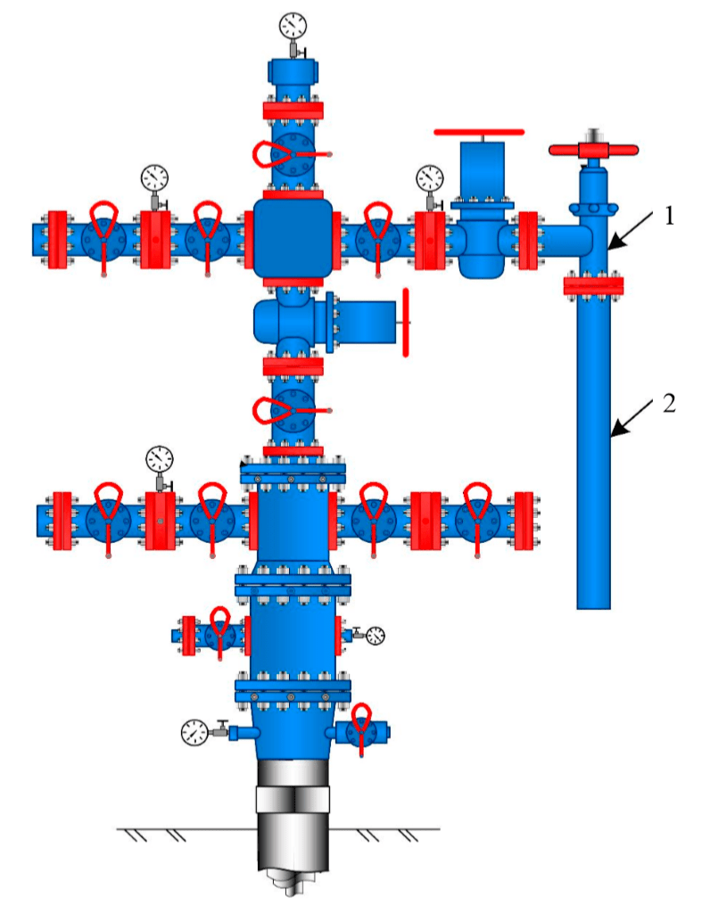
There are many mathematical models describing the process of carbon dioxide corrosion [1], some of which take into account the mentioned above factors. Some models are empirical, based on laboratory and field data, and statistically processed [18]. Others are based on mechanistic modeling [15]. In this case, physical and chemical laws are taken as a basis, in accordance with which various stages of carbon dioxide corrosion take place. The third, integrated type of models, combines the two previous ones [14]. In this case, the authors calibrate the mechanistic models using the results of corrosion tests. Despite extensive modeling experience, there are a number of situations in which known models are unable to predict the actual rate of corrosion. In particular, during production of gas and gas condensate, an angular pressure regulator (angle throttle) is installed on a xmas tree in some cases (Fig.1). If the extracted product contains carbon dioxide, carbon dioxide corrosion is possible in the pipeline section after the pressure regulator. Existing models of carbon dioxide corrosion are not able to identify specific areas where maximum corrosion will occur. They can only predict the average Vcor for the entire section, despite the fact that due to the peculiarities of hydrodynamics and different values of WSS, caused by additional erosion effects on the inner surface of the pipe, local areas of intense carbon dioxide corrosion can form.
The main objective of the article is to prove the prevailing influence of the WSS on the rate of carbon dioxide corrosion in the pipeline section after the angle throttle and to issue substantiated recommendations for the rational operation of the angle throttle in order to reduce the corrosion intensity when using the method of modeling the flow of the extracted product.
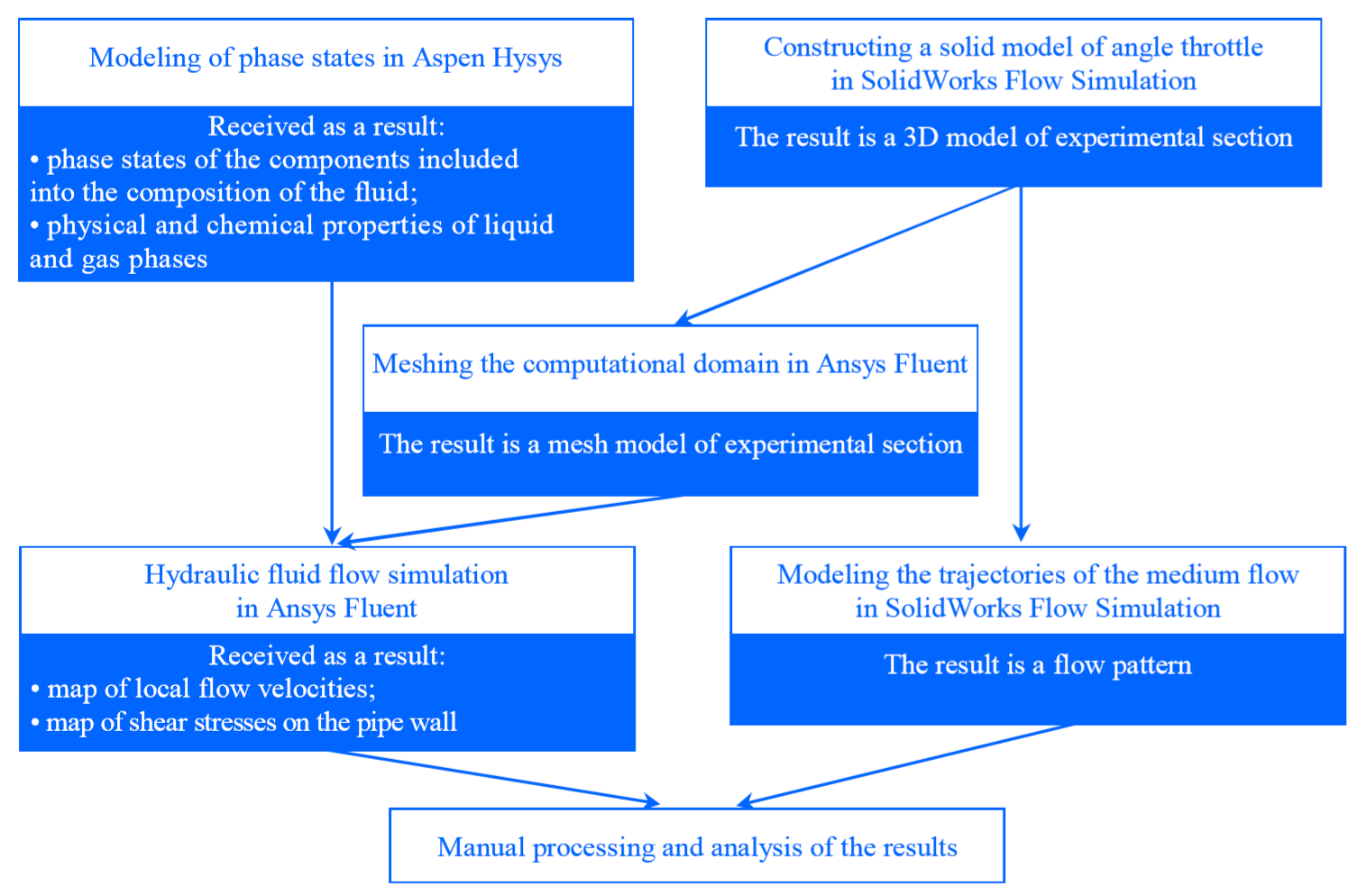
Methodology of the research. To solve stated problem, a technique to assess the influence of various factors on the rate of carbon dioxide corrosion in the pipeline section after the angle throttle was developed and applied. Brief algorithm of the technique is shown in Fig.2.
According to the developed technique, the first stage of work was the modeling of the phase states of the formation mixture for the wellhead conditions in Aspen Hysys. Considering that the extracted product is multiphase (natural gas, gas condensate, and water), the properties of the liquid and gas phases were calculated at this stage for the experimental well at the section before the angle throttle. For this, the chemical composition of the extracted fluid was set and the parameters of the well were entered. The fractional composition of the fluid was taken from the results of gas condensate investigations of the experimental well.
The narrowed component composition of the fluid with molar content, %: methane 88.921; ethane 7.050; propane 2.200; i-butane 0,283; n-butane 0,253; hydrocarbons С5 + high-boiling 0,083; nitrogen 0,222; carbon dioxide 0,980; helium 0,006; hydrogen 0,002. The calculations used a detailed componentfractional composition with boiling points up to 550 °C with an increment in fractions of 10 °C. To simplify subsequent calculations and due to the low water content (5-6 g/1000 m3 of gas) it was excluded from the chemical composition of the fluid.
The parameters of the experimental well used for calculations in the Aspen Hysys were as follows: temperature at the inlet of the angle throttle was 305.89 K; mass flow rate of fluid was 3 kg/s; the pressure at the inlet of the angle throttle was 26.9 MPa. For the calculations, the Peng – Robinson equation of state was used.

Simultaneously with the first stage, a solid model of an angle throttle and a section of pipelines after it was built. For this, the geometrical dimensions of the equipment and the pipeline were defined at the investigated well, after which a three-dimensional model of the experimental section was built in the SolidWorks Flow Simulation (Fig.3). The resulting virtual test bench allows adjusting the closing degree of the angle throttle by changing the position of the piston in the cage. The resulting model with varying degrees of closure was subsequently used for detailed calculations in Ansys Fluent.
To assess the effect of the opening/closing level of the angle throttle on the change in the trajectory of the medium inside the investigated section, the flow path was modeled in SolidWorks Flow Simulation at various operating modes of the angle throttle (10, 50 and 100 % opening). For this, the model calculation included the mass flow rate of the extracted fluid and the pressure at the inlet of the angle throttle. The multiphase flow was not taken into account, the calculation was carried out under the condition that the flow is completely single-phase, and the transported product is methane in a gaseous state.
Initial data for modeling in SolidWorks Flow Simulation: working environment was gaseous methane; opening degree of angle throttle were 0, 50, 100 %; pressure before the angle throttle was 26.9 MPa; mass flow was 3 kg/s.
The next step was a more detailed hydraulic flow modeling of the extracted product in two operating modes of the angle throttle:
• Fully opened angle throttle (pressure doesn't decrease);
• Maximum closed throttle (there is a decrease in pressure after the throttle to the required level, depending on the technological operation mode of the gas-collecting manifold, where the gas is supplied from the experimental well).
The opening/closing degree for the second operation mode of the angle throttle was determined by step-by-step changes in the opening degree on a virtual experimental test bench in SolidWorks. After constructing a geometric model in Ansys Fluent, real input parameters were set, which are fixed by control and measuring devices installed in the investigated section before the angle throttle. After performing calculations in Ansys Fluent, the obtained values of temperature and pressure in the section after the angle throttle were compared with the real values recorded by the control and measuring devices. After several iterations, the value of the opening degree for the angle throttle was obtained; it amounted to 10 %, at which the calculated values converge with the real values of the temperature and pressure parameters in the section after the angle throttle.

For detailed hydraulic modeling in Ansys Fluent, a finite-volume mesh of the computational domain was built (Fig.4). For this, a three-dimensional solid model of the experimental section was imported from the SolidWorks. The mesh was created automatically by Ansys Fluent. Moreover, the mesh was built in such a way that the closer the boundary “metal – extracted product” is, the smaller is the size of the mesh cells. As a result, the hydrodynamic calculation in the boundary zones is more accurate, and the calculation time decreases due to an increase in the size of cells located far away from the boundary layers and a decrease in the total number of cells. Polyhedrons of various configurations and different sizes were used as cells. The minimum cell volume was 5,94∙10–13, the maximum amounted to 2,45∙10–5 m3. The total number of cells, including solid and fluid, was more than 2.5 million.
The next step was the import of parameters characterizing the physical and chemical properties of the liquid and gas phases, obtained as a result of calculations in the Aspen Hysys at the first stage. The following parameters were imported as the physical and chemical properties of the gas phase: heat capacity, thermal conductivity, viscosity, molecular weight, enthalpy, entropy, critical temperature, critical pressure, critical specific volume, acentric factor. The following parameters were imported as physical and chemical properties of the liquid phase: density, heat capacity, thermal conductivity, molecular weight, and enthalpy. In addition, the liquid-gas interaction coefficient, i.e., the surface tension was imported from Aspen Hysys.
Next, the boundary conditions necessary for the calculations were set: temperature and pressure parameters in the section before the angle throttle and the values of the flow rate for liquid and gas.
Initial data for modeling in Ansys Fluent were: the working environment was a composition of real gas and gas condensate; opening degree of angle throttle amounted to 10 and 100 %; temperature before the angle throttle was 305.89 K; working pressure before the angle throttle was 26.9 MPa; mass flow rate of liquid was 0.4 kg/s; mass flow rate of gas was 2.6 kg/s.
Medium properties were calculated in Aspen Hysys using data on the fractional composition of the extracted fluid and temperature and pressure conditions during the operation.
Further calculation was performed in Ansys Fluent by the finite volume method of computational fluid dynamics. A realistic k-ɛ model of a turbulent flow for a two-phase fluid (liquid - gas) was used for the calculation.
Results. As a result of calculations in Aspen Hysys, the properties of the working medium were obtained for the real conditions of the pipeline section before the angle throttle.
Estimated properties of the gas phase: viscosity 0.0360 Pa·s; heat capacity 0,2222·104 J/(kg·K); thermal conductivity 0,0332 W/(m·K); molecular weight 0,2448·102 kg/kmol; enthalpy –7,4900× ×104 J/mol;; entropy 1,8604·102 J/(mol ·K); critical temperature 1,9056·102 К; critical pressure 4,6000 MPa; critical specific volume 0,0062 m3/kg; acentric factor 0,0110.
Estimated properties of the liquid phase in the section before the angle throttle obtained in Aspen Hysys: density 5,0730·102 kg/m3; viscosity 0,2455 Pa·s; heat capacity 0,4182·103 J/(kg·K); thermal conductivity 0,6000 W/(m·K); molecular weight 5,6580·101 kg/kmol; enthalpy –2,850× ×105 J/mol.
In addition, a parameter was obtained that characterizes the interaction of the liquid and gas phases, i.e., the surface tension, amounted to 0.0055 N/m.
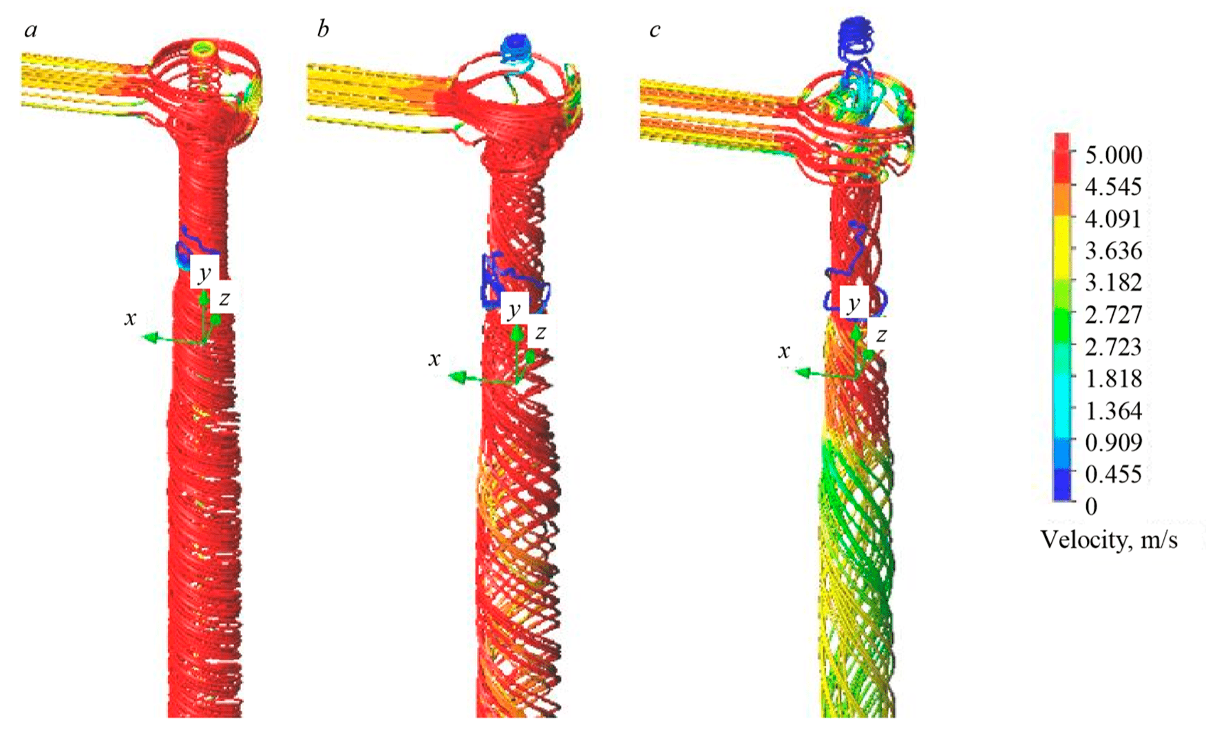
Within the framework of modeling the trajectories for the flow of medium in SolidWorks Flow Simulation, the vector field of the flow velocities in a simplified model of the working medium was obtained for several modes of opening the angle throttle (fully opened, opened by 50 and 10 %). The nature of the medium movement after the angle throttle is shown in Fig.5.
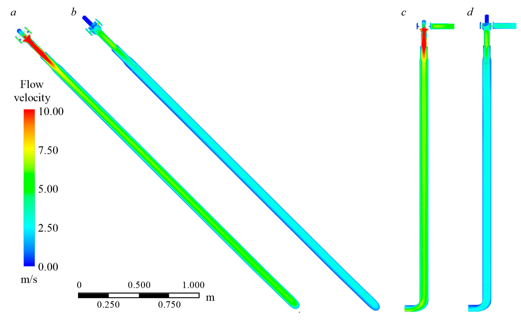
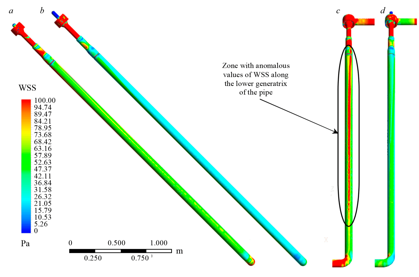
Ansys Fluent simulation resulted in maps of local velocities and WSS for two solid models: with a fully opened throttle and a throttle opened by 10 %. For a visual assessment, the most representative views of the experimental section from the side and from below are presented (Fig. 6-7).
Discussion. The performed modeling made it possible to reveal the spiral-like nature of the medium flow after the angle throttle, regardless of its opening degree (see Fig.5). The opening degree of the angular throttle only affects the velocity of the medium: the more the angular throttle is opened, the fewer the number of revolutions per unit of pipe length the working medium makes. Accordingly, it can be assumed that when the angle throttle is closed down, the value of the centrifugal force increases, and the volumetric liquid content in the near-wall zones also increases. Thus, inertial deposition of liquid on the pipe walls occurs, which subsequently enhances the corrosion processes in the places of liquid media localization. .
In addition, it was determined that when the angle throttle is closed down, due to the increase in the pressure difference, both the average flow velocity and the local values of the flow velocities increase (Fig.5, 6). However, despite the proportional increase in the flow velocity when angle throttle is closed down, the change in the WSS values is of a slightly different nature: the WSS increases unevenly, and zones with anomalous WSS values that differ from the average values along the pipe appear on the inner surface of the pipe. Figure 7 shows that a zone appears along the lower pipe generatrix (highlighted in red), in which the WSS reaches values of 100 Pa, exceeding the average WSS values by more than two times.
A possible explanation for this phenomenon is associated with the fact that simultaneously with centrifugal forces, gravitational forces impact the liquid, as a result of which the liquid flows down the walls of the pipe, and a so-called streamlet is formed on the lower generatrix. In addition, in the case of the same local flow velocities of gas and liquid, the liquid phase, due to its higher density and viscosity, creates a higher WSS than the gas.
This fact made it possible to formulate a hypothesis that intense carbon dioxide corrosion is possible in the investigated area due to an additional erosion factor arising because of the high WSS values. From a theoretical point of view, this is justified by the fact that in the process of carbon dioxide corrosion, in addition to the well-known anodic and cathodic reactions [8, 13], many secondary reactions occur, as a result of which corrosion products of various structures are formed on the metal surface [10, 16]. The resulting layer of corrosion products inhibits both the assimilation of valence electrons in the cathodic process and limits the release of iron ions into the solution during the anodic process, which reduces the corrosion rate. However, due to the high values of WSS, the film of corrosion products is constantly torn off mechanically, therefore the corrosion process in these zones constantly proceeds with a greater intensity than where the layer of corrosion products performs a protective function and WSS is not able to destroy this film mechanically.
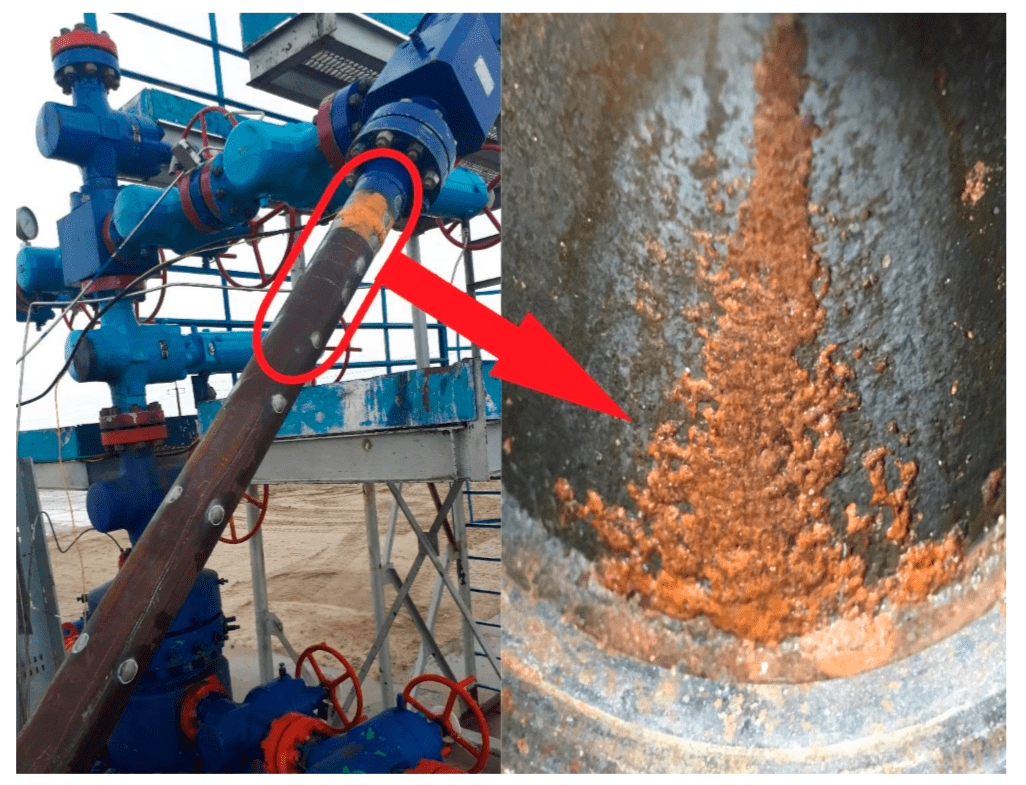
To test the hypothesis, a section of the pipeline was dismantled at the experimental well and a visual inspection of its inner surface was carried out (Fig.8). Inspection confirmed the presence of intense corrosion in the supposed zone. This damage was discovered after two years of well operation. Intense corrosion can be clearly traced along the lower pipe generatrix, which proves the influence of WSS on Vcor It is important that during the operation of the well, the angle throttle was opened by 10-20 %, and a slight final adjustment to ensure the required pressure in the gascollecting manifold was carried out by means of an automated axial pressure regulator located further in the scheme before the pipeline enters the gas-collecting manifold..
As a result of the analysis of the nature of the destruction, it is possible to draw false conclusions that the presence of water predetermines the main effect on the corrosion rate along the lower pipe generatrix. However, this conclusion has not been confirmed, because a water film is present on the entire inner surface of the pipe due to the spiral-like flow, while intense corrosion occurs only in the places of high WSS values. In addition, a visual inspection of the inner surface of the well piping was carried out when operating with a fully opened angle throttle. As a result of the inspection, no corrosion damage was revealed along the lower pipe generatrix, although this mode of operation provides a greater accumulation of liquid along the lower generatrix due to lesser flow velocities. This confirms the predominant effect of WSS on the corrosion rate in comparison with the presence of water on the pipe surface.
Accordingly, the rational operation of this pipeline section in terms of the maximum reduction in the rate of corrosion processes is to ensure the operation of the well with a fully opened angle throttle and to regulate the pressure by the existing automated axial pressure regulator located further downstream before the pipeline inlet to the gas-collecting manifold. The problem of the influence of the axial pressure regulator’s operation on Vcor is open for discussion and is not considered in this work.
The solution to the problem of reducing the corrosion effect can be either the use of a welding deposit of corrosion-resistant materials on the inner surface of the pipe, or replacing a low-alloy steel pipe with a pipe made of corrosion-resistant materials and operating the angle throttle at any opening degree. However, this technical solution requires changes in the design documentation and high CAPEX for implementation. Therefore, the optimal solution aimed at reducing the corrosion effect and not involving serious financial investments is to operate the well with a fully opened angle throttle.
Conclusion
1. A technique for predicting local zones subject to intense carbon dioxide corrosion in the piping of a gas condensate well after an angle throttle has been developed. The technique is based on a sequence of different modeling methods: modeling of the phase states for the extracted product; three-dimensional (solid-state) modeling of the investigated section; hydrodynamic flow modeling of the extracted product using the finite volume method, etc.
2. The technique has wide opportunities for visualization of the obtained simulation results, which makes it possible to analyze the effect of flow characteristics on the rate of carbon dioxide corrosion when it is impossible to conduct real experiments.
3. The technique makes it possible to predict zones of carbon dioxide corrosion localization at gas and gas condensate production facilities that have encountered manifestations of carbon dioxide corrosion and are unable to conduct real research on field equipment.
4. It is shown that the average flow velocity and its local values are not factors by which it is possible to predict the occurrence of carbon dioxide corrosion in the pipeline section after the angle throttle, and the prevailing effect on the corrosion intensity in the specified section is provided by WSS.
5. Based on the results of the work, it was recommended to operate a gas condensate well with a fully opened angle throttl.
6. Further areas of research are related to assessing the effect of the operation of an axial pressure regulator located on the production line after the angle throttle on the intensity of carbon dioxide corrosion. In addition, work will continue on studying the adhesion properties of corrosion inhibitors in pipeline sections after the angle throttle under conditions of high WSS values.
References
- Basharov M.M., Ziyatdinova A.Kh. Determination of shear stress on the wall in gas-liquid media. Vestnik IGEU. 2012. Iss. 3, p. 1-4 (in Russian).
- Voitekh N.D., Zhuravlev Yu.A., Batulin D.A. Investigation of the influence of the fluid velocity on the rate of carbon dioxide corrosion. NefteGazoKhimiya. 2013. N 1, p. 45-46 (in Russian).
- Zapevalov D.N., Vagapov R.K., Ibatullin K.A. Assessment of the internal corrosion factor at production facilities of PJSC “Gazprom” with an increased carbon dioxide content. Nauka i tekhnika v gazovoi promyshlennosti. 2018. N 3 (75), p. 59-71 (in Russian).
- Kashkovskii R.V., Ibatullin K.A. Some aspects of carbon dioxide corrosion of steel equipment and pipelines of oil and gas fields. Nauka i tekhnika v gazovoi promyshlennosti. 2016. N 3 (67), p. 71-91 (in Russian).
- Baidin I.I., Kharitonov A.N., Velichkin A.V., Ilin A.V., Podolyanskii E.S. Corrosion monitoring and organization of inhibitor protection against carbon dioxide corrosion of the low-temperature gas separation unit at the Yubileynoye oil and gas condensate field. Nauka i tekhnika v gazovoi promyshlennosti. 2018. N 2 (74), p. 49-61 (in Russian).
- Li W., Pots B.F.M., Brown B., Kee K.E., Nesic S. A Direct Measurement of Wall Shear Stress in Multiphase Flow − Is It an Important Parameter in CO2 Corrosion of Carbon Steel Pipelines. Corrosion Science. 2016. Vol. 110, p. 35-45. DOI: 10.1016/j.corsci.2016.04.008
- Ajmal T.S., Arya S.B., Udupa K.R. Effect of hydrodynamics on the flow accelerated corrosion (FAC) and electrochemical impedance behavior of line pipe steel for petroleum industry. International Journal of Pressure Vessels and Piping. 2019. Vol. 174, p. 42-53. DOI: 10.1016/j.ijpvp.2019.05.013
- De Waard C., Milliams D.E. Carbonic acid corrosion of steel. Corrosion. 1975. Vol. 31 (5), p. 177-181. DOI: 10.5006/0010-9312-31.5.177
- Hara T., Asahi H., Suehiro Y., Kaneta H. Effect of flow velocity on carbon dioxide corrosion behavior in oil and gas environments. Corrosion. 2000. Vol. 56. N 8, p. 860-866. DOI: 10.5006/1.3280589
- Kahyarian A., Nesic S. A new narrative for CO2 corrosion of mild steel. Journal of the Electrochemical Society. 2019. Vol. 166. N 11. DOI: 10.1149/2.0071911jes
- Kahyarian A., Singer M., Nesic S. Modeling of uniform CO2 corrosion of mild steel in gas transportation systems: A review. Journal of Natural Gas Science and Engineering. 2016. Vol. 29, p. 530-549. DOI: 10.1016/j.jngse.2015.12.052
- Koriakin A. Carbon dioxide corrosion at the objects of the second district of Achimovsk deposits of Urengoy oil and gas bearing complex. International Journal of Mechanical Engineering and Technology. 2018. Vol. 9. Iss. 8, p. 1073-1080.
- Nešić S. Carbon dioxide corrosion of mild steel. Uhlig’s Corrosion Handbook. Ed. by R.Winston Revie. Hoboken, New Jersey: John Wiley & Sons, 2011, p. 229-245. DOI: 10.1002/9780470872864.ch19
- Nešić S. Key issues related to modelling of internal corrosion of oil and gas pipelines – A review. Corrosion Science. 2007. Vol. 49. Iss. 12, p. 4308-4338. DOI: 10.1016/j.corsci.2007.06.006
- Nyborg R. Guidelines for prediction of CO2 corrosion in oil and gas production systems; Institute for Energy Technology, 2009, p. 9.
- Tran T., Brown B., Nešić S. Corrosion of Mild Steel in an Aqueous CO2 Environment – Basic Electrochemical Mechanisms Revisited. Conference Paper: Corrosion, 15-19 Marсh 2015, Dallas, Texas, p. 1916-1926. NACE-2015-5671.
- Utanohara Y., Murase M. Influence of flow velocity and temperature on flow accelerated corrosion rate at an elbow pipe. Nuclear Engineering and Design. 2019. Vol. 342, p. 20-28. DOI: 10.1016/j.nucengdes.2018.11.022
- Yusupov A. Mathematical simulation of the rate of carbon dioxide corrosion at the facilities of Gazprom dobycha Urengoy LLC. E3S Web of Conferences. Vol. 121. I International Conference “Corrosion in the Oil and Gas Industry 2019”. DOI: 10.1051/e3sconf/201912101019