
Study of drive currents for lifting bridge cranes of metallurgical enterprises for early diagnosis of load excess weight
- 1 — Dr.Habil. Sevastopol State University ▪ Orcid ▪ Elibrary ▪ Scopus ▪ ResearcherID
- 2 — Ph.D. Siberian State Industrial University ▪ Orcid ▪ Elibrary ▪ Scopus
- 3 — Joint Stock Company “Siberian Tyazhpromelektroprojekt” ▪ Orcid ▪ Elibrary

Abstract
The article discusses an approach based on the analysis of the drive motor currents to create an additional means of protection against emergency situations during the operation of bridge cranes associated with lifting a load with a mass exceeding the permissible one. A mathematical model of an overhead crane drive is described, as well as the results of computer simulation. It is shown that in the process of lifting up, before the stage of lifting the load, the stator current of the drive electric motor does not depend of the load mass, but when the load is detached, already for several periods of the mains voltage after the rope is pulled, when the mass of the load is exceeded, a measurable excess of the amplitude value of the current is recorded. This pattern has been confirmed for a number of cranes of various lifting capacities used at metallurgical enterprises. The possibility of diagnosing excess weight of the lifted load with a higher speed than existing mechanical methods of overload control is demonstrated, at the same time it is not required to make changes to the structural elements of overhead cranes.
None
Introduction. The main types of technological and repair equipment at metallurgical enterprises include lifting mechanisms: bridge cranes and cranes for various purposes. The specific weight of lifting mechanisms in the technological and repair equipment of shops of metallurgical enterprises can reach 10-13 %. Accidents associated with the use of lifting equipment often leads to injury to people in the danger zone [3]. In addition, the rhythm of technological processes and high economic indicators of enterprises depend on the reliable operation of lifting mechanisms. Therefore, the provision of lifting mechanisms with modern high-speed protection against emergency situations and diagnostic tools is an urgent task [5, 14, 15].
For bridge cranes of metallurgical enterprises, the following emergency situations are standard: over-lifting of the load-gripping body, violation of the integrity and geometry of the crane structural elements, breakage of hoisting ropes, overheating and failure of the lifting electric motor. An increase in the crane load when lifting a load of an unacceptable mass can lead to the listed emergencies.
To protect against accidents caused by the lifting of loads of unacceptable mass, load limiters are used. Currently, several methods of overload control are used, including devices using spring-lever systems [6] and devices using strain gauges [8, 9], кwhich, however, do not have sufficient accuracy, sensitivity and speed. Also, protection schemes have been developed with the use of additional power elements, however, they complicate the design of lifting mechanisms, thereby reducing the reliability of protection [7].
Taking into account the above, as well as in the conditions of the repair and operating units personnel reduction, to recognize the emergency excess of the weight of the cargo, it is necessary to use additional capabilities, including methods of indirect control. For indirect control of the equipment of mining and metallurgical enterprises, methods based on the analysis of changes over time in the parameters of the working cycle [1], including the analysis of the dynamic state of drive motors are used [11, 12].
There are methods for indirect control of the mass of the load to control and protect crane equipment during the lifting process for cranes for other purposes. Thus, in sources [21, 23, 32] monitoring and diagnostics systems are offered for mobile, tower and bridge cranes, respectively, providing additional information about the crane operation to its operator. However, all these systems for determining the mass of the load involve the use of additional sensors in the crane structure – encoders, strain gauges. The article [24] describes a control system for a harbor crane with a built-in load mass estimation loop, for the operation of which additional load displacement sensors are used relative to the boom lifting block, but it does not assume the possibility of rope slack. The article [28] shows a control system for a crane of a drilling platform, in which the mass of the load is calculated from the data of the hoisting rope strain gauge and the hydrodynamic pressure sensor. Articles [30, 31] consider an overload protection system when lifting for cranes for marine use as part of a forward control system, for the operation of which a dynamic model of a traction winch servo motor and a lifting mechanism with a load are used together, however, the design differences do not allow transferring this approach to bridge cranes of metallurgical enterprises.
Protection systems against excess cargo weight using indirect control methods for crane mechanisms are actively used, however, currently there is no effective approach for bridge cranes, which does not require the installation of additional sensors in the mechanical subsystem of the crane, but uses information about the dynamic state of electric motors.
Formulation of problem. To create an additional means of preventing accidents – lifting loads of unacceptable mass – using the control of the electric motor currents of the overhead crane lifting mechanism, it is necessary to analyze its dynamic state, and when analyzing the dynamic modes of electric drives of mining and metallurgical equipment, it is necessary to take into account the dynamics of the mechanical subsystem [4,]. A number of mathematical models have been developed for lifting mechanisms for overhead cranes that describe dynamic modes and processes in units and elements of equipment [2, 19, 22, 27]. However, these models are very complex and therefore are not suitable for solving the problem, assuming in the future the need for technical implementation in the form of software and hardware, for which a relatively simple model with lumped parameters is needed, but adequately describing the technological operation of lifting a load by a crane and allowing to reliably identify an emergency situation of excess cargo weight.
The operation of lifting the load consists of three consistent stages, namely, the choice of the rope weakness until the tension force appears in it, the rope tension until the weight of the load is balanced by the force in the rope and the load lifting off with its subsequent rising. An important feature of the rope slack selection stage is the actual absence of mutual connection between the load and the drive motor before the tension force appears in the rope. This means that it is possible to diagnose an emergency excess of the load weight by an indirect method only as a result of a detailed analysis of the hoist drive electric motor mathematical model and crane mechanism during the transition from the first stage to the second and third, during which it is necessary to identify diagnostic signs of the mode of lifting a load of excessive weight.
Methodology. For the mathematical description of the drive mechanism for lifting bridge cranes, the most common in practice is the model of a three-mass mechanical system with elastic connections between the masses [25], shown in Fig.1, where m1, m2, m3 – the masses of the rotating parts of the hoist mechanism, load and bridge reduced to the rope; x1, x2, x3 – displacement of masses; C1, C2 – stiffness of the rope and crane bridge; l – rope slack; P – starting force of an electric motor, defined as the product of the electromagnetic moment on the motor shaft M by the reduction coefficient Kp = i/Rbar; F – rope tension.
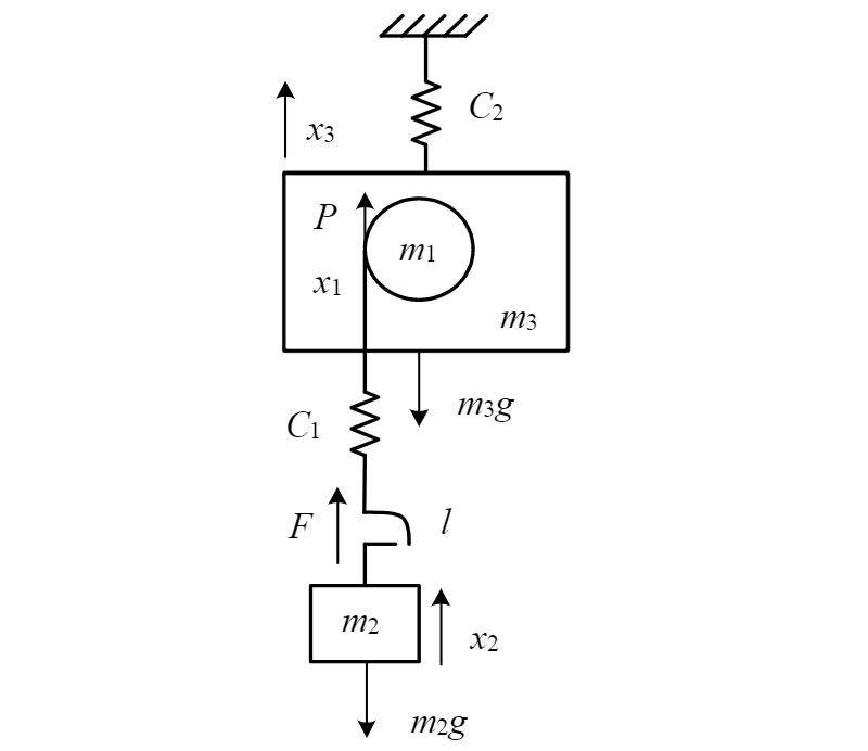
Based on this model, systems of differential equations are compiled that describe the system at the stages of choosing the rope slack, its tension and the separation of the load from the support [25]. Sequential modeling each of the stages, taking into account the initial conditions during the transition from one to the other, makes it possible to adequately describe the dynamic state of the drive mechanism for lifting bridge cranes, and the conditions for the beginning and end of the stages are given in the table.
Conditions for the beginning and end lifting mechanism movement stages
| Stage | Initial conditions | End conditions |
| 1. Slack rope selection | $$ \begin{array} [c]{ll} x_1=0; \ x_2=0; \ x_3=0; \\ x_1^{'}=0; x_2^{'}=0; x_3^{'}=0; t=0; \end{array} $$ | $$ \begin{array} \biggl\ \begin{cases} x_{1}=l; \\ F=C_1(x_1-l)>0; \end{cases} \\ x_{11k}=x_1; \ x_{21k}=0; \ x_{31k}=x_3; \\ x_{11k}^{'}=x_1^{'}; \ x_{21k}^{'}=0; \ x_{31k}^{'}=x_3^{'}; \ t=t_{1k}.\end{array} $$ |
| 2. Tensioning the rope until balancing | $$ \begin{array} [c]{ll} x_1=x_{11k}; \ x_2=x_{21k}; \ x_3=x_{31k}; \\ x_1^{'}=x_{11k}^{'}; x_2^{'}=x_{21k}^{'}; x_3^{'}=x_{31k}^{'}; t=t_{1k}; \end{array} $$ | $$ \begin{array} [c]{ll} F=C_1(x_1-x_2)=m_2g; \\ x_{12k}=x_1; \ x_{22k}=0; \ x_{32k}=x_3; \\ x_{12k}^{'}=x_1^{'}; \ x_{22k}^{'}=0; \ x_{32k}^{'}=x_3^{'}; \ t=t_{2k}.\end{array} $$ |
| 3. Cargo lift-off with following lifting up | $$ \begin{array} [c]{ll} x_1=x_{12k}; \ x_2=x_{22k}; \ x_3=x_{32k}; \\ x_1^{'}=x_{12k}^{'}; x_2^{'}=x_{22k}^{'}; x_3^{'}=x_{32k}^{'}; t=t_{2k}; \end{array} $$ | - |
The motion of the masses of a three-mass mechanical system after separation of the load is described by the following system of equations:
For subsequent analysis, it is convenient to reduce the system of equations to a linear form by performing the change of variables:
This system of equations shows that the electromagnetic moment of the engine M and the load mass m2 during the transition to the stages of tensioning the rope and detaching the load turn out to be dynamically connected, which means that the analysis of the quantities affecting the electromagnetic moment at this stage is able to reveal diagnostic signs of the mode of lifting a load of excessive mass.
The system of equations (2) can be solved by various methods. Since modern diagnostic systems are technically implemented on the basis of microcontroller devices, which are characterized by time quantization of signals, it is convenient to reduce the system of equations (2) to a discrete form. To perform sampling, the Laplace transform and the bilinear transform (Tustin transform) are used sequentially.
After passing from the space of originals to the space of the complex variable p, performing the Laplace transform, and then from it through the bilinear transformation to the variable z, we obtain the following discrete model:
The system of equations (3) should be solved together with the mathematical model of the electric drive, including the overhead crane as part of the electromechanical complex [13]. An asynchronous motor-based drive is considered as an electric drive.
Several approaches can be used to compile a mathematical description of an induction motor [16, 17, 26, 29]. One of them is modeling in phase coordinates, which is most suitable for diagnostics tasks, since it is more suitable in the event of malfunctions of the engine itself.
An induction motor in phase coordinates a, b, c An induction motor in phase coordinates [20]:
where UA, UB, UC – voltage at the terminals of the stator winding; ΨA, ΨB, ΨC, iA, iB, iC – active resistances of stator phase windings; rA, rB, rC – flux linkage and currents of the rotor phase windings; Ψa, Ψb, Ψc, ia, ib, ic – потокосцепления и токи обмоток фаз ротора; ra, rb, rc – active resistances of the rotor phase windings; γ – rotor angular position; WEM – supply of electromagnetic energy of the machine; p – number of pole pairs; ωr – rotor velocity; ωs – synchronous frequency of stator field rotation.
The flux linkage of the stator and rotor windings is described by the following equations:
where LA, LB, LC – stator phase inductances; La, Lb, Lc – rotor phase inductances; MAB, MBC, MAC – mutual inductances between stator windings; Mab, Mbc, Mac – mutual inductance between the rotor windings.
Since the stator and rotor windings move relative to each other with a frequency ωrr, the mutual inductances between the windings are determined by harmonic dependences [20], where MAam, MBbm, MCcm – maximum values of mutual inductance when the rotor windings pass the phases a, b and с respectively, exactly under the stator windings of the phases А, В and С. For example, for the phase А:
As a result, the differential three-phase model of an asynchronous electric motor in natural phase coordinates, obtained from the system of equations (4), looks as follows:
where the derivatives of the flux linkages dependent on the angle γ are determined by differentiating the system of equations (5) with respect to time as a complex function taking into account the harmonic dependences of the mutual inductance (6) for phase А and similar ones for phases В and С.
The system of equations (7), similar to the model of a three-mass mechanical system, can be conveniently presented in discrete form by means of a bilinear transformation [10]:
where the matrices of voltages and currents are following:
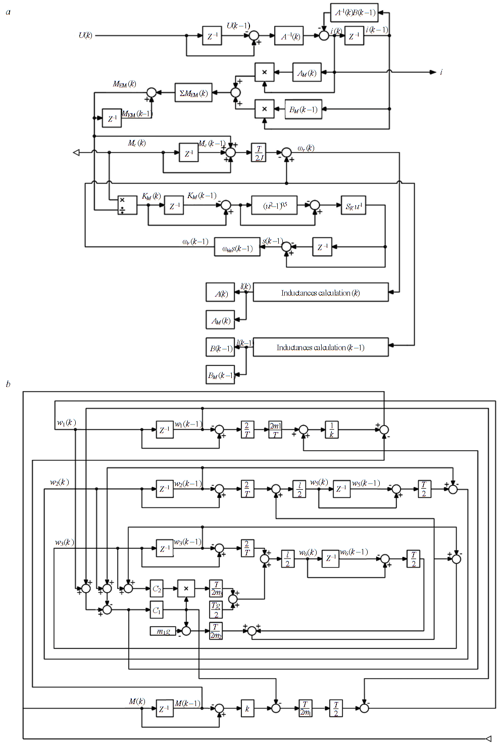
The analytical solution of Cauchy problems for the stages of lifting a load using the obtained description of an electric motor and a three-mass mechanical system seems to be difficult due to the presence of a large number of variables, as well as the derivative with respect to the rotor rotation angle, and therefore the obtained mathematical description was analyzed by the method of computer simulation in the Matlab Simulink software package [18]. An overhead crane hoist drive model corresponding to equations (2)-(9) is shown in Fig.2.
Discussion. Let us show the use of the model shown in Fig.2 for calculating the stator currents of the motor of the lifting mechanism of a repair bridge crane with a lifting capacity of 32 tons. The system was simulated in the modes of lifting a load with a nominal mass and lifting a load with a mass exceeding the permissible by 3, 15 and 25 %, respectively, consequently, with the computational experiments as the mass of the cargo m2 in the system of equations (3), the following values were set: mI = 32000 kg, mII = 33000 kg, mIII = 36000 kg and mIV = 40000 kg; the value of the rope slack l is assumed to be the same for all loads. As the results of modeling, the values of the stator currents of the lifting electric motor were obtained when lifting from the surface of the weights (Fig.3).
Analyzing the results obtained, it can be noted that in the system under consideration, until the time t = 4,8 s , the rope slack is selected, as a result of which the stator current is the same for all weights, and its amplitude does not change during the entire stage.
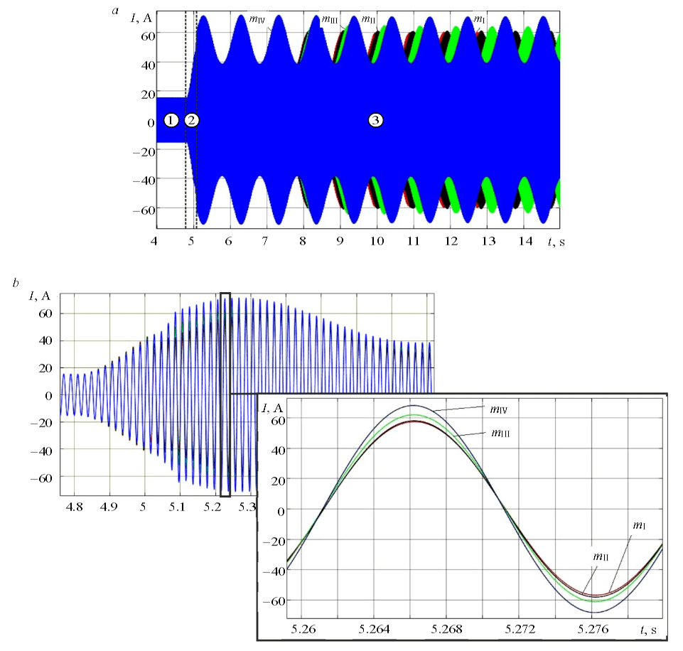
After the first stage of lifting the load ends, a force arises in the rope, and the value of the current increases with an increase in the rope tension of the lifting mechanism. The condition for the end of the second stage is the equality of the load weight in the rope, as a result of which the end time of the second stage for each of the loads is different, and the division in Fig.3, а is shown conditionally. For cargo with a larger mass, the duration of the second stage increases.
At the third stage of lifting the load, the amplitude values of the current fluctuate with a frequency determined by the ratio of the reduced masses and the stiffness of the connections. In addition to changing the time of the beginning of the stage of lifting the load, the amplitude values of the current for different masses also differ, and there is also a shift of oscillations in phase for loads of different masses.
The simulation results show that already in the first five periods of the mains voltage after separation of the load from the supporting surface, a fixable difference in the amplitude of the stator current is found (Fig. 3, b), which for mII is 1,8 %, for mIII – 12,7 %, and for mIV – 23,6 %. The appearance of differences in the magnitudes of the stator current amplitude indicates the sensitivity of the model to variations in the mass of the lifted load and confirms the possibility of diagnosing overload for units of periods of the mains voltage.
Various weights lifting loads processes simulation, similar to that shown above, was done for a number of cranes of various lifting capacities used at metallurgical enterprises. The equipment park of the company JSC “EVRAZ VPSS (Volzhsky Plant of Steel Structures)” (Novokuznetsk), numbering 354 units of overhead cranes, was considered as a basis. As a result of his analysis, the series of overhead cranes under consideration included 51 units of standard sizes with a drive power of 5-160 kW and a weight of the lifted load of 5-200 tons.
Using the systems of equations (2)-(9) and the model shown in Fig.2, the values of the stator currents of asynchronous motors of lifting mechanisms for all bridge cranes of the series under consideration were determined. For each of the standard sizes, a simulation of the overload situation of the lifting mechanism with a load mass exceeding the nominal by 1 % was performed. The values of the stator phase current were determined in the first half-period of the supply network voltage when the load was detached, and in all cases an increase in its amplitude was recorded relative to the experience of lifting with a load of nominal mass with a weighted average deviation value of 0.579 % over the series. For the obtained simulation results, statistical relationships were investigated between the drive power N, the crane lifting capacity W, an increase in the current amplitude I and regression equations were obtained with a linear correlation coefficient of 0.75:
Additional studies have shown that the increase in the stator current amplitude from the first to the fifth period of the mains voltage is linear, as is the increase in the stator current amplitude with an increase in mass from 1 to 10 %.
Thus, the regression equations (10) make it possible to predict an increase in the amplitude of the stator current when the weight of the load is exceeded for bridge cranes that are not included in the considered list of standard sizes, and, therefore, serve as the basis for an algorithm for early diagnosis of excess weight of the load for any bridge crane metallurgical enterprises and can be used in the future to determine the setting for the operation of software and hardware protection.
Conclusion. The results of all computational experiments confirmed the following:
• at the stage of choosing the slack in the rope, the stator current of the electric motor of the lifting mechanism does not depend on the mass of the load;
• the time before the start of the third stage increases with the increase in the weight of the cargo;
• peak current values at the stage of lifting the load increase with increasing mass of the load, and a fixable difference appears already after five periods of mains voltage from the beginning of the stage;
• the frequency of current fluctuations after detachment of the load depends on its mass, but varies within small limits.
The volume of the results obtained made it possible to determine the statistical relationships between the values of the hoist drive power, the lifting capacity of the overhead crane and the deviations in the amplitude of the electric motor current, which are the basis for the algorithm for early diagnosis of excess weight of the load. Thus, monitoring the current of the hoist electric motor allows us to create protection of the hoisting mechanism from exceeding the weight of the load, which does not require changes to the structural elements of overhead cranes. The speed of the proposed approach is significantly higher than that of the existing mechanical methods of overload control.
References
- Afanasev A.S., Tret'yakova A. A. Method of diagnostics of diesel engines in timing of the operating cycle. Journal of Mining Institute. 2015. Vol. 214, p. 51-56 (in Russian).
- Akhtulova L.N., Akhtulov A.L., Kirasirov O.M., Mashonskii V.A. Visual modeling of a double-girder overhead crane as a complex dynamic system. Omskii nauchnyi vestnik. 2014. N 1(127), p. 147-152 (in Russian).
- Goldobina L.A., Demenkov P.A., Trushko O.V. Ensuring the Safety of Construction Works During the Erection of Buildings and Structures. Journal of Mining Institute. 2019. Vol 239, p. 583-595. DOI: 10.31897/pmi.2019.5.583
- Eshchin E.K. Calculations of dynamic operating modes of electric drives of self-propelled mining machines. Journal of Mining Institute. 2018. Vol 233. p. 534-538. DOI: 10.31897/pmi.2018.5.534
- Izvekov Yu.A., Gugina E.M., Anisimov A.L., Shemetova V.V. Risk assessment of potentially dangerous metallurgical objects outside the warranty service life in quality management of the industrial enterprise. Modern high technologies. 2018. N 11 (Part 2), p. 179-182 (in Russian).
- Platonov G.G., Kudryavtsev A.V., Sologubov S.N. Patent № 2144901 RF. Device for measuring and limiting the lifting ca-pacity of the winch. Publ. 27.01.2000. Bul. N 3 (in Russian).
- Kadyrov Kh.M. Patent № 2381984 RF. Device for determining the weight of the load of an overhead crane. Publ. 20.02.2010. Bul. N 5 (in Russian).
- Potapov V.A., Timin Yu.F., Kornikov M.V. Patent № 2464220 RF. Strain gauge axle for measuring the load on the hook of a crane. Publ. 20.10.2012. Bul. N 29 (in Russian).
- Korovin V.A., Korovin K.V. Patent № 2483016 RF. Overhead crane load limiter. Publ. 27.05.2013. Bul. N 15 (in Russian).
- Polishchuk V.I. Development of the theory of constructing diagnostic systems for synchronous machines: Avtoref. dis. … d-ra tekhn. nauk. Samara: Camarskii gosudarstvennyi tekhnicheskii universitet, 2016, p. 36 (in Russian).
- Savelev A.N., Kipervasser M.V., Anikanov D.S. The assessment of power changes in motor parameters in case of emergencies in the mechanical part of belt conveyor. Izvestiya vysshikh uchebnykh zavedenii. Ferrous Metallurgy. 2015. Vol. 58. N 12, p. 906-911. DOI: 10.17073/0368-0797-2015-12-906-911 (in Russian).
- Safin N.R., Prakht V.A., Dmitrievskii V.A. Fault diagnosis of fan units using spectral analysis of stator currents. Energobezopasnost i energosberezhenie. 2016. N 4, p. 37-42. DOI: 10.18635/2071-2219-2016-4-37-42 (in Russian).
- Semykina I., Kipervasser M., Gerasimuk A. Study of the transient process in the circuit in case of turbocompressor multiplier defect and development of system structural scheme to discover multiplier defect. Vestnik Chuvashskogo Universiteta. 2017. N 3, p. 138-144 (in Russian).
- Turysheva E.S. Improvement of the process of automatic protection of a hydraulic crane from overload and overturning: Avtoref. dis. … kand. tekhn. nauk. Krasnoyarsk: Sibirskii federalnyi universitet, 2009, p. 18 (in Russian).
- Abdel-Rahman E.M., Nayfeh A.H., Masoud Z.N. Dynamics and Control of Cranes: A Review. Journal of Vibration and Control. 2003. Vol. 9(7), p. 863-908. DOI: 10.1177/1077546303009007007
- Ansari A., Deshpande D. Mathematical Model of Asynchronous Machine in Matlab / Simulink. International Journal of Engineering Science and Technology. 2010. Vol. 2(5), p. 1260-1267. DOI: 10.1.1.165.5447
- Arya M.K. Transient Analysis of Three Phase Squirrel Cage Induction Machine using Matlab / M.K.Arya, S.Wadhwani. In-ternational Journal of Engineering Research and Applications. 2009. Vol. 1. Iss. 3, p. 918-922. DOI: 10.1.1.300.1599
- Chee-Mun Ong. Dynamic simulation of electric machinery using Matlab / Simulink. Prentice Hall PTR, 1997, p. 626.
- Chmurawa M., Gąska D. Modeling of bridge cranes for dimensioning needs of their load-carrying structures. The Interna-tional Journal of Ingenium. 2005. Vol. 4, p. 409-414.
- Kirtley J.L., Beaty H.W., Ghai N.K., Leeb S.B., Lyon R.H. Electric Motor Handbook. New York, USA: McGraw-Hill Ed-ucation, 1998. p. 400.
- Fang Y., Cho Y.K., Chen J. A framework for real-time pro-active safety assistance for mobile crane lifting operations. Au-tomation in Construction. 2016. Vol. 72. Part 3, p. 367-379. DOI: 10.1016/j.autcon.2016.08.025
- Gąska D. Numeryczno-statystyczna metoda oceny nośności i stateczności stalowych ustrojów nośnych dźwignic: Praca doktorska. Katowice: Politechnika Śląska, 2007, p. 204.
- Gu Liang-Yao, Yang Yue, Chen Feng. Research on intelligent monitoring and protection system of distributive multi-tower cranes. International Conference on Computer Application and System Modeling, 2010, October 22-24, Taiyuan, China. IEEE, 2010, p. 540-543. DOI: 10.1109/ICCASM.2010.5623149
- He Wei, Shuang Zhang, Shuzhi Sam Ge Adaptive Control of a Flexible Crane System With the Boundary Output Constraint. IEEE Transactions On Industrial Electronics. 2014. Vol. 61. Iss. 8, p. 4126-4133. DOI: 10.1109/TIE.2013.2288200
- Hong K.-S., Shah U.H. Lumped mass models of mobile cranes. Dynamics and Control of Industrial Cranes: Advances in Industrial Control. Singapore: Springer Nature Singapore Pte Ltd, 2019, p. 49-65. DOI: 10.1007/978-981-13-5770-1_4
- Krishnan R. Electric Motor Drives: Modelling, Analysis and Control. New Jersy, USA: Upper Saddle River, 2001, p. 626.
- Matyja T., Sładkowski A. Modeling of the Lift Crane Vibration Caused by the Lifting Loads. Zdvihací Zařízení v Teorii a Praxi, 2007, April 10-11, Brno, Czech Republic. VUT Brno, 2007, p. 98-105.
- Messineo S., Serrani A. Offshore Crane Control Based on Adaptive External Models. Automatica. 2009. Vol. 45. Iss. 11, p. 2546-2556. DOI: 10.1016/j.automatica.2009.07.032
- Liang T., Zhou N., Lu T., Wu H., Ju P. Parameter Imputation Methods and Typical Parameter Analysis of Load Transient Model of Induction Motor. Dianli Xitong Zidonghua – Automation of Electric Power Systems. 2020. Vol. 44. N 1, p. 74-82. DOI: 10.7500/AEPS20190507002 (In Chinese).
- Ren Z., Skjetne R., Gao Z. A Crane Overload Protection Controller for Blade Lifting Operation Based on Model Predictive Control. Energies. 2019. Vol. 12(1), p. 1-22. DOI: 10.3390/en12010050
- Ren Z., Skjetne R., Gao Z. Modeling and Control of Crane Overload Protection During Marine Lifting Operation Based on Model Predictive Control. International Conference on Ocean, Offshore and Arctic Engineering, 2017, June 25-30, ASME, Trondheim, Norway. 2017. Vol. 57779, p. 9. DOI: 10.1115/OMAE2017-62003
- Szpytko J. Control and Fault Diagnosis System of Crane Operation. IFAC Proceedings Volumes. 2001. Vol. 34. Iss. 17, p. 237-242. DOI: 10.1016/S1474-6670(17)33286-X