
Development of equipment and improvement of technology for inertial thickening of backfill hydraulic mixtures at the final stages of transportation
- 1 — Postgraduate Student Empress Catherine II Saint Petersburg Mining University ▪ Orcid ▪ Scopus
- 2 — Ph.D., Dr.Sci. Associate Professor Empress Catherine II Saint Petersburg Mining University ▪ Orcid
Abstract
The results of the study of the functioning of the developed thickening equipment as part of the stowing complex for the formation of a flow of high-concentration hydromixture are presented. To explain the operation of the hydrotransport system of the stowing complex, equipped with a thickener of the developed design, its basic diagram is presented. A mathematical model has been created that describes the mechanism of inertial sedimentation of a solid component of a hydraulic mixture in a working chamber equipped with hydrodynamic profiles. Interaction with the profile leads to flow stratification due to a change in the trajectory of movement and a decrease in speed. The interval of rational velocity of primary pulp entering the input of the working chamber of the inertial thickener is substantiated. The synthesis of solutions of the thickening process model is performed in the COMSOL Multiphysics and Ansys Fluent programs. This made it possible to eliminate physical contradictions in the operation of the equipment and justify the overall dimensions of its main elements, ensuring the implementation of the mechanism of inertial sedimentation of the slurry. It was found that the concentration of the thickened flow at the outlet branch pipe of the thickener working chamber is determined by the level of the primary hydraulic fluid velocity, the characteristic length of the section of interaction with the deflecting profile, and the ratio of the flow and attack angles. A nomogram of the dynamics of the change in the hydraulic fluid concentration in the section of the outlet branch pipe depending on the ratios of the overall dimensions of the deflecting profile of the working chamber was compiled. The results of the study allowed formulating recommendations for selecting the dimensions of the thickener's deflecting hydrodynamic profile to form a flow of hydraulic mixture with a concentration of about 50 % by weight. The developed equipment can be used in a stowage complex and will increase the range of supply of the stowage mixture. This is due to the fact that a flow of primary slurry with a low concentration, due to lower pressure losses, can be moved in a pipeline system over a greater distance than a flow with a high filler content. The use of a thickener at the final stage of transportation is intended to increase the concentration of the hydraulic mixture immediately before production.
None
Introduction
The objectives of mining production and technologies related to hydraulic transport of mineral processing products include reducing energy costs, decreasing the energy intensity of technological processes and using waste-free technologies [1-3]. This is achieved by using underground mining systems with backfilling of mined-out spaces and using production waste [4, 5]. Filling the mined-out space is intended to ensure its geomechanical stability [6, 7].
Most mining enterprises use both dry and hydraulic mixtures for backfilling with the use of enrichment waste. In the last 20-25 years, the use of hydraulic mixtures in backfilling operations has reached 85 %, while dry backfilling is used in only 15 % of cases [8, 9]. Backfilling operations with dry mixtures are carried out mechanically [10]. The material is transported by drift belt conveyors, and then delivered to the mined-out space by self-propelled cars [11]. Hydraulic mixtures are delivered to the mined-out space through a system of backfill pipelines under natural pressure, determined by the ratio of the lengths of the vertical and horizontal sections [12]. Pressure losses due to overcoming local resistance and linear pressure losses significantly limit the distance of transportation of hydraulic mixtures. To increase the supply range, mixtures with a high content of the carrier medium are used, pipes with low specific roughness are used, which reduce the contact friction of the flow on the working surfaces [13, 14]. Additionally, auxiliary equipment is required, for example, vibration activators, slurry pumps [15, 16].
In the preparation of the hardening backfill, only inorganic binders are used [17]. In the mining industry, many of the known binders are used: cements, lime, gypsum, anhydrite, ground granulated slags, boiler ash, pyrrhotite-containing tailings of processing plants, etc. [18-20]. Complex binders are used more often – various cements, the main component of which are silicates and calcium aluminates formed during high-temperature processing of raw materials, for example, at the Verkhnekamsk deposit, Tashtagol mine, Taimyr mine, etc. One of the most effective types of raw materials for the production of local binders for the hardening backfill is blast furnace granulated slag. They are silicate and aluminosilicate melts obtained during the smelting of iron.
According to the study [11], an artificial massif formed from a hydraulic mixture based on enrichment waste is subject to less deformation compared to an artificial massif formed from dry backfill material. This helps to minimize the subsidence of the artificial massif and subsequent disturbances of the workings [21, 22]. One of the main requirements for hydraulic backfill is to ensure the strength of the formed backfill massif, achieved by it during the hardening process, simultaneously with the separation of the carrier liquid and a decrease in humidity [23-25].
A typical roof management passport contains information on the sequence of work, as well as data on the brands of backfill mixtures used to form the bottom layer of the backfill in each of the backfill sections. The mixture is often supplied to the backfill workings through backfill wells and concrete pipelines. Water released from the backfill mixture is discharged by pumps and rubber hoses into a water-bypass well. High-quality installation of a concrete pipeline, an insulating bulkhead, and constant monitoring along the backfill mixture supply route prevent the backfill mixture from getting into active mine workings.
Methods
The rheological properties of the hardening mixtures must ensure stable, stratification-free transportation along the filling pipeline route, uniform, stratification-free spreading throughout the chamber, and the required depth of penetration into the rock when using a combined chamber filling method. The strength and compression properties of the constructed artificial massif must comply with the accepted standard indicators.
Mixtures with a high content of dispersed fraction allow to significantly reduce water
infiltration, reducing flooding of workings and the risk of their subsequent violations. To reduce shear stress during movement of the backfill mixture, the content of the solid phase of about
45 μm in size should be no more than 15 %. Hydraulic mixtures of dispersed substances are dilatants. Due to the internal structure and intermolecular interaction, during which the dispersed phase is structured in a specific volume, a power-law dependence of the change in shear stress
on the velocity gradient is observed. The flow movement obeys the Ostwald – de Waale rheological law [26]:
where K – coefficient of viscosity of a liquid; n – a nonlinearity index that characterizes the degree to which the behavior of a fluid deviates from Newtonian behavior.
The change in the exponent of the power dependence affects the form of the rheological curve. At n < 1, the liquid “liquefies” under shear, which corresponds to Bingham bodies and viscous-plastic liquids (Shvedov bodies). This can be traced, for example, in paraffinic oils or petroleum products at temperatures close to the freezing point. At n > 1, on the contrary, an increase in the resistance of the substance under shear is observed (suspensions of enrichment tailings, pastes) [5, 27]. This statement is consistent with what is observed with an increase in the content of the dispersed phase, leading to an increase in the value of n, an increase in the linear losses of the flow pressure. This is a consequence of the fact that in structured substances an increase in concentration and a decrease in size lead to the appearance of additional contact friction between the particles of the flow [28]. To take into account the total stress required to initiate fluid motion (overcoming the yield point), it is permissible to use a modified power law – the Herschel – Bulkley model [29, 30].
The interaction of solid particles in a slurry flow depends on their size, shape, and concentration in the slurry. Small particles form dense mixtures, and their effect on the liquid phase is determined by the concentration in the flow. Larger particles form mixtures with a high concentration in the core of the flow [19]. In this case, significant differentiation by the size of the dispersed medium leads to a violation of the homogeneity of the flow and a change in its rheological characteristics. To ensure the stability of the granulometric composition, fine grinding mills and disintegrators are used [31]. The positive effect of using such equipment is due to the fact that crushing of solid materials by a highly loaded impact occurs in places of fusion, structural defects and stress concentrators in the fraction of dispersed material. This allows for a more uniform form of the fraction, as well as minimizing its secondary destruction during transportation.
When the speed of the hydraulic mixture changes, the thickness of the bottom moving layer with a high concentration of the solid phase changes. The moving layer affects the flow of the hydraulic mixture similarly to the walls of a pipe with a high roughness of the working surface. The thickness, density and speed of movement of this layer depend on the average speed of the flow of the hydraulic mixture and the size of the solid phase. As the speed of the flow decreases, the concentration of solid particles in a suspended state decreases, while the thickness of the layer formed by them increases, turning into sediment [32].
To improve the quality of the filling mixture, the most common methods are the use of binders, as well as the use of thickening equipment.
Binding agents and plasticizers in backfill mixtures, such as cement, anhydrite or slag, accelerate the hydration process, increase the rate of strength gain and reduce liquefaction of the hydraulic mixture. However, the use of a large volume of binding components can lead to adhesion to the walls of pipelines and their subsequent clogging, and when the binder is activated; it leads to accelerated corrosion of the working surfaces of the equipment. The use of plasticizers increases the fluidity and density of the backfill mixture, reducing the required amount of the binding component [31, 33]. But all this leads to an additional significant increase in costs for the preparation of the filling mixture and filling
operations.
The maximum range of gravity transport of hydraulic mixtures reaches about 1000 m. To intensify this process and further increase the range of mixture delivery, gravity-pneumatic and vibration-gravity flow activation methods are used [34]. Delivery of a mixture of increased concentration over a distance of more than 400-500 m can lead to an extreme decrease in specific pressure, causing flow stratification and subsequent backfilling of the pipeline.
The backfilling of the mined-out space is carried out in three stages with different volumes of hydraulic mixture: formation of the base of the massif with a mixture of increased concentration; formation of the main body of the massif with a mixture of lower concentration; supply of a mixture of increased concentration to fill the working under the roof with minimal formation of voids. It is especially important to carry out backfilling work with a strengthening layer when developing workings in a retreating order.
Modernization of the filling mixture preparation unit
The ratio of the vertical and horizontal components of the sections of the backfill pipelines determines the value of the geodetic pressure of the flow of the backfill mixture, determining the maximum transportation distance. When moving on a horizontal section of the pipeline, a drop in pressure is observed, the mixture tends to stratify due to a decrease in the flow rate below critical values. This leads to an inevitable change in the rheological characteristics [32, 35]. When preparing the stowage mixture, the content of the solid component is determined by the distance of the stowage section at the stage of mixing the components. The mobility of the hydraulic mixture ensured by reducing the content of the dispersed phase, causes an increase in the time it takes for the formed massif to achieve its standard strength. In addition, this leads to the need for work on removing excess liquid and its subsequent disposal. To minimize the listed complications, the authors propose upgrading the technological chain of the stowage complex equipment by integrating the developed inertial thickener into the pipeline system (Fig.1). Thickening of the hydraulic mixture at the final stages of backfilling operations will increase the range of supply of low-concentration backfilling mixtures and reduce the water content of workings due to the implementation of a circulating water supply system [36]. The use of traditional thickeners is limited by their bulkiness and low operating speed, which will require significant changes in the filling process [37].
At the final stage, immediately before entering the mined-out space, the hydraulic mixture with a high content of the carrier phase enters the inertial thickener. Its design is a working chamber 1, in which two hydrodynamic profiles are installed. The hydraulic mixture enters the working chamber through the inlet pipe 3, where it accumulates and settles. When entering the working chamber, the solid particles of the hydraulic mixture collide with the deflecting hydrodynamic profile 2 and settle to the bottom under the action of inertial and gravitational forces. The solid particles remaining in the suspended state in the hydraulic mixture settle after interacting with the cylindrical hydrodynamic profile 4. A layer of thickened mixture is formed in the lower part of the chamber, which moves into the drain pipe, from where it enters the pump unit for further delivery to the space being filled. The liquid phase is sent to the drain or to the circulating water supply system of the mining enterprise.
The use of the inertial thickening principle is due to the need to implement a continuous technology for feeding the backfill material, as well as the compactness of the equipment dimensions. The equipment does not require connection to the power supply system and, using the original hydraulic mixture, allows it to be thickened to a concentration of about 50 %. The thickener design provides for the removal of the clarified flow of the carrier medium through a separate channel for subsequent use in production needs. If it is not possible to implement a recycling water supply system, the clarified water removed can be fed into drainage ditches.
To study and predict the efficiency of the sedimentation process and the formation of a flow of thickened hydraulic mixture, as well as to assess the influence of the operating parameters of the initial hydraulic mixture, a multiphysical analysis model was developed in the COMSOL Multiphysics program (license number 6464550) [38-40]. The conducted studies made it possible to identify the pattern of influence of the design parameters of the deflection profile on the concentration of the generated flow and to substantiate a rational range of values for performing parametric synthesis.
When a solid body is flowed around by a filled stream, due to significant inertia determined by the specific gravity of a unit volume and the magnitude of the velocity, the particles of this stream continue to move along curved trajectories. The efficiency of inertial sedimentation is determined by the proportion of particles extracted from the stream. The initial parameters adopted in the study to form a multiphysical analysis model: the material of the thickener working chamber is St3 steel; particle shape – spherical; density of solid particles – 2300 kg/m3; density of hydraulic mixture – 1300 kg/m3; average reduced diameter of solid particles – 0.3 mm. To set the fraction size, the average value of the fractional composition of finely dispersed hydraulic mixtures was used: sand component 4-6 mm, enrichment tailings 0.2 mm (V.N.Pokrovskaya, 1972).
The number of particles at the thickener inlet is set to 1000 pcs/s. The particle content in the separated flows was estimated according to the Poincaré mapping principle [41]. The solution to the tracing problem allows one to determine the trajectories of a finite number of particles, eliminating the possibility of their secondary emission into the calculation region after interaction with the working surface of the deflecting hydrodynamic profile.
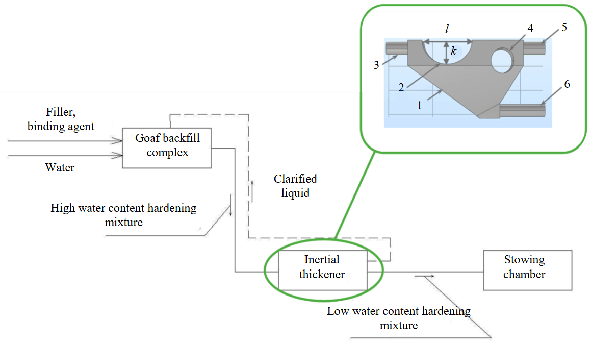
Fig.1. Technological scheme of hydraulic transport of stowage mixtures with thickening at the final stage of work:
1 – working chamber; 2 – main deflecting hydrodynamic profile; 3 – inlet branch pipe; 4 – cylindrical hydrodynamic profile; 5 – outlet branch pipe of clarified water; 6 – outlet branch pipe of thickened mixture; l – longitudinal length of profile; k – transverse length of profile
The calculation is based on the Euler – Lagrange method. The discrete phase model according to this method is constructed by solving the time-averaged Navier – Stokes equations for the liquid phase, considered as a constant medium (H.S.Fogler, 1992). The dispersed phase is described by tracing the trajectory of a given number of particles through the calculated flow fields [42-44]. The movement of the hydraulic mixture is specified by the modules: Turbulent flow k-w for the general movement of the hydraulic mixture and Particle Tracing for Fluid Flow for modeling the movement of the discrete phase in the flow. To determine the trajectory of solid particles during the movement of the hydraulic mixture in the turbulent regime, a surface grid consisting of 115.5 thousand elements is specified (Table 1).
Table 1
Mathematical model of the thickening process
|
Specified parameter |
Defining equations |
|
Change in the mass of the mixture |
where ρk – density of hydraulic mixture, kg/m3; t – time, s; ∇ – differential operator; Vhm – averaged mass flow rate of hydraulic mixture, m/s. |
|
Changes in particle volume fraction |
where αp – volume fraction of the dispersed phase in the flow of the hydraulic mixture in the range from 0 to 1; Vhp – average flow rate of hydraulic mixture in volume, m/s. |
|
Sliding speed |
where ρp, ρw – density of solid particles and carrier medium, kg/m3; μ – dynamic viscosity coefficient of hydraulic mixture, Pa·s; fd – distance traveled by a particle, m; α1 – volume fraction of the carrier medium in the flow of the hydraulic mixture in the range from 0 to 1; Dtp – coefficient of turbulent diffusion of solid particles of a hydraulic mixture. |
|
The coefficient of turbulent diffusion of solid particles of a hydraulic mixture |
where K – Lagrange multiplier; Cμ, Cβk – turbulence model constant k – ε; k – kinetic energy of turbulence, m2/s2; ε – turbulent dispersion velocity, m2/s3; γk – shear rate, time derivative of strain, s–1. |
|
Trajectory of movement of solid particles in a hydraulic mixture |
where mpv – mass of solid particles at a given speed, kg; Vp – average particle velocity; Ft – resultant of external forces, N. |
|
The amount of solid particles |
where τi – viscous stress tensor; τL – Lagrange response time; Vw – average speed of the carrier medium, m/s; Ie – unit tensor. |
|
The drag force per unit mass of a particle |
where τp – particle sedimentation time, s; mp – particle mass, kg. |
|
Particle deposition time |
where dp – diameter of solid particles, m. |
|
Lifting force |
where rp – radius of solid particle, m; LV – lift coefficient. |

Fig.2. Content of solid component in the pipes of thickened mixture (1) and clarified water (2) for initial velocities of movement of hydraulic mixture
To conduct the study, a numerical experiment method was chosen, which allows the most accurate characterization of the distribution of particles in the cross-section and their instantaneous position in changing velocity fields of the turbulent flow [45, 46]. The developed multiphysical model of the thickening process allows, in addition to changing the rheological parameters of the hydraulic mixture during its movement in the equipment, to estimate the change in the velocity of the carrier medium and the dispersed phase in the working area of the thickener during interaction with the profile surface. This made it possible to take into account velocity pulsations and the occurrence of ascending flows in the working area based on the specified parameters of the kinetic energy of the flow. The study of the movement of solid particles in the flow using the Euler – Lagrange method was performed with a volume fraction of the dispersed phase of 10 %.
A compacted discrete phase model was used for the solution, which overcomes the limitation on the acceptable volume fraction of solids by extending the Lagrange conservation equations, whereby the particles can achieve close packing. The governing equations were transformed into algebraic expressions. All working surfaces are subject to the boundary conditions of “non-slip walls”. The turbulent flow was calculated taking into account the force of gravity, while the particle trajectory was calculated taking into account the drag force and the force of gravity [33]. The verification of the recommended velocity is based on the assessment of the amount of solids in the outlet pipe of clarified water and thickened mixture using the method of cross-section mapping.
Discussion of results
The results of the study conducted to assess the distribution of the number of particles in the sections of the outlet pipes at different speeds of the primary mixture showed that at a flow rate of 2.0 m/s, the concentration of the dispersed phase in the section of the outlet pipe reaches 45 %. In the section of the outlet branch pipe for the clarified flow, the amount of solid particles was recorded at a level of 15 % of the initial one. Further studies showed that an increase in the velocity of the initial mixture entering the working zone contributes to a decrease in the number of dispersed phase particles in the branch pipe of the thickened mixture and an insignificant increase in their content in the branch pipe of the clarified mixture (Fig.2).
The identified recommended feed rate of the initial hydraulic mixture into the thickener working chamber is within 2.0 m/s lower than the maximum permissible flow rate of the hydraulic mixture adopted at the plant – 2.65-2.76 m/s (depending on the productivity of the surface stowing complex). An increase in the feed rate of the initial hydraulic mixture slightly reduces the content of the dispersed phase in the thickened flow – no more than 8 %, while the content of solid particles in the clarified liquid flow remains virtually unchanged. The limiting value of the feed rate of the hydraulic mixture into the inertial thickener, upon reaching which its use is not effective, is 0.9 m/s. In this case, a high carryover of the dispersed phase by the ascending flow of clarified liquid is observed and the risk of bottom sediment formation is high.
To confirm the obtained results, studies were conducted on the distribution of flow density and the formed flow velocity fields in the working chamber of the inertial thickener.
The distribution of flow velocities during interaction with hydrodynamic profiles at a hydraulic inlet velocity is shown in Fig.3, a, the distribution of vectors of the flow velocity fields of the hydraulic mixture, performed in Ansys Fluent, in Fig.3, b.
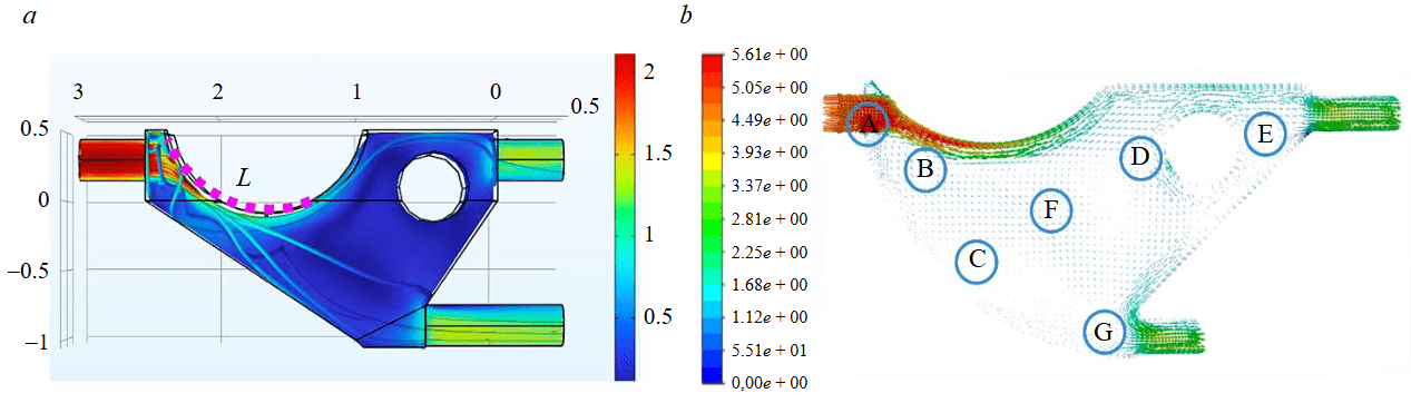
Fig.3. Distribution of the fields of parameters of the dynamic thickening process in the working zone of the thickener: a – solid particle velocities; b – flow velocity vectors; L – interaction section length
The picture of particle velocity distribution in the calculation area complements the idea of the thickener operating principle. The conducted study of the distribution of the velocity fields and the flow density of the hydraulic mixture in the working chamber of the inertial thickener allowed us to reveal that there are several zones in the chamber in which processes occur that determine the efficiency of sedimentation. Zone A is the area of primary interaction of the mixture with the surface of the main deflecting hydrodynamic profile. In the area limited by zone B, the attack area of the flowing profile is formed in the flow. This contributes to the mixture significantly deviating from the initial trajectory and significantly losing speed – more than twice. Fig.3, b shows the directions of movement of the flow sections and the division of the flow into the sediment-forming zone C and the ascending flow – zone F, in which the velocity decreases to 0.25 of the initial one. The dispersed phase, carried away by the ascending flow, collides with a cylindrical deflecting profile, which, cutting it, starts the process of secondary sedimentation. The particles enveloping its surface, descending along the inclined wall of the working chamber, form the final volume of the thickened flow – zone G, directed to the branch pipe for the thickened mixture for filling operations. Zone E designates the section for the removal of the dispersed phase particles remaining in suspension into the branch pipe for the clarified flow.
Inertial sedimentation is realized in the case when the kinetic energy of the particle is so great that the particle cannot follow the curved lines of flow and, colliding with an obstacle, settles in the allocated volume [47-49]. The inertial principle of thickening in the considered design is realized due to the force interaction of the dispersed phase with the deflecting hydrodynamic profiles. It is advi-sable to determine the ratios of its main design parameters. In parametric synthesis of equipment, this will ensure that the specified level of solid component concentration in the outlet pipe of the thickened mixture is achieved.
To substantiate the geometric parameters of the deflecting hydrodynamic profile, samples of the working chambers of the inertial thickener with different ratios of its longitudinal and transverse axes were studied. The dimensions of the inertial thickener may vary depending on the required flow concentration. To assess the impact of this on the efficiency of operation, a study was performed on the distribution of the dispersed phase in the working chamber and in the sections of the discharge pipes. Sets of rational combinations of parameters that ensure the formation of a thickened flow with the maximum possible content of the dispersed phase are presented in Table 2.
The obtained results made it possible to form a series of nomograms for the distribution of the dispersed phase in the flow to determine the rational ratio of the corresponding parameters (Fig.4).
Table 2
Distribution of the dispersed phase of the flow in the flow
|
b, mm |
Solids content, % |
||||
|
a, mm |
|||||
|
1,000 |
1,150 |
1,250 |
1,350 |
1,450 |
|
|
400 |
52/32/16* |
64/23/13 |
58/23/19 |
41/34/25 |
43/30/27 |
|
500 |
69/16/15 |
59/19/22 |
66/11/23 |
50/19/31 |
51/12/37 |
|
600 |
58/13/29 |
59/9/32 |
54/11/35 |
47/13/40 |
36/12/52 |
|
700 |
57/13/30 |
54/11/35 |
50/12/38 |
43/13/44 |
37/11/54 |
* Thickened mixture/clarified stream/sediment.
The ratio of the lengths of the longitudinal and transverse axes of the deflecting profile N = a/b is an invariant of geometric similarity. This value, independent of the dimensions of the natural and model object, can correspond to a change in the concentration of the formed flow in a wide range of values.
The ratio of characteristic parameters of the deflecting hydrodynamic profile sets the shape of the deflecting profile and determines the area of interaction of the profile with the flow entering the working chamber. Depending on the angle of attack of the flow, the inertial reflection of particles also occurs at different angles, determines the change in the direction of the flow and is accompanied by a change in the velocity of the dispersed phase (Fig.5).
The similarity criterion for inertial sedimentation is the Stokes criterion [32]:
where V – flow velocity in the selected coordinate of the unsteady flow, m/s; r – radius of curvature of the streamlined surface, m; ρ – density of dispersed phase, kg/m3; μ – dynamic viscosity of the carrier medium, kg/m·s; L – characteristic linear size of the interaction area of a streamlined body, m (see Fig.3, a).
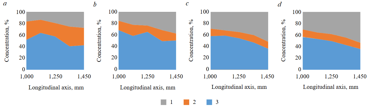
Fig.4. Nomograms of the distribution of the dispersed phase in the inertial thickener for different values of the transverse axis of the deflection profile:
a – 400 mm; b – 500 mm; c – 600 mm; d – 700 mm
1 – sediment; 2 – clarified liquid; 3 – thickened stream
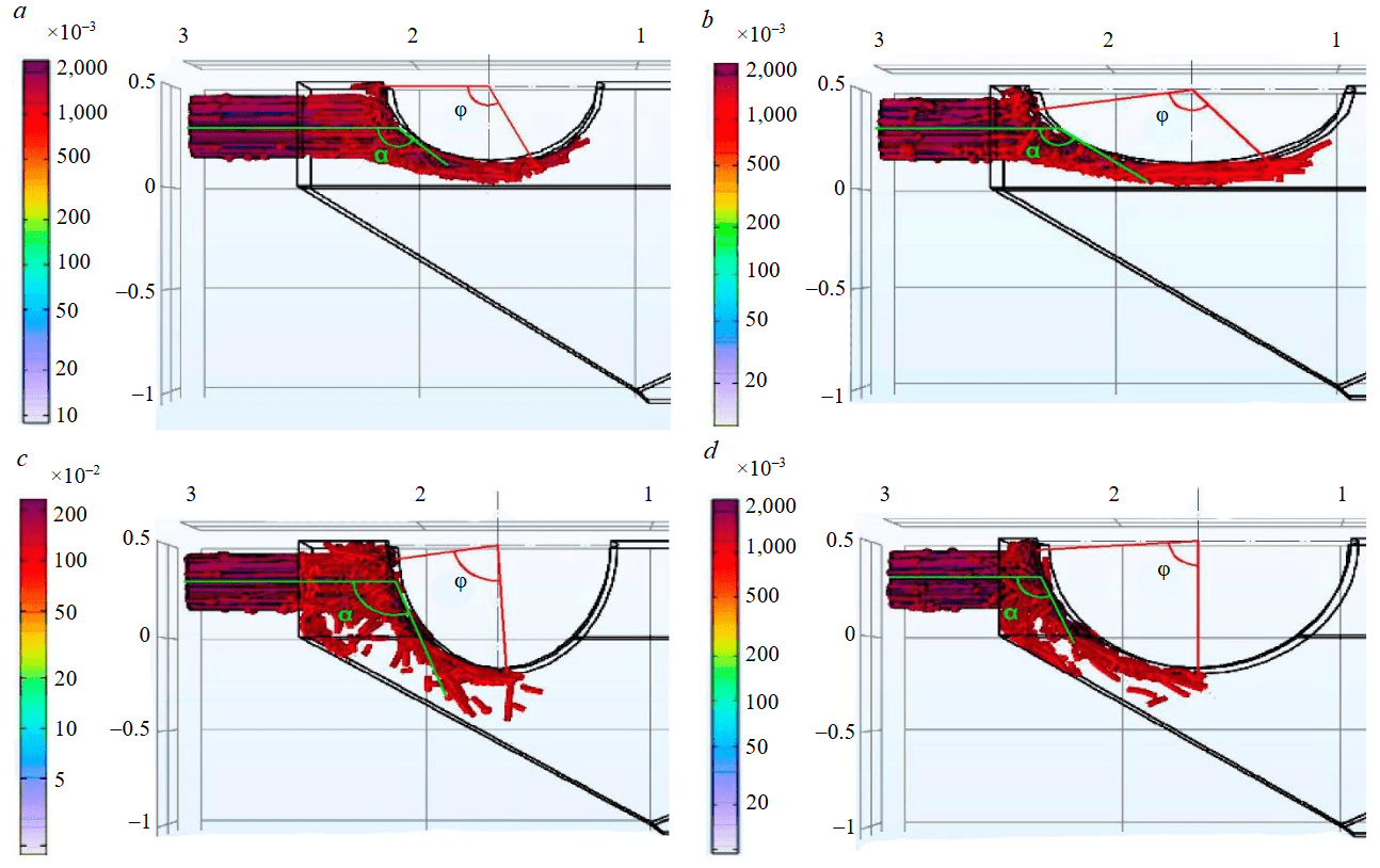
Fig.5. Formation of flow interaction areas with different ratios of transverse and longitudinal axes of the deflection profile: a – 400/1000 mm; b – 400/1450 mm; c – 700/1000 mm; d – 400/1450 mm
The calculation of the characteristic linear size of the interaction area of the streamlined body and the flow is performed according to the second Ramanujan formula for determining the length of the perimeter of an ellipse [50]:
where a – value of longitudinal dimension of profile, m; b – value of transverse dimension of profile, m; Z=(a-b)/(a+b) – ratio of major and minor semi-axes.
As a result of the study of the distribution of the contact density of the flow, patterns of the distribution of the corresponding areas of interaction were obtained, forming the zones of flow around the surface of the hydrodynamic profile by the suspension-carrying flow (Fig.5). The formation of the trajectory of the flow movement is determined by the angle of attack of the flow α and the angle of flow around the profile φ, the value of which depends on the ratio of the lengths of the longitudinal and transverse dimensions of the profile.
The influence of the profile geometry on the flow parameters and subsequent inertial settling, determined by the characteristic length of the contact zone, can be estimated by the corresponding angle of attack of the flow α. The results of the assessment of their change depending on the profile parameters are presented in Fig.6. As follows from Fig.5, the length of the section of interaction of the flow with the profile is characterized by the flow angle φ.The dynamics of the increase in angle φ corresponds to the change in the characteristic length of the interaction section L.An increase in the longitudinal profile dimension has little effect on the change in the angle φ, accompanied by an increase in L due to an increase in the overall length of the profile. An increase in the transverse profile dimension leads to a relative decrease in this angle due to a change in the overall shape. At the same time, the tendency to increase the length of the interaction section L is preserved. The angles of attack and flow around the flow are significantly reduced with an increase in the transverse profile dimension.
Analysis of the parameters of the distribution of suspension-carrying flows and the formed trajectories of particle motion showed that an increase in the ratio of the lengths of the longitudinal and transverse dimensions of the deflecting profile is accompanied by an increase in the characteristic length of the section of interaction with the flow L (Fig.7, a). Results of a comprehensive analysis, including an assessment of the effect of an independent change in the characteristic overall parameters of the deflecting profile on the concentration of the formed condensed flow at the outlet of the working chamber. In addition, the corresponding lengths of the formed flow zones were determined. A nomogram has been compiled, displaying the selected area of flow concentration change and allowing to correlate it with the corresponding dimensions of the deflecting profile (Fig.7, b). The dotted lines mark the corresponding process of formation of areas of interaction with the flow, characterizing the flow zones, occurring within the framework of the selected profile geometry.
According to the obtained nomogram, an increase in the longitudinal dimension of the profile is accompanied by a decrease in the concentration of the thickened flow of the hydraulic mixture. An increase in the transverse dimension of the profile within the specified limits does not lead to a decrease in the concentration of the formed flow. In some cases, this allows for the conditions for achieving the content of the dispersed phase within 70 % by weight. An increase in the length of the flow zone leads to a decrease in concentration due to a decrease in the inertial effect on the flow, determined by the angle of attack of the flow, accompanied by a change in the trajectory of dispersed particles.
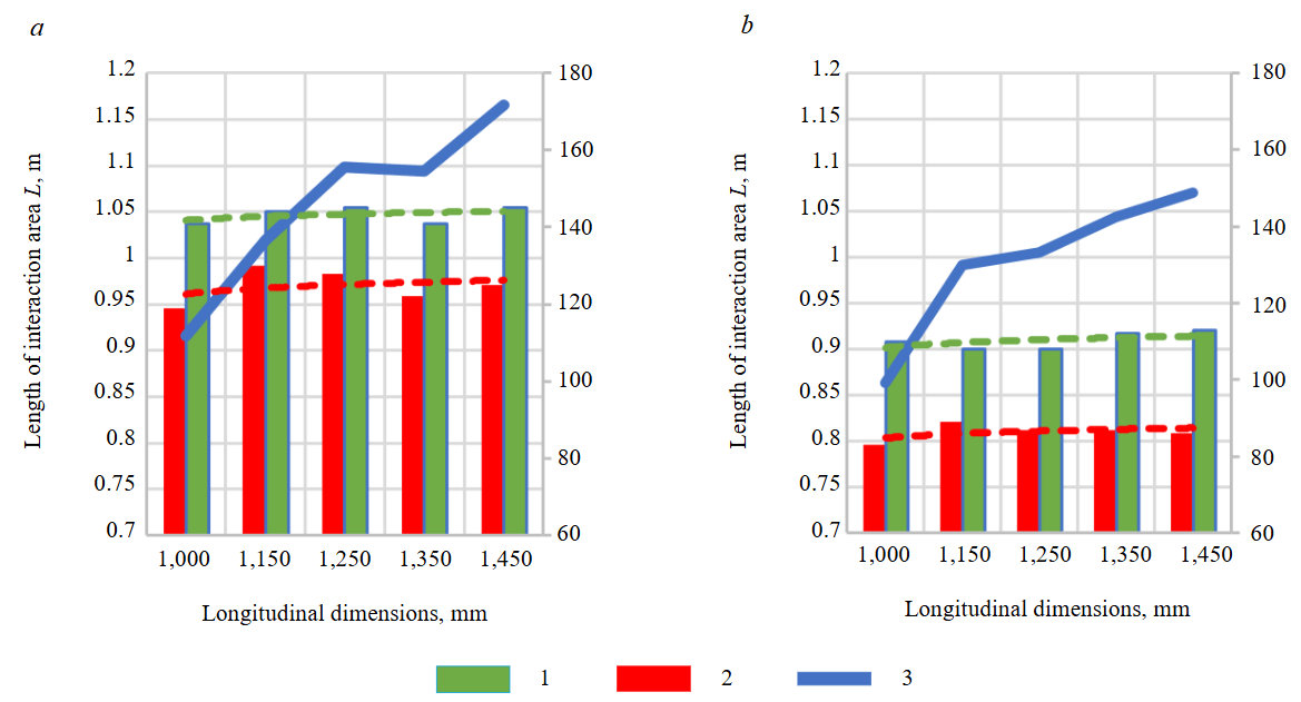
Fig.6. Change in the characteristic length of the interaction section L from the characteristic angles of interaction with the deflecting profile: a – longitudinal dimension 1000 mm, transverse dimension 400 mm; b – longitudinal dimension 1,450 mm, cross dimension 700 mm
1 – flow angle, deg; 2 – angle of attack, deg; 3 – L, m
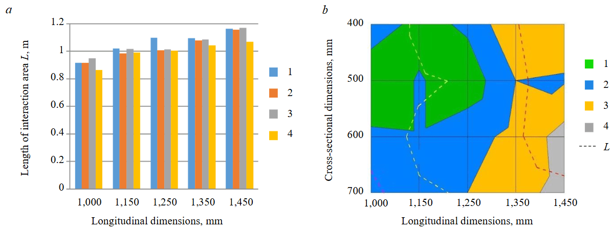
Fig.7. Dynamics of change of characteristic parameters of thickening depending on the ratios of characteristic overall parameters of the deflection profile: a – change of characteristic length of the interaction section (1 – transverse dimension 400 mm; 2 – 500 mm; 3 – 600 mm; 4 – 700 mm); b – nomogram of change of concentration of thickened flow (1 – 60-70 %; 2 – 50-60 %; 3 – 40-50 %; 4 – 30-40 %)
Conclusion
As a result of the research carried out, a number of conclusions were made that have scientific and practical significance:
- The supply of backfill mixtures over long distances is significantly limited by the reduction in specific hydrodynamic pressure, determined by the ratio of the vertical and horizontal components of the backfill pipeline, as well as the complex resistance of the channel, which forces the use of flowing mixtures with a low solid phase content in the technological process.
- Hydraulic mixtures for backfilling work containing inorganic binders are dilatant substances which, due to the internal interaction of the particles of the dispersed phase, are structured in the volume. This corresponds to the observed power dependence of the change in shear stress on the velocity gradient during flow movement, known as the Ostwald – de Waale rheological law, and corresponding to the generalized Herschel – Bulkley model.
- The determining factors in the use of thickening equipment are the productivity of the stowage pipeline, the degree of thickening and the granulometric composition of the mixture. The type of thickener must correspond to the features of the stowage complex. The use of the inertial principle of thickening is due to the need to implement a continuous technology for feeding the stowage material, as well as the compactness of the equipment dimensions.
- Thickening of the hydraulic mixture used during stowage operations is recommended to be carried out at the final stage of transportation of the stowage material. This allows the use of the initial hydraulic mixture with a low content of the dispersed phase in the technological process and to
implement reverse water drainage. - A mathematical model for determining the trajectories of the dispersed phase using the Euler – Lagrange method, constructed by solving the time-averaged Navier – Stokes equations for the liquid phase, considered as a constant medium. This made it possible to analyze the efficiency of the process of particle deposition and the formation of a condensed flow, as well as to evaluate the influence of the parameters of the initial hydraulic mixture. The trajectories of a limited number of particles through the calculated flow fields are considered as a discrete dynamic system, and Poincare sections are used for their analysis.
- The content of the dispersed phase in the thickened flow depends on the trajectories of the particles, determined by the value of the characteristic length of the interaction section L, varied by changing the ratio of the longitudinal and transverse dimensions of the deflecting hydrodynamic profile of the working chamber of the inertial thickener, the angles of attack and flow around the flow.
- An increase in the transverse dimension of the deflecting profile is accompanied by a decrease in the angle of attack of the flow, significantly changing the trajectory of the flow of dispersed particles, and contributes to the effective implementation of the inertial thickening mechanism.
References
- Zubov V.P., Anisimov K.A. Resource-saving underground mining technology for diamond-bearing kimberlite ore under protective cushion below open pit mine bottom. Gornyi zhurnal. 2023. N 4, p. 26-37 (in Russian). DOI: 10.17580/gzh.2023.04.05
- Kaplunov D.R., Ryl'nikova M.V., Radchenko D.N. Prospects for the development of technology for backfilling mined-out space during underground mining of ore deposits. Mining Informational and Analytical Bulletin. 2011. N 12, p. 5-10.
- Belikov A.A., Belyakov N.A. Method of predicting the stress-strain state of interchamber pillars lined with a compliant rope fastener. Mining Informational and Analytical Bulletin. 2023. N 4, p. 20-34. DOI: 10.25018/0236_1493_2023_4_0_20
- Sokolov I.V., Antipin Yu.G., Nikitin I.V. Basic principles and assessment criteria of technological strategy for underground mining in transition zones. Mining Informational and Analytical Bulletin. 2017. N 9, p. 151-160 (in Russian). DOI: 10.25018/0236-1493-2017-9-0-151-160
- Atroshchenko V.A., Alexandrov V.I. Increasing the Efficiency of the Transport Pipelines of the Stowing Complex with the Application of a Polyurethane Coating. Mining Informational and Analytical Bulletin. 2022. Vol. 10-1, p. 25-38. DOI: 10.25018/0236_1493_2022_101_0_25
- Mengyi Liu, Haijun Lu, Qingkai Deng et al. Shear strength, water permeability and microstructure of modified municipal sludge based on industrial solid waste containing calcium used as landfill cover materials. Waste Management. 2022. Vol. 145, p. 20-28. DOI: 10.1016/j.wasman.2022.04.031
- Raffaldi M.J., Seymour J.B., Richardson J. et al. Cemented Paste Backfill Geomechanics at a Narrow-Vein Underhand Cut-and-Fill Mine. Rock Mechanics and Rock Engineering. 2019. Vol. 52. Iss. 12, p. 4925-4940. DOI: 10.1007/s00603-019-01850-4
- Montyanova A.N., Trofimov A.V., Rumyantsev A.E. et al. Experience and efficiency of application of plasticized backfilling concrete. Vestnik of Nosov Magnitogorsk State Technical University. 2019. Vol. 17. N 1, p. 18-25 (in Russian). DOI: 10.18503/1995-2732-2019-17-1-18-25
- Kovalski E.R., Gromtsev K.V., Petrov D.N. Modeling deformation of rib pillars during backfill. Mining Informational and Analytical Bulletin. 2020. N 9, p. 87-101 (in Russian). DOI: 10.25018/0236-1493-2020-8-0-87-101
- Shuai Li, Zeming Zhao, Haoxuan Yu, Xinmin Wang. The Recent Progress China Has Made in the Backfill Mining Method, Part II: The Composition and Typical Examples of Backfill Systems. Minerals. Vol. 11. Iss. 12. N 1362. DOI: 10.3390/min11121362
- Kovalskii E.R., Gromtsev K.V. Development of the technology of stowing the developed space during mining. Journal of Mining Institute. 2022. Vol. 254, p. 202-209. DOI: 10.31897/PMI.2022.36
- Anisimov K.A., Nikiforov A.V. Modern technologies of the development of diamondiferous deposits. Bulletin of the Tomsk Polytechnic University. Geo Аssets Engineering. 2023. Vol. 334. N 1, р. 196-208 (in Russian). DOI: 10.18799/24131830/2023/1/3837
- Kuskildin R.B., Vatlina A.M. Method of accelerated industrial testing of hydroabrasive wear of polymer coatings of steel pipes. Journal of Physics: Conference Series. 2021. Vol. 1728. N 012029. DOI: 10.1088/1742-6596/1728/1/012029
- Golik V.I., Razorenov Yu.I., Dzeranov B.V. Combined delivery of hardening mixtures to remote deposit sites. Bulletin of the Kuzbass State Technical University. 2017. N 4, p. 14-19 (in Russian). DOI: 10.26730/1999-4125-2017-4-14-19
- Lyashenko V.I., Golik V.I., Dmitrаk Yu.V., Franchuk V.P. Rationale for the Parameters of the Vibration Gravity Transportation of Solidifying Filling Mixtures to Mines. Vestnik of Nosov Magnitogorsk State Technical University. 2021. Vol. 19. N 1, p. 4-16 (in Russian). DOI: 10.18503/1995-2732-2021-19-1-4-16
- Protosenya A.G., Kutepov Yu.Yu. Stability estimation of hydraulic fills in undermined areas. Mining Informational and Analytical Bulletin. 2019. N 3, p. 97-112 (in Russian). DOI: 10.25018/0236-1493-2019-03-0-97-112
- Svakhina Y.A., Titova M.E., Pyagay I.N. Products of Apatite-Nepheline Ore Processing in the Synthesis of Low-Modulus Zeolites. Indonesian Journal of Science & Technology. 2023. Vol. 8. N 1, p. 49-64. DOI: 10.17509/ijost.v8i1.51979
- Volkov E.P., Vokhmin S.A., Anushenkov A.N., Golovanov A.I. Development of Formulations and the Mechanism of Activation of Mixtures for Underground Mining with use of Mill Tailings. Journal of Siberian Federal University. Engineering & Technologies. 2014. Vol. 7. N 3, p. 295-303 (in Russian).
- Stovmanenko A.Yu., Anushenkov A.N. Increase of system effectiveness of pipeline transport of cast stowage mixes at their mechanical activation, in the conditions of underground mining of mineral deposits. News of the Ural State Mining University. 2016. Iss. 1 (41), p. 94-102 (in Russian).
- Golik V.I., Komashchenko V.I., Shkuratskyi D.N. Optimization of composition of hardening mixes on geomechanical conditions by mining ore fields. News of the Tula state university. Sciences of Earth. 2016. N 3, p. 164-176 (in Russian).
- Hengfeng Liu, Jixiong Zhang, Baiyi Li et al. Environmental behavior of construction and demolition waste as recycled aggregates for backfilling in mines: Leaching toxicity and surface subsidence studies. Journal of Hazardous Materials. 2020. Vol. 389. N 121870. DOI: 10.1016/j.jhazmat.2019.121870
- Jiahao Qin, Jian Zheng, Li Li. An analytical solution to estimate the settlement of tailings or backfill slurry by considering the sedimentation and consolidation. International Journal of Mining Science and Technology. 2021. Vol. 31. Iss. 3, p. 463-471. DOI: 10.1016/j.ijmst.2021.02.004
- Smirnov O.Iu. Investigating the conditions of applying the filling method of field development in various mining and geological conditions. News of the Higher Institutions. Mining Journal. 2019. N 5, p. 14-20 (in Russian). DOI: 10.21440/0536-1028-2019-5-14-20
- Golik V.I., Tsidaev T.S., Tsidaev B.S. Improving the efficiency of ore mining by combining traditional and innovative technologies. Mining Informational and Analytical Bulletin. 2012. N 4, p. 11-18.
- Pirogov G.G., Voronov E.T. Composite granular backfill in stoping by stripes. Mining Informational and Analytical Bulletin. 2021. N 3-2, p. 125-132 (in Russian). DOI: 10.25018/0236_1493_2021_32_0_125
- Matveenko V.N., Kirsanov E.A. Structural rationale of a non-Newtonian flow. Moscow University Chemistry Bulletin. 2017. Vol. 72. N 2, p. 69-91. DOI: 10.3103/S0027131417020031
- Matvienko O.V., Bazuev V.P., Cherkasov I.S., Aseeva A.E. Hydraulic properties of sand slurry flow in a pipe. Journal of Construction and Architecture. 2020. Vol. 22. N 2, p. 129-144 (in Russian). DOI: 10.31675/1607-1859-2020-22-2-129-144
- Daihui Lu, Christov I.C. Physics-informed neural networks for understanding shear migration of particles in viscous flow. International Journal of Multiphase Flow. 2023. Vol. 165. N 104476. DOI: 10.1016/j.ijmultiphaseflow.2023.104476
- Shammazov I., Karyakina E. The LNG Flow Simulation in Stationary Conditions through a Pipeline with Various Types of Insulating Coating. Fluids. 2023. Vol. 8. Iss. 2. N 68. DOI: 10.3390/fluids8020068
- Matvienko O.V., Litvinova A.E. Steady flow of high-paraffin bituminous binder in cylindrical tube in terms of Herschel – Bulkley fluid. Journal of Construction and Architecture. 2021. Vol. 23. N 4, p. 79-99 (in Russian). DOI: 10.31675/1607-1859-2021-23-4-79-99
- Ilinov M.D., Petrov D.N., Kolontaevsky E.V., Straupnik I.A. Usability of acrylates in damp proofing in deep-level salt mining. Gornyi zhurnal. 2023. N 8, p. 77-87 (in Russian). DOI: 10.17580/gzh.2023.08.10
- Seiphoori A., Gunn A., Kosgodagan Acharige S. et al. Tuning Sedimentation Through Surface Charge and Particle Shape. Geophysical Research Letters. 2021. Vol. 48. Iss. 7. N e2020GL091251. DOI: 10.1029/2020GL091251
- Vasilyeva M.A., Volchikhina A.A., Morozov M.D. Re-backfill technology and equipment. Mining Informational and Analytical Bulletin. 2021. N 6, p. 133-144 (in Russian). DOI: 10.25018/0236_1493_2021_6_0_133
- Lyashenko V.I., Khomenko O.E., Chekushina T.V. et al. Technologies and equipment for mining and metallurgy waste management. Mining Informational and Analytical Bulletin. 2021. N 12, p. 132-148 (in Russian). DOI: 10.25018/0236_1493_2021_12_0_132
- Aleksandrova T., Nikolaeva N., Afanasova A. et al. Justification for Criteria for Evaluating Activation and Destruction Processes of Complex Ores. Minerals. 2023. Vol. 13. Iss. 5. N 684. DOI: 10.3390/min13050684
- Kibirev V.I., Bauman A.V., Nikitin A.E. On the creation of modern Russian thickeners. Gornaya promyshlennost. 2017. N 5 (135), p. 32-34.
- Bauman A.V. Upon modernization of domestically produced radial thickeners. Obogashchenie rud. 2013. N 1, p. 44-49 (in Russian).
- El Moutea O., El Amri H., El Akkad A. Finite Element Method for the Stokes–Darcy Problem with a New Boundary Condition. Numerical Analysis and Applications. 2020. Vol. 13. N 2, p. 136-151. DOI: 10.1134/S1995423920020056
- Scutaru M.L., Guendaoui S., Koubaiti O. et al. Flow of Newtonian Incompressible Fluids in Square Media: Isogeometric vs. Standard Finite Element Method. Mathematics. 2023. Vol. 11. Iss. 17. N 3702. DOI: 10.3390/math11173702
- Togun H., Homod R., Sadeghinezhad E., Kazi S.N. Navier-Stokes Equations and High-Resolutions: Advancements in Accurate Incompressible Flow Simulations. Knowledge-Based Engineering and Sciences. 2023. Vol. 4. N 2, p. 51-59. DOI: 10.51526/kbes.2023.4.2.51-59
- Vasilyeva M.A., Vöth S. Multiphysical Model of Heterogeneous Flow Moving Along a Channel of Variable Cross-section. Journal of Mining Institute. 2017. Vol. 227, p. 558-562. DOI: 10.25515/PMI.2017.5.558
- Adamczyk W.P., Klimanek A., Białecki R. et al. Comparison of the standard Euler – Euler and hybrid Euler – Lagrange approaches for modeling particle transport in a pilot-scale circulating fluidized bed. Particuology. 2014. Vol. 15, p. 129-137. DOI: 10.1016/J.PARTIC.2013.06.008
- Esgandari B., Rauchenzauner S., Goniva C. et al. A comprehensive comparison of Two-Fluid Model, Discrete Element Method and experiments for the simulation of single- and multiple-spout fluidized beds. Chemical Engineering Science. 2023. Vol. 267. N 118357. DOI: 10.1016/j.ces.2022.118357
- Yongchao Li, Defu Che, Yinhe Liu. CFD simulation of hydrodynamic characteristics in a multiple-spouted bed. Chemical Engineering Science. 2012. Vol. 80, p. 365-379. DOI: 10.1016/J.CES.2012.06.003
- Careaga J., Gatica G.N. Coupled mixed finite element and finite volume methods for a solid velocity-based model of multidimensional sedimentation. ESAIM: Mathematical Modelling and Numerical Analysis. 2023. Vol. 57. N 4, p. 2529-2556. DOI: 10.1051/m2an/2023057
- Fukui T., Kawaguchi M., Morinishi K. Numerical study on the inertial effects of particles on the rheology of a suspension. Advances in Mechanical Engineering. 2019. Vol. 11. Iss. 4, p. 10. DOI: 10.1177/1687814019847000
- Tak Shing Lo, Koplik J. Channeling and stress during fluid and suspension flow in self-affine fractures. Physical Review E. 2014. Vol. 89. Iss. 2. N 023010. DOI: 10.1103/PhysRevE.89.023010
- Voulgaropoulos V., Jamshidi R., Mazzei L., Angeli P. Experimental and numerical studies on the flow characteristics and separation properties of dispersed liquid-liquid flows. Physics of Fluids. 2019. Vol. 31. Iss. 7. N 073304. DOI: 10.1063/1.5092720
- Wenwei Liu, Chuan-Yu Wu. Analysis of inertial migration of neutrally buoyant particle suspensions in a planar Poiseuille flow with a coupled lattice Boltzmann method-discrete element method. Physics of Fluids. 2019. Vol. 31. Iss. 6. N 063301. DOI: 10.1063/1.5095758
- Ce Xu. Some Evaluation of Infinite Series Involving Trigonometric and Hyperbolic Functions. Results in Mathematics. 2018. Vol. 73. Iss. 4. N 128. DOI: 10.1007/s00025-018-0891-9