
Comprehensive assessment of deformation of rigid reinforcing system during convergence of mine shaft lining in unstable rocks
- 1 — Ph.D. Head of Laboratory АО VNII Galurgii ▪ Orcid
- 2 — Ph.D., Dr.Sci. Chief Researcher AО VNII Galurgii ▪ Orcid
- 3 — Leading Engineer АО VNII Galurgii ▪ Orcid
Abstract
Operation of vertical mine shafts in complex mining and geological conditions is associated with a number of features. One of them is a radial displacement of the concrete shaft lining, caused by the influence of mining pressure on the stress-strain state of the mine workings. A rigid reinforcing system with shaft buntons fixed in the concrete lining thus experiences elastoplastic deformations, their value increases with time. It results in deviation of conductors from design parameters, weakening of bolt connections, worsening of dynamic properties of geotechnical system “vehicle – reinforcing”, increase of wear rate of reinforcing system elements, increase of risks for creating an emergency situation. The article offers a comprehensive assessment of displacements of characteristic points of the bunton system based on approximate engineering relations, numerical modeling of the deformation process of the bunton system and laser measurements of the convergence of the inner surface of the concrete shaft lining. The method was tested on the example of the reinforcing system of the skip-cage shaft of the potash mine. Displacement of the characteristic points of the reinforcing system is determined by the value of radial displacements of the surface of the concrete shaft lining. Evaluation of the radial displacements was made using monitoring measurements and profiling data. The results obtained make it possible to justify the need and timing of repair works. It is shown that the deterioration of the reinforcing system at different levels occurs at different rates, defined, among other things, by mechanical properties of the rock mass layers located at a given depth.
None
Introduction
Vertical mine shafts are considered to be of the first class of importance, as their failure to operate properly can lead to shutdown of the entire company (SP 91.13330.2012). The main factor of reliable and accident-free operation of a mine shaft is the serviceability of its reinforcing system, consisting of a system of structures ensuring the movement of the vehicles under specified modes of operation of the lifting unit during the entire operating life of the shaft [1]. Calculation of rigid reinforcing is performed according to the conditions of dynamic stability of the movement of the vehicles in the conductors and is carried out at the stage of mine shaft design. Besides, the elements included in the reinforcing are calculated for compliance with the stiffness and strength characteristics [1-3]. The other loads are considered insignificant, so they are neglected in the calculation or some reserve coefficients are taken into account when determining the loads from the vehicles [4]. Simplifying the calculation scheme may lead to inaccurate determination of the parameters of rigid reinforcing of potash mine shafts, therefore, it is necessary to take into account the complex time-varying interaction of the geotechnical system “rigid reinforcing – shaft lining” [4].
It is known from field observations [5], that during the operation of potash mine shafts, corrosion and mechanical wear of buntons and guide conductors inevitably occurs. Wear of the reinforcing elements results in changes in their geometric parameters – reduction of conductor and bunton wall thickness and reduction of stiffness of the entire reinforcing system. If the shaft is in complex mining and geological conditions (unstable rock mass, loading from additional excavations, etc.), then deformations of some sections of the lining and, consequently, of the reinforcing occur. Deformations in a concrete monolith can reach such a magnitude that at a certain point a situation arises, at which it is impossible for the vehicle to pass freely in the conductor track. It results in deterioration of dynamic properties of the system “vehicle – reinforcing” and reduction of operation parameters [5, 6]. To eliminate the failure, the deformed section of the bunton is replaced with a straight section of the bunton, whereby it is previously released by pressing the bunton end embedment out of the concrete lining [6]. Each bunton embedment point is opened to the size necessary to bring the conductor track to the base, design position. If necessary, not only the concrete lining is removed, but also the salt rock is stripped to sufficient length and width. A detailed description of the working conditions of the rigid shaft reinforcing with a list of the main load types and their effect on the reinforcing is presented in the papers [7-9].
Statement of problem
Studies by various authors have established that during the operation of a mine shaft in complex mining and geological conditions, deformation of the concrete lining is observed as a result of change of the rock mass containing the shaft [10-12]. Deformation of the concrete lining is transmitted to the rigid reinforcing, resulting in the disruption and design change of the buntons and conductors [13-15]. Various aspects of the effect of undermined areas on shaft geometry and performance are discussed in the papers [16, 17].
The following problems accumulate and occur during continuous operation of the mine shaft lining and reinforcing system [18-20]:
- changes in the track geometry of the guide conductors which can lead to out of track or jamming of the vehicles. It threatens to cause an emergency situation with severe consequences;
- due to intensive abrasion of the conductors and buntons, accumulation of fatigue stresses and corrosion wear, the service life of the reinforcing elements decreases;
- cost of operating the shafts, related to time-consuming regular inspections and labor-intensive repairs of the reinforcing fixing points, increases.
To solve these problems, it is necessary to perform a comprehensive assessment of the technical state of all the elements of the rigid reinforcing as a single frame structure, taking into account the convergence of the concrete lining.
Thus, the task of the research is to study the features of joint deformation of the geotechnical system “rigid reinforcing – shaft lining” followed by the assessment of critical deformations and their influence on the choice of structural and technological solutions for reinforcing vertical shafts.
Methods
To settle out the given problem both the engineering approach and numerical approach were used – finite element method (FEM) using ANSYS application program package. It is necessary to determine the relationships between the magnitude of the concrete lining convergence and the magnitude of deformation (displacements) of the rigid reinforcing by the example of the skip-cage mine shaft of the potash mine. In practice, instrumental methods of investigation and control of reinforcing systems and vehicles using modern measuring tools [21-23] and monitoring [24] are widely used. As calculation methods, primarily the engineering method is applied [25-27], based on approximate approaches of theoretical mechanics and resistance of materials [28, 29]. Approaches based on numerical solution of such problems by the finite element method are also developed [30-32]. Some of them consider box steel structures with corrosion taken into account [33-35]. Note that only individual elements of reinforcing systems have been considered by numerical modeling methods so far, although it seems to the authors that this method, combined with instrumental monitoring methods, has significant promise.
This paper offers a comprehensive approach to the study of joint deformation of the geotechnical system “rigid reinforcing – shaft lining”, including engineering and numerical methods, as well as instrumental measurements of the lining deformation. Approximate relations are presented and a 3D-numerical model has been developed to assess deformations of the rigid shaft reinforcing system with respect to the convergence of the concrete shaft lining. The stress-strain state and displacements of the reinforcing system were determined by the example of the skip-cage shaft of the potash mine. A predictive assessment of the reinforcing performance under the constant effect of the convergence factor of the concrete lining in salt rocks is presented.
Engineering problem statement
The main task for engineering evaluation of the reinforcing performance under the effect of the convergence factor of the inner diameter of the concrete lining is an analysis of the displacements of characteristic points for the complex bunton system over time. It is impossible to formulate equations for analytical determination of the displacements of the characteristic points for the complex bunton system with respect to all interfaces and fixing points. Here we shall take only approximate (engineering) estimates of the displacements within the framework of the following assumptions. All the fixing points of the reinforcing levels in the concrete lining are moved radially by the magnitude ΔR, determined by the lining convergence during salt rock creep under the effect of rock pressure and dependent on time.
Let us introduce the ОХY coordinate system with the coordinate origin located in the centre of the shaft (Fig.1). Here letters A, B, …, I, J mark the points of fixing the shaft buntons R1-R8 to the concrete lining, and letter B1 marks a new position of point B at radial convergence of the shaft lining. Based on the geometrical dimensions of the bunton system, for each fixing point we can determine the angle between radial direction (the segment connecting the shaft centre and the given point, the segment shown by the dotted line) and the axis OX. Figure 1 as an example shows an angle φB for the fixing point B. Through these angles, for each fixing point, we can find displacements of the corresponding point along the coordinate axes, e.g.
Based on the displacements of all the reinforcing fixing points, it is necessary to evaluate new positions of the junction points of longitudinal and transverse buntons (points M, N, Q, S, V, W). In general, it is a complex nonlinear problem that needs to take into account both the change of the angles in the points of fixing and junction of the buntons and their possible bending in the horizontal plane due to loss of stability. In case of bending, the central part of the bunton span receives additional displacement. Considering all these factors when obtaining engineering estimates requires additional assumptions.
Let us take the bunton R5 as an example. This bunton has junctions with the bunton R6 in the point M and the bunton R7 in the point N (Fig.1), with possible bending, resulting in maximum displacement along the X axis of the middle of the bunton at the connection point with the conductor P3.
The point М at the shaft lining convergence will turn to the point М1, and the fixing points B and C – to the points B1 and C1. We assume that the bunton segments maintain their lengths BM = B1M1 and CM = C1M1 (in this case, the BMC junction angle may change). Therefore, the coordinates of the new fixing points
Let us say that
It should be noted that the position of the point M1 will be also influenced by other displacements of the points D, E, as well as by the junction points of the buntons R5 and R7. In addition, large bunton spans between the fixing points and/or the junction points may bend in the horizontal plane.
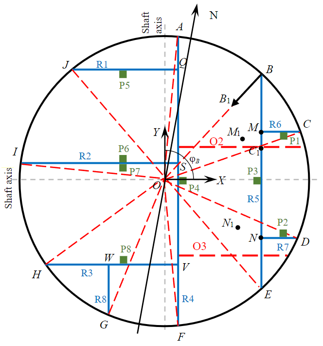
Fig.1. Scheme of buntons and conductors (by the example of the skip-cage shaft)
We shall estimate the bending deflection of the bunton R5 in the section М1N1, assuming that there is a loss of stability of the bunton at its compression in the direction along its axis. As we know, when the critical compression force is reached, the beam loses stability and takes a new (in the special case, flat) sinusoidal shape [36]. The number (or fraction thereof) of sinusoidal waves depends on the boundary conditions of the beam fixation. In our case, the compressive forces do not act strictly coaxially, since for the considered cases the buntons are embedded in the concrete lining, which deforms radially over time, creating two projections of bunton end displacements: along and across its axis.
Following the article [36], we assume that the bending curve of the clamped beam at loss of stability represents a half-wave of the sinusoid shown in Fig.2, where half of the bent curve of the beam is shown, the dotted line shows its initial position.
The initial length of the bunton is L. The bunton bends with a bending deflection С, which should be estimated after displacement of one end of the beam along its axis relative to the other (fixed) end by the value of Δ. The condition for determining the bending deflection C is the equality of the initial length of the bunton half L/2 and its length S in a bent state. As we know the length of the curve is defined by the integral [37]
where a – integration length; у′– derivative of x.
In our case y = 0.5Csin (πx/a); a = 0.5 (L – Δ). By entering a new variable m = – (0.5Cπ/a)2, we link together the relation (1) and the full normal Legendre elliptic integral of the 2nd type E2(m), having no expression in quadrature,
At small m (the bending deflection is signifi-cantly smaller than the bunton length), the function E2(m) decomposes as a rapidly descending power series
where О(m3) – a value (residue of the power series), which order does not exceed m3.
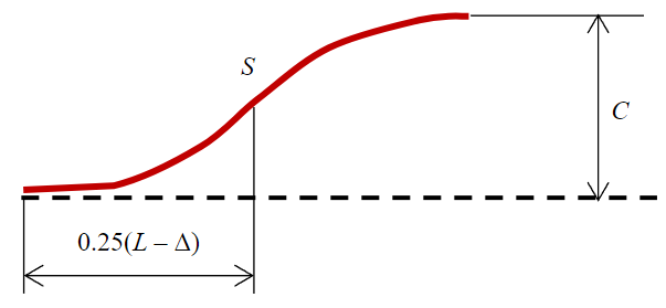
Fig.2. Bending scheme of the bunton beam
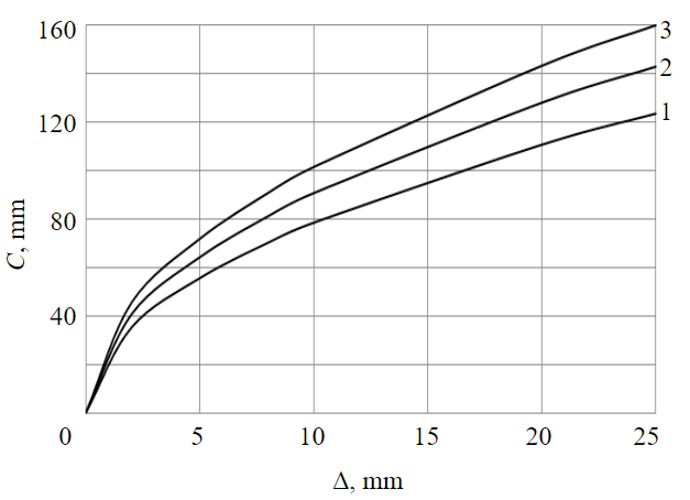
Fig.3. Dependence of the bending deflection on the magnitude Δfor different bunton lengths
1 – 1.5 m; 2 – 2.0 m; 3 – 2.5 m
In this case m ≤ 0.1, consequently, it is enough to use two members of the series in the decomposition (7) to obtain a reasonable engi-neering approximation.
Thus, in view of the requirement for the equality of the lengths of the bunton beam curves before and after deformation, the expressions for a, m and the decomposition (7), we obtain
Relationship (8) allows us to get an analytical expression for the bending deflection
Figure 3 shows a strong nonlinearity of the dependence on the magnitude of displacement of the bunton end along its axis Δ, especially at small values Δ: thus, at Δ = 5 mm, the bending deflection C = 55-72 mm in the presented range L. The obtained dependencies will be discussed when analyzing the bunton system by the example of the skip-cage shaft.
Estimation of displacements of the bunton characteristic points
From the perspective of accident-free operation of the reinforcing and the vehicles, first of all, it is important to assess the magnitude of displacements of the bunton points in the directions perpendicular to the bunton, in the places of conductor attachment, as they can cause the vehicle both to jam and to move out of the track of the guide conductors. The displacements of interest can be expressed through the corresponding displacements of the bunton fixing points and the value of ΔR, similarly to the formula (1):
where C(SV), C(MN) – the bending deflections of the bunton spans SV and MN, defined by means of graphical relationships.
Taking into account the dependences of the displacement of the bunton fixing points on the value of ΔR, similarly to the formula (1), we bring relations (10) to the form:
Formulas (11) represent the final result of the approximate approach for estimating the displacements of the bunton points at the conductor fixing points. These formulas are valid for the bunton system (see Fig.1).
Thus, maximum displacements are realized on the conductor P4, further on the conductors P3, P5 and P8. Consequently, over time, problems will arise primarily for these conductors. It is these conductors that should be the subject of close attention during periodic inspections of the shaft reinforcing condition.
Numerical 3D-modeling
A quite promising method of mathematical modeling allows conside-ring the reinforcing system as a single frame structure in combination with concrete lining. Application of numerical methods takes into account the change of many different factors of geometrical and physical state of the reinforcing, such as corrosion reduction of the profile wall thickness, mechanical characteristics of the used steel (modulus of elasticity, yield strength, ultimate strength) [33-35, 38], stress in the system “reinforcing – shaft lining”, etc.
The geometric model and the model fragment with FE mesh are shown in Fig.4. The boundary conditions for the considered geometrical model of the reinforcing consist in specifying projections of the displacements along the axes of the OXY coordinate system for all points of attachment (end sections) of the shaft buntons R1-R8 to the concrete lining, similarly as it was done in the engineering approach (1). In practice, the buntons are inserted into the concrete lining and fixed in it by creating additional gaskets (wedges) and subsequent concreting of the “hole” created for the bunton. Such attachment cannot provide a “perfect embedment”, during the operation the concrete in the hole may crack and the wedges may weaken. All this can result in the creation of an elastic hinge support instead of the “perfect embedment”, as well as in “slippage” of the bunton under high axial loads inside the concrete lining.
To model these factors “false” volumes at least 30 cm long (that is how far the buntons enter the concrete) were formed at the ends of the bunton (Fig.4, a), then the displacement projections were set. The elastic hinge was modeled by specifying reduced (by a factor of 2) elastic properties of the “false” volumes compared to the bunton itself. The adopted design scheme simulates the concrete stiffness reduction in the “hole” of the bunton attachment and its partial “slippage” towards the rock massif. Thus, the developed numerical model can result in larger calculated bending displacements of the buntons than in reality, i.e., to some “reserve” in predicting the dangerous state of the reinforcing system.
Classical mathematical formulation of the problem of assessing the stress-strain state of an elastoplastic body [39, 40] includes: equations of equilibrium, boundary conditions in displacements and stresses, Cauchy equations, linear elasticity equations of an isotropic body, and plasticity equations. The present calculation scheme does not take into account volumetric forces; there are no surface loads. The boundary conditions are provided by the presence of the specified displacements at the ends of the buntons, an example of which is given in the relation (1).
The reinforcing material is steel 09g2s, yield strength is 325 MPa, ultimate strength is 470 MPa. The cross section of the buntons is a closed rectangular box with dimensions of 130×212 mm; wall thickness is 12 mm.
The tasks were solved by the finite element method in the ANSYS package [41] spatially. The following options were used: Rate Independent, Isotropic Hardening Plasticity, Mises Plasticity, Multilinear for plasticity calculations.
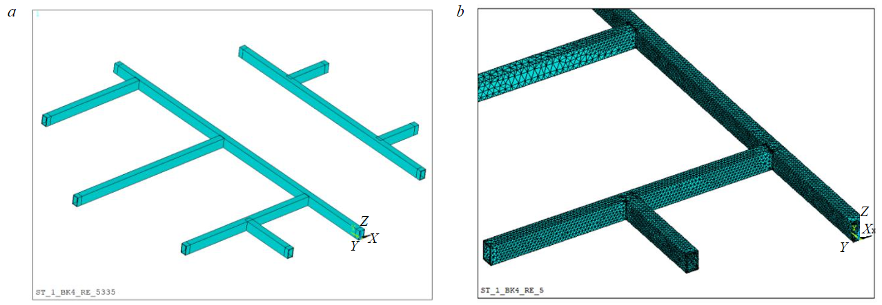
Fig.4. Geometric model of the bunton system with box profile (а) and model fragment with FE mesh (b)
Analysis of numerical results
A series of calculations of the reinforcing deformation at different values of the shaft lining convergence ΔR was carried out. The displacement field UX at the value of the radial displacement of the lining ΔR = 30 mm is presented in Fig.5, where we can observe significant displacements of longitudinal bunton areas R4 and R5 located between the transverse buntons. There is a match of the directions of X axes in Fig.5 and 1. The displacement magnitude UX reaches 192 mm (bunton R4) and –260 mm (bunton R5), which significantly exceeds the convergence value of the shaft lining diameter 2ΔR = 100 mm. This nonlinear effect is due to the strong bending of the parts of the longitudinal buntons.
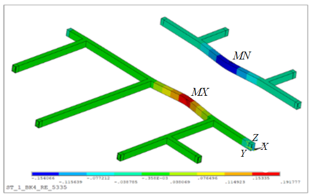
Fig.5. Displacement field UX at ΔR = 30 mm (blue colour corresponds to the value +154 mm, red colour +192 mm)
It is well known that such deformations of the reinforcing cause failure in safe shaft operation much earlier, i.e., at lower values of the lining convergence. Besides, elastic-plastic deformations (and corresponding stress level) can lead to destruction of the welded box body of the bunton beams. In areas with developed plastic deformations, a so-called plastic hinge can occur. In practice, we are more interested in the displacements of the characteristic points of the reinforcing (e.g., at the conductor locations) as a function of the magnitude of the radial lining displacement ΔR.
Figure 6, а shows the dependence of the displacement UX on ΔR for the fixing points of the conductors P3 and P4. Round markers indicate displacement values calculated by engineering formulas (11), which provide overestimated absolute displacements compared to the values obtained by the FEM. This is due to the fact that the numerical solution takes into account the influence of the entire bunton system as well as a possibility of plastic deformations. The sum of the absolute values of these displacements provides the value of the distance reduction between the conductors P3 and P4. It is obvious that already at the displacement of the lining ΔR is more than 15-20 mm, the displacements of the conductors P3 and P4 become unacceptable.
Figure 6, b shows dependences of the distance reduction along the OY axis between the conductors P5 and P6 (curve 1), P6 and P8 (2), P1 and P2 (3). Maximum changes of the distances here are observed for the conductors P1 and P2. In general, these values are less significant than the displacements along the axis OX. It means that maximum displacements of the bunton points, which determine accident-free operation of the reinforcing, occur in the horizontal plane perpendicular to the direction of the main buntons (the displacements in the fixing points of the conductors P3 and P4).
A similar series of calculations was performed for corrosion-prone reinforcing when the box section wall was reduced by 2.4 mm (up to 9.6 mm). Reduction of the wall results in the increased deformations of the bunton system, and quality changes of the deformation behavior of the main longitudinal bunton are possible. In Fig.6, b the dotted line indicates the dependence of the distance reduction along the OY axis between the conductors P6 and P8 at box section thickness of 9.6 mm.
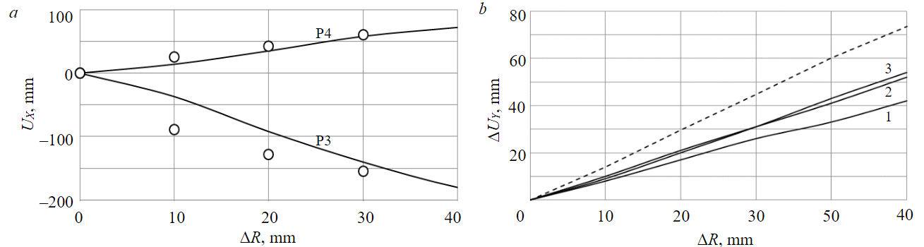
Fig.6. Displacements of the characteristic points of the bunton system
Discussion of the results
Analysis and comparison of the modeling results, engineering calculations and in-situ observations were made based on the data of long-term studies on changes in the distances between the parallel buntons R4 and R5 performed in the interval of the levels N 95-140 of the skip-cage shaft of Berezniki mine. Measurements of the distance between the two buntons were carried out along bold red dotted lines drawn through the points of the plumb lines O2 and O3 (see Fig.1).
The value ∆R is taken from the data of the shaft laser scanning [8], conducted in 2021, with one “west-east” direction chosen for each level. We obtained an estimate of the average rate of diameter change at the intersection with carnallite layers at the site of stationary change in diameter 2.0 mm/year. Since the profiling was carried out in 2013, over 8 years the average diameter change could be about 16 mm. This value was subtracted from the laser scanning data. After the profiling before the end of 2013, the conductors were aligned. The results were taken into account when comparing the calculated and experimental data.
Figure 7 shows the dependences of calculated and experimental measurements of the distance reduction between the buntons for 2013. Maximum discrepancy between the calculated and the experimental data including the aligning is 30 %, the average discrepancy is 10.4 %. It should be noted a quality fit of the calculation data according to the proposed complex method and of the profiling measurements. Repairing and replacing the reinforcing is an extremely labor-intensive process, resulting in high financial costs associated with shaft shutdowns and a corresponding reduction in the productivity of part or the whole potash mine. In the first years of operation of the mine shaft reinforcing located in the salt massif, localized repairs (aligning) are done to correct the curvature of the conductors. Aligning of the reinforcing means adjustment of two reinforcing connection units (flange joints), with displacement of the longitudinal axis in each bunton unit by a certain length, allowing to bring the conductor track to the base value. In each specific case, the aligning time depends on the depth of the level H and on the geomechanical properties of the rock mass at this depth.
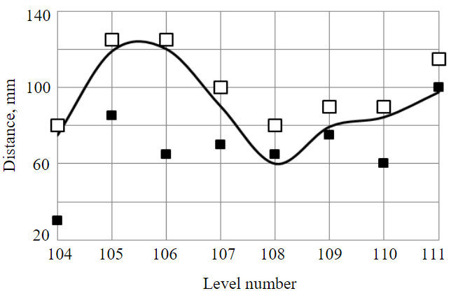
Fig.7. Change of the distance between the buntons: calculation (solid line) and experimental (squares) measurements. Average values of profiling data along the lines O2 and O3 exclusive of the aligning (black squares); including the aligning performed in 2013 (white squares)
For example, mechanical properties of carnallitic rocks are significantly inferior to those of sylvinite or rock salt, so reaching the time Т may occur earlier in the sylvinite-carnallite area rather than in the underlying rock salt area, which is much deeper. In addition, the area of the shaft junction with horizontal workings is also a weakened area. Estimation of the time Т in this area is difficult, as it also depends (apart from the above factors) on the geometry (structural features) of the area of the shaft junction with horizontal workings [10].
Based on the specific rates of change of the shaft diameter obtained by laser scanning [8], results of research data and numerical modeling of the deformation process of the concrete lining as a result of salt mass creep [10], the following conclusions can be drawn:
- for the reinforcing levels located in carnallitic rocks with high rates of change in the shaft diameter, the first aligning should be carried out already in Т = 4-5 years after the operation start, the second one – in 20 years (about 15 years after the first one), the third one – in 50 years (about 30 years after the second one);
- the first aligning for the levels with minimal rates of the diameter change (intersection with rock salt, sylvinite) is necessary after Т = 20-25 years;
- aligning on the remaining levels is necessary in the time range between these two extreme cases.
The proposed integrated approach for each bunton system of a particular shaft needs to be performed anew: to carry out laser monitoring, profiling, to form a new calculation scheme and to perform numerical studies. Of course, the error of forecast calculations may be different for different shafts. The most difficult point is the application of the proposed method for the assessment of the bunton deformations after the performed aligning – it requires additional research.
Thus, practical application of the results of the calculations and the performed research consists in predicting the onset of critical deformations of the rigid reinforcing system with further substantiation of repair works.
Conclusion
This article considers the features and the problems of the rigid reinforcing operation in potash mine shafts, when concrete lining experiences significant deformations when interacting with rock massif. The authors offer the comprehensive assessment of displacements of the characteristic points of the bunton system based on approximate engineering relations, numerical modeling of the deformation process of the bunton system and laser measurements of convergence of the inner surface of the shaft concrete lining.
Numerical modeling of the complete bunton system of rigid reinforcing in 3D-setting at the convergence of the shaft concrete lining was carried out, specific features of the bunton deformation, maximum displacements of the characteristic points were revealed. The authors compared engineering and numerical estimates of the bunton system displacements at different levels with monitoring (profiling) data and laser measurements of the inner surface of the concrete lining of the skip-cage shaft of the potash mine. Based on the estimates of the convergence rates of the shaft concrete lining at the intersection of rock mass layers with different physical and mechanical properties, the forecast estimates of the limiting time of the reinforcing operation have been obtained, after which repair works will be required.
Thus, the comprehensive assessment of the rigid reinforcing deformation at the convergence of the shaft concrete lining allows making correct calculations for determining parameters of rational schemes of the reinforcing structures and the lining of the shafts located in salt massif.
ReferenceS
- Manets I.G., Snegirev Yu.D., Parshintsev V.P. Maintenance and repair of mine shafts. Moscow: Nedra, 1987, p. 327 (in Russian).
- Gerdemeli I., Candas A., Unalan M. Design of Mine Shaft Elevator. Scientific Proceedings IX International Congress “Machines, Technologies, Materials”, 19-21 September 2012, Varna, Bulgaria. Sofia, 2012. Vol. 2, p. 117-120.
- Pleshko M.S., Nasonov A.A., Yagodkin F.I., Privalov A.A. Issues of improvement of vertical shaft planning, construction and reconstruction efficiency. Mining Informational and Analytical Bulletin. 2017. N 8, p. 179-186. DOI: 10.25018/0236-1493-2017-8-0-179-186
- Stradanchenko S.G., Prokopov A.Y., Tkacheva K.E. Probabilistic approach to determination of the tempral loadings on reinforcement of vertical shafts. Mining Informational and Analytical Bulletin. 2012. N 8, p. 61-68.
- Tarasov V.V., Pestrikova V.S., Rusakov M.I. Life cycles of the structure complex of mine shafts of Verkhnekamskoye deposit. Novosibirsk: Nauka, 2021, p. 230 (in Russian).
- Yagodkin F.I., Prokopov A.Yu., Prokopova M.V. Repair of vertical mine shaft lining. News of the Tula State University. Sciences of Earth. 2017. Iss. 3, p. 195-208 (in Russian).
- Samusya V.I., Ilin S.R., Ilina I.S., Ilina S.S. Instability factors of the vehicle-reinforcing system performance in complex mining and geological conditions of vertical shafts. Vestnik Permskogo natsionalnogo issledovatelskogo politekhnicheskogo universiteta. Geologiya. Neftegazovoe i gornoe delo. 2015. N 17, p. 72-80 (in Russian). DOI: 10.15593/2224-9923/2015.17.8
- Tarasov V.V., Aptukov V.N. Deformation monitoring of mine shaft concrete lining by laser scanning. Fiziko-tekhnicheskie problemy razrabotki poleznykh iskopaemykh. 2022. N 5, p. 188-195 (in Russian). DOI: 10.15372/FTPRPI20220518
- Trifanov G.D., Mikryukov A.Yu. Industrial development exploitation based monitoring system lifting vessels in the shafts. Aktualnye problemy povysheniya effektivnosti i bezopasnosti ekspluatatsii gornoshakhtnogo i neftepromyslovogo oborudovaniya. 2016. Vol. 1, p. 49-54.
- Tarasov V.V., Aptukov V.N., Pestrikova V.S. Deformation and failure of concrete lining in vertical shaft at intersections with horizontal tunnels. Journal of Mining Science. 2020. Vol. 56. Iss. 5, p. 726-731. DOI: 10.1134/S1062739120057056
- Konstantinova S.A., Kramskov N.P., Solovev V.A. Some problems of rock mechanics as applied to the mining of diamond deposits in Yakutia. Novosibirsk: Nauka, 2011, p. 223 (in Russian).
- Karasev M.A., Buslova M.A., Vilner M.A., Nguen T.T. Method for predicting the stress-strain state of the vertical shaft lining at the drift landing section in saliferous rocks. Journal of Mining Institute. 2019. Vol. 240, p. 628-637. DOI: 10.31897/PMI.2019.6.628
- Dubinin M.V., Dvornikov B.I. Finite elemet modeling for stress-strain state of the mine trunks reinforcement that it has been made shaft skip. Aktualnye problemy povysheniya effektivnosti i bezopasnosti ekspluatatsii gornoshakhtnogo i neftepromyslovogo oborudovaniya. 2014. Vol. 1, p. 55-60.
- Balek A.Y., Efremov E.Y. Stress-strain state investigation QF mine shaft and horizontal gallery crossing using surveying technique. News of the Tula State University. Sciences of Earth. 2019. Iss. 2, p. 267-279. DOI: 10.25635/IM.2019.29.37273
- Prokopov A.Yu., Prokopova M.V. Engineering of vertical longhole shaft equipment on the basis of laws of functioning of system “an elevating vessel – reinforcement – a trunk”. Mining Informational and Analytical Bulletin. 2012. N 7, p. 78-82.
- Kopytov A.I., Pershin V.V., Voitov M.D., Wetti A.A. The Improvement of the Bunton Construction of Mine-shaft Equipment. The 8th Russian-Chinese Symposium. Coal in the 21st Century: Mining, Processing and Safety, 10-12 October 2016, Kemerovo, Russia. Atlantis Press, 2016, p. 108-110. DOI: 10.2991/coal-16.2016.21
- Sentyabov S.V., Selin K.V., Karamnov D.V. Parameters refining and monitoring for vertical deformations of the axle of mine shaft on the worked space. Problems of Subsoil Use. 2020. N 2 (25), p. 108-115. DOI: 10.25635/2313-1586.2020.02.108
- Ilin S.R., Samusia V.I., Ilina I.S., Ilina S.S. Influence of Dynamic Processes in Mine Hoists on Safety of Exploitation of Shafts with Broken Geometry. Naukovyi visnyk Natsionalnoho hirnychoho universytetu. 2016. N 3, p. 48-53.
- Wolny S., Matachowski F. Analysis of Loads and Stresses in Structural Elements of Hoisting Installations in Mines. Engineering Transaction. 2010. Vol. 58. N 3-4, p. 153-174.
- Kodnyanko E.V. Study of the wear of the profile of the mine shaft conductors. Innovations, Physical Studies and Digitalization in Mining Engineering 2021: Sbornik tezisov VIII Mezhdunarodnoi nauchno-prakticheskoi konferentsii, 22-23 April 2021, Saint Petersburg, Russia. Saint Petersburg: Saint Petersburg Mining University, 2021, p. 189-191.
- Xiao Xing-ming, Li Zhan-fang, Zhang Jun. Study on fault mechanism of shaft hoist steelwork. The 6th International Conference on Mining Science & Technology, 18-20 October 2009, Xuzhou, China. Procedia Earth and Planetary Science, 2009. Vol. 1. Iss. 1, p. 1351-1356. DOI: 10.1016/j.proeps.2009.09.208
- Trifanov G.D., Knyazev A.A., Filatov A.P., Lauk V.V. Experience of Operation of the Mine Winding Plants Equipped with Continuous Monitoring Systems. Monthly Journal of Research and Production. 2019. N 6, p. 52-58. DOI: 10.1016/j.proeps.2009.09.208
- Hanna M., Lloyd A., Tikka T. Improving conveyance side slipper plate design to accommodate higher impact bunton force. Building Tomorrow’s Society, 13-16 June 2018, Fredericton, Canada. Canadian Society for Civil Engineering, 2018, p. ST49-1 – ST49-10.
- Zelenko A.V., Gorbach A.N. Continuous monitoring of safe movement of lifting vessels of shaft barks. Aktualnye problemy povysheniya effektivnosti i bezopasnosti ekspluatatsii gornoshakhtnogo i neftepromyslovogo oborudovaniya: Materialy VI Mezhdunarodnoi nauchno-prakticheskoi konferentsii “Gornaya i neftyanaya elektromekhanika-2019”, 21-24 October 2019, Perm, Russia. Perm: Izd-vo Permskogo natsionalnogo issledovatelskogo politekhnicheskogo universiteta, 2019. Vol. 1, p. 37-43 (in Russian).
- Nikolaitchik M. Determination of skip force effect on guides in mine shaft. Ukrainian School of Mining Engineering, 7-11 September 2020, Berdiansk, Ukraine. E3S Web of Conferences, 2020. Vol. 201. N 01017. DOI: 10.1051/e3sconf/202020101017
- Mikryukov A.Y., Kamenskikh Y.V. Survey and evaluation of the technical condition of lifting vessels. Aktualnye problemy povysheniya effektivnosti i bezopasnosti ekspluatatsii gornoshakhtnogo i neftepromyslovogo oborudovaniya: Materialy VI Mezhdunarodnoi nauchno-prakticheskoi konferentsii “Gornaya i neftyanaya elektromekhanika-2019”, 21-24 October 2019, Perm, Russia. Perm: Izd-vo Permskogo natsionalnogo issledovatelskogo politekhnicheskogo universiteta, 2019. Vol. 1, p. 69-75 (in Russian).
- Pestrikova V.S. Algorithm for calculating the durability of rigid reinforcements of shaft operating under the conditions of Verkhnekamsky deposits of potassium salts. News of the Tula State University. Sciences of Earth. 2019. Iss. 4, p. 332-339.
- Jiannan Yao, Xiaojie Deng, Chi Ma, Tong Xu. Investigation of Dynamic Load in Superdeep Mine Hoisting Systems Induced by Drum Winding. Shock and Vibration. 2021. Vol. 2021. N 4756813. DOI: 10.1155/2021/4756813
- Kachurin N.M., Afanasiev I.A., Pestrikova V.S., Stas P.P. Interactions of vertical shafts with rock massifs by recovery of lining and fasteners and mine shaft equipment. News of the Tula State University. Sciences of Earth. 2020. Iss. 3, p. 290-303.
- Zhuravkov M.A., Nikolaitchik M.A. Finite element modeling of the lifting vessel interaction with the mine shaft structural elements. Mining Mechanical Engineering and Machine-Building. 2021. N 4, p. 15-21.
- Nikolaichik M.A., Zhuravkov M.I. Mathematical modeling of the state of critical elements of the mine hoisting complex. Problemy bezopasnosti na transporte: Materialy XII Mezhdunarodnoi nauchno-prakticheskoi konferentsii, posvyashchennoi 160-letiyu Belorusskoi zheleznoi dorogi, 24-25 noyabrya 2022 g.: v 2 ch. Gomel, Belarus. Belorusskii gosudarstvennyi universitet transporta, 2022. Part 2, p. 228-230 (in Russian).
- Jakubowski J., Fiolek P. Evaluation of Stiffness and Dynamic Properties of a Mine Shaft Steelwork Structure through In Situ Tests and Numerical Simulations. Energies. 2021. Vol. 14. Iss. 3. N 664. DOI: 10.3390/en14030664
- Fiolek P., Jakubowski J. Assessment of the Bending Moment Capacity of Naturally Corroded Box-Section Beams. Materials. 2021. Vol. 14. Iss. 19. N 5766. DOI: 10.3390/ma14195766
- Fiolek P., Jakubowski J. Local buckling of highly corroded hot-rolled box-section beams. Journal of Constructional Steel Research. 2019. Vol. 157, p. 359-370. DOI: 10.1016/j.jcsr.2019.03.009
- Jakubowski J., Fiołek P. Probabilistic structural reliability assessment of underground shaft steelwork. Tunnelling and Underground Space Technology. 2022. Vol. 130. N 104755. DOI: 10.1016/j.tust.2022.104755
- Lalin V.V., Kushova D.A. Geometrically nonlinear deformation and stability problems of plane elastic rods with tension-compression, shear and bending stiffness taken into account. International Journal for Computational Civil and Structural Engineering. 2013. Vol. 9. Iss. 4, p. 178-185.
- Prasolov V.V., Solovev Yu.P. Elliptic functions and algebraic equations. Moscow: Izd-vo Moskovskogo tsentra nepreryvnogo matematicheskogo obrazovaniya, 2022, p. 312 (in Russian).
- Samusia V.I., Iliina I.S., Iliina S.S. Influence of parameters of roller guides on the contact load in the “vessel-reinforcement” for shafts with a broken geometry. Bulletin of PNRPU. Geology. Oil & Gas Engineering & Mining. 2016. Vol. 15. N 20, p. 277-285. DOI: 10.15593/2224-9923/2016.20.8
- Tutyshkin N.D., Gvozdev A.E., Tregubov V.I. et al. Complex problems in plasticity theory. Tula: Tula State University Press, 2015, p. 408.
- Brovko G.L. Approaches to formulation and methods of solving boundary value problems of solid mechanics. Izvestiya MGTU MAMI. 2013. Vol. 7. N 3-1, p. 46-65. DOI: 10.17816/2074-0530-67989
- Morozov E.M., Muizemnek A.Yu., Shadskii A.S. ANSYS in engineer’s hands: Fracture mechanics. Moscow: LENAND, 2014, p. 456 (in Russian).
References
- Manets I.G., Snegirev Yu.D., Parshintsev V.P. Maintenance and repair of mine shafts. Moscow: Nedra, 1987, p. 327 (in Russian).
- Gerdemeli I., Candas A., Unalan M. Design of Mine Shaft Elevator. Scientific Proceedings IX International Congress “Machines, Technologies, Materials”, 19-21 September 2012, Varna, Bulgaria. Sofia, 2012. Vol. 2, p. 117-120.
- Pleshko M.S., Nasonov A.A., Yagodkin F.I., Privalov A.A. Issues of improvement of vertical shaft planning, construction and reconstruction efficiency. Mining Informational and Analytical Bulletin. 2017. N 8, p. 179-186. DOI: 10.25018/0236-1493-2017-8-0-179-186
- Stradanchenko S.G., Prokopov A.Y., Tkacheva K.E. Probabilistic approach to determination of the tempral loadings on reinforcement of vertical shafts. Mining Informational and Analytical Bulletin. 2012. N 8, p. 61-68.
- Tarasov V.V., Pestrikova V.S., Rusakov M.I. Life cycles of the structure complex of mine shafts of Verkhnekamskoye deposit. Novosibirsk: Nauka, 2021, p. 230 (in Russian).
- Yagodkin F.I., Prokopov A.Yu., Prokopova M.V. Repair of vertical mine shaft lining. News of the Tula State University. Sciences of Earth. 2017. Iss. 3, p. 195-208 (in Russian).
- Samusya V.I., Ilin S.R., Ilina I.S., Ilina S.S. Instability factors of the vehicle-reinforcing system performance in complex mining and geological conditions of vertical shafts. Vestnik Permskogo natsionalnogo issledovatelskogo politekhnicheskogo universiteta. Geologiya. Neftegazovoe i gornoe delo. 2015. N 17, p. 72-80 (in Russian). DOI: 10.15593/2224-9923/2015.17.8
- Tarasov V.V., Aptukov V.N. Deformation monitoring of mine shaft concrete lining by laser scanning. Fiziko-tekhnicheskie problemy razrabotki poleznykh iskopaemykh. 2022. N 5, p. 188-195 (in Russian). DOI: 10.15372/FTPRPI20220518
- Trifanov G.D., Mikryukov A.Yu. Industrial development exploitation based monitoring system lifting vessels in the shafts. Aktualnye problemy povysheniya effektivnosti i bezopasnosti ekspluatatsii gornoshakhtnogo i neftepromyslovogo oborudovaniya. 2016. Vol. 1, p. 49-54.
- Tarasov V.V., Aptukov V.N., Pestrikova V.S. Deformation and failure of concrete lining in vertical shaft at intersections with horizontal tunnels. Journal of Mining Science. 2020. Vol. 56. Iss. 5, p. 726-731. DOI: 10.1134/S1062739120057056
- Konstantinova S.A., Kramskov N.P., Solovev V.A. Some problems of rock mechanics as applied to the mining of diamond deposits in Yakutia. Novosibirsk: Nauka, 2011, p. 223 (in Russian).
- Karasev M.A., Buslova M.A., Vilner M.A., Nguen T.T. Method for predicting the stress-strain state of the vertical shaft lining at the drift landing section in saliferous rocks. Journal of Mining Institute. 2019. Vol. 240, p. 628-637. DOI: 10.31897/PMI.2019.6.628
- Dubinin M.V., Dvornikov B.I. Finite elemet modeling for stress-strain state of the mine trunks reinforcement that it has been made shaft skip. Aktualnye problemy povysheniya effektivnosti i bezopasnosti ekspluatatsii gornoshakhtnogo i neftepromyslovogo oborudovaniya. 2014. Vol. 1, p. 55-60.
- Balek A.Y., Efremov E.Y. Stress-strain state investigation QF mine shaft and horizontal gallery crossing using surveying technique. News of the Tula State University. Sciences of Earth. 2019. Iss. 2, p. 267-279. DOI: 10.25635/IM.2019.29.37273
- Prokopov A.Yu., Prokopova M.V. Engineering of vertical longhole shaft equipment on the basis of laws of functioning of system “an elevating vessel – reinforcement – a trunk”. Mining Informational and Analytical Bulletin. 2012. N 7, p. 78-82.
- Kopytov A.I., Pershin V.V., Voitov M.D., Wetti A.A. The Improvement of the Bunton Construction of Mine-shaft Equipment. The 8th Russian-Chinese Symposium. Coal in the 21st Century: Mining, Processing and Safety, 10-12 October 2016, Kemerovo, Russia. Atlantis Press, 2016, p. 108-110. DOI: 10.2991/coal-16.2016.21
- Sentyabov S.V., Selin K.V., Karamnov D.V. Parameters refining and monitoring for vertical deformations of the axle of mine shaft on the worked space. Problems of Subsoil Use. 2020. N 2 (25), p. 108-115. DOI: 10.25635/2313-1586.2020.02.108
- Ilin S.R., Samusia V.I., Ilina I.S., Ilina S.S. Influence of Dynamic Processes in Mine Hoists on Safety of Exploitation of Shafts with Broken Geometry. Naukovyi visnyk Natsionalnoho hirnychoho universytetu. 2016. N 3, p. 48-53.
- Wolny S., Matachowski F. Analysis of Loads and Stresses in Structural Elements of Hoisting Installations in Mines. Engineering Transaction. 2010. Vol. 58. N 3-4, p. 153-174.
- Kodnyanko E.V. Study of the wear of the profile of the mine shaft conductors. Innovations, Physical Studies and Digitalization in Mining Engineering 2021: Sbornik tezisov VIII Mezhdunarodnoi nauchno-prakticheskoi konferentsii, 22-23 April 2021, Saint Petersburg, Russia. Saint Petersburg: Saint Petersburg Mining University, 2021, p. 189-191.
- Xiao Xing-ming, Li Zhan-fang, Zhang Jun. Study on fault mechanism of shaft hoist steelwork. The 6th International Conference on Mining Science & Technology, 18-20 October 2009, Xuzhou, China. Procedia Earth and Planetary Science, 2009. Vol. 1. Iss. 1, p. 1351-1356. DOI: 10.1016/j.proeps.2009.09.208
- Trifanov G.D., Knyazev A.A., Filatov A.P., Lauk V.V. Experience of Operation of the Mine Winding Plants Equipped with Continuous Monitoring Systems. Monthly Journal of Research and Production. 2019. N 6, p. 52-58. DOI: 10.1016/j.proeps.2009.09.208
- Hanna M., Lloyd A., Tikka T. Improving conveyance side slipper plate design to accommodate higher impact bunton force. Building Tomorrow’s Society, 13-16 June 2018, Fredericton, Canada. Canadian Society for Civil Engineering, 2018, p. ST49-1 – ST49-10.
- Zelenko A.V., Gorbach A.N. Continuous monitoring of safe movement of lifting vessels of shaft barks. Aktualnye problemy povysheniya effektivnosti i bezopasnosti ekspluatatsii gornoshakhtnogo i neftepromyslovogo oborudovaniya: Materialy VI Mezhdunarodnoi nauchno-prakticheskoi konferentsii “Gornaya i neftyanaya elektromekhanika-2019”, 21-24 October 2019, Perm, Russia. Perm: Izd-vo Permskogo natsionalnogo issledovatelskogo politekhnicheskogo universiteta, 2019. Vol. 1, p. 37-43 (in Russian).
- Nikolaitchik M. Determination of skip force effect on guides in mine shaft. Ukrainian School of Mining Engineering, 7-11 September 2020, Berdiansk, Ukraine. E3S Web of Conferences, 2020. Vol. 201. N 01017. DOI: 10.1051/e3sconf/202020101017
- Mikryukov A.Y., Kamenskikh Y.V. Survey and evaluation of the technical condition of lifting vessels. Aktualnye problemy povysheniya effektivnosti i bezopasnosti ekspluatatsii gornoshakhtnogo i neftepromyslovogo oborudovaniya: Materialy VI Mezhdunarodnoi nauchno-prakticheskoi konferentsii “Gornaya i neftyanaya elektromekhanika-2019”, 21-24 October 2019, Perm, Russia. Perm: Izd-vo Permskogo natsionalnogo issledovatelskogo politekhnicheskogo universiteta, 2019. Vol. 1, p. 69-75 (in Russian).
- Pestrikova V.S. Algorithm for calculating the durability of rigid reinforcements of shaft operating under the conditions of Verkhnekamsky deposits of potassium salts. News of the Tula State University. Sciences of Earth. 2019. Iss. 4, p. 332-339.
- Jiannan Yao, Xiaojie Deng, Chi Ma, Tong Xu. Investigation of Dynamic Load in Superdeep Mine Hoisting Systems Induced by Drum Winding. Shock and Vibration. 2021. Vol. 2021. N 4756813. DOI: 10.1155/2021/4756813
- Kachurin N.M., Afanasiev I.A., Pestrikova V.S., Stas P.P. Interactions of vertical shafts with rock massifs by recovery of lining and fasteners and mine shaft equipment. News of the Tula State University. Sciences of Earth. 2020. Iss. 3, p. 290-303.
- Zhuravkov M.A., Nikolaitchik M.A. Finite element modeling of the lifting vessel interaction with the mine shaft structural elements. Mining Mechanical Engineering and Machine-Building. 2021. N 4, p. 15-21.
- Nikolaichik M.A., Zhuravkov M.I. Mathematical modeling of the state of critical elements of the mine hoisting complex. Problemy bezopasnosti na transporte: Materialy XII Mezhdunarodnoi nauchno-prakticheskoi konferentsii, posvyashchennoi 160-letiyu Belorusskoi zheleznoi dorogi, 24-25 noyabrya 2022 g.: v 2 ch. Gomel, Belarus. Belorusskii gosudarstvennyi universitet transporta, 2022. Part 2, p. 228-230 (in Russian).
- Jakubowski J., Fiolek P. Evaluation of Stiffness and Dynamic Properties of a Mine Shaft Steelwork Structure through In Situ Tests and Numerical Simulations. Energies. 2021. Vol. 14. Iss. 3. N 664. DOI: 10.3390/en14030664
- Fiolek P., Jakubowski J. Assessment of the Bending Moment Capacity of Naturally Corroded Box-Section Beams. Materials. 2021. Vol. 14. Iss. 19. N 5766. DOI: 10.3390/ma14195766
- Fiolek P., Jakubowski J. Local buckling of highly corroded hot-rolled box-section beams. Journal of Constructional Steel Research. 2019. Vol. 157, p. 359-370. DOI: 10.1016/j.jcsr.2019.03.009
- Jakubowski J., Fiołek P. Probabilistic structural reliability assessment of underground shaft steelwork. Tunnelling and Underground Space Technology. 2022. Vol. 130. N 104755. DOI: 10.1016/j.tust.2022.104755
- Lalin V.V., Kushova D.A. Geometrically nonlinear deformation and stability problems of plane elastic rods with tension-compression, shear and bending stiffness taken into account. International Journal for Computational Civil and Structural Engineering. 2013. Vol. 9. Iss. 4, p. 178-185.
- Prasolov V.V., Solovev Yu.P. Elliptic functions and algebraic equations. Moscow: Izd-vo Moskovskogo tsentra nepreryvnogo matematicheskogo obrazovaniya, 2022, p. 312 (in Russian).
- Samusia V.I., Iliina I.S., Iliina S.S. Influence of parameters of roller guides on the contact load in the “vessel-reinforcement” for shafts with a broken geometry. Bulletin of PNRPU. Geology. Oil & Gas Engineering & Mining. 2016. Vol. 15. N 20, p. 277-285. DOI: 10.15593/2224-9923/2016.20.8
- Tutyshkin N.D., Gvozdev A.E., Tregubov V.I. et al. Complex problems in plasticity theory. Tula: Tula State University Press, 2015, p. 408.
- Brovko G.L. Approaches to formulation and methods of solving boundary value problems of solid mechanics. Izvestiya MGTU MAMI. 2013. Vol. 7. N 3-1, p. 46-65. DOI: 10.17816/2074-0530-67989
- Morozov E.M., Muizemnek A.Yu., Shadskii A.S. ANSYS in engineer’s hands: Fracture mechanics. Moscow: LENAND, 2014, p. 456 (in Russian).