
Selection of the required number of circulating subs in a special assembly and investigation of their performance during drilling of radial branching channels by sectional positive displacement motors
- 1 — Ph.D. Executive General Manager LLO “Perfobore” ▪ Orcid
- 2 — Ph.D., Dr.Sci. Professor Ufa State Petroleum Technological University ▪ Orcid ▪ Elibrary ▪ Scopus
- 3 — Engineer First Division LLO “Perfobore” ▪ Orcid
- 4 — Ph.D. Associate Professor Saint Petersburg Mining University ▪ Orcid ▪ Elibrary ▪ Scopus
Abstract
The task of sludge removal to the surface during construction of directional and horizontal wells and strongly curved radial channels is relevant. For stable operation of technical system “Perfobore”, it is proposed to use a circulating sub that ensures efficient cleaning of channel wellbore from the drilled rock. Two schemes of technical system “Perfobore” are considered, consisting of two seven-meter coiled tubing, a positive displacement motor, a bit and one circulating sub in the first scheme and two subs in the second scheme. For each of the schemes CFD modeling was implemented to determine values of pressure and speed. It was found out that the use of two circulating subs in the assembly is more efficient. In order to confirm the numerical experiment, bench tests were carried out. It was determined that the designed circulating sub can eject up to 25 % of pumped drilling fluid. The bench tests of full-size technical system “Perfobore” for drilling 14-meter channels with two circulating subs showed that the axial load on positive displacement motor produced by hydraulic loader was 3000 N and pressure drop depending on flow rate was 1.5-2.0 MPa. This allows the motor to operate at maximum power.
None
Introduction
The technical system (TS) “Perfobore” for radial drilling of channels is designed for deep perforation of the productive interval during completion of oil and gas wells or their workover. The system enables increased production rate of production wells, improved injectivity of injection wells and elimination of water-gas-oil cones contacts in the near-bottomhole zone through the creation of a system of spiral-shaped perforation channels with a predictable trajectory. The use of TS “Perfobore” enables to cut a “window” in production casing of different durability groups and further perform drilling of branched channels with length over 21 m, with diameter from 58 to 69 mm and radius of curvature from 3.5 to 17.5 m, and also control their trajectories by zenith and azimuth angles, discretely changing the construction of technical system assembly in rig conditions. The technology enables multiple entries into an already drilled channel, e.g. for repairs or for geological and technical measures.
The technical system “Perfobore” (Fig.1) is used during secondary drilling-in of productive horizons to guarantee the penetration beyond the near-bottomhole zone, contaminated by drilling mud filtrate during primary drilling-in. The main elements of the drill string bottom are a bit/cutter, a special sectional positive displacement motor (PDM) [1], a string of steel pipes with specified bending and torsional rigidity and a hydraulic loader capable of operating in damping or oscillator modes [2, 3]. A special sub with orifice is usually installed above the “Perfobore” PDM to regulate the flow of drilling mud to the PDM with a maximum flow rate of 2 l/s and a discharge of some of the mud into the annular space.
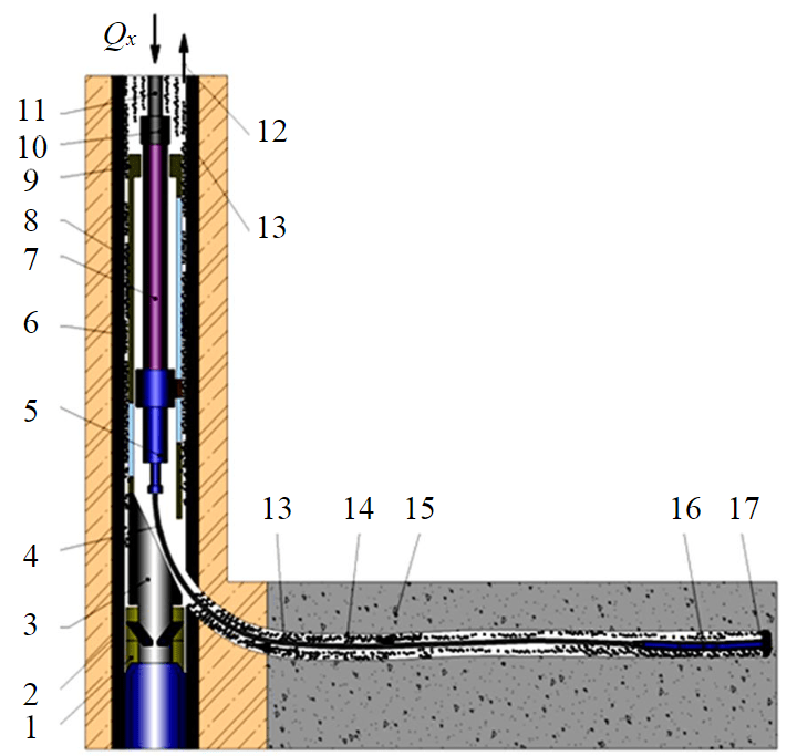
Fig.1. Borehole bottom assembly TS “Perfobore” in a directional channel 1 – anchor; 2 – clutch; 3 – whipstock; 4 – coiled tubing; 5 – hydraulic loader; 6 – cement stone; 7 – pusher; 8 – casing; 9 – modular frames; 10 – overflow valve; 11 – tubing/coiled tubing; 12 – upward flow; 13 – drilled rock; 14 – perforation channel; 15 – productive formation; 16 – positive displacement motor; 17 – bit
The problem of sludge transport during directional well construction and qualitative wellbore cleaning has been widely discussed in Russian and foreign scientific and technical literature. Thermohydraulic processes during well drilling are studied in works of Russian scientists: A.G.Avetisova, F.A.Akzamova, E.A.Akopova, A.I.Bulatova, E.P.Varlamova, L.K.Gorshkova, M.A.Goldshtik, N.A.Grigoryana, V.I.Isaeva, A.G.Kalinina, V.V.Kafarova, B.B.Kudryashova, E.G.Leonova, A.M.Lihushina, A.H.Mirzadzhanzade, M.R.Mavlyutova, N.I.Nikolaeva, V.S.Prokopenko, V.I.Ryabchenko, R.H.Sannikova, L.I.Sedova, N.I.Slyusareva, B.P.Ustimenko, R.I.Shishchenko, V.I.Shchukina and others.
In the foreign literature, the most detailed consideration of sludge transport processes in small diameter horizontal boreholes is given by H.Zhang [4], S.Sayindla [5, 6], О.Agwu [7] and B.Basahmin [8]. The thesis [4] presents the results of both experimental investigations on a special test bench and numerical simulation. In [5, 7] there is a comprehensive review of experimental, numerical investigations of sludge settling velocity in drilling mud carried out by researchers during last decades. The paper [8] gives a review of analytical and numerical models of wellbore cleaning in horizontal and vertical wells. It also presents a numerical model of horizontal wellbore cleaning and a comparative analysis of sludge removal process in horizontal and vertical wells. Work [9] gives recommendations for using Monte Carlo simulation method. The method was applied for the comparison of simple probabilistic investigation of traditional models for well circulating in order to evaluate quantitatively the level of certainty/uncertainty in the calculation procedure. Despite of the satisfactory result for a particular type of well, the author describes in the conclusions that in the case of uncertain input data there will be some degree of uncertainty in the well circulating optimization parameters.
The article [10] investigated the influence of different drilling process parameters on sludge removal efficiency. Three most widely used models of sludge transport (Rudi-Shindu, Hopkins, Tobenna) have been compared based on sensitivity analysis of drilling process parameters influencing sludge removal. It has been found out that the considered models are not suitable for horizontal wells because they do not take into account the wellbore cross-sectional profile. The work [11] proves the necessity to take into account geomechanical processes taking place in near-well zone, technological and technical factors such as vibrations and rotation of drill string, formation of grooves during assembly running, pressure pulsations when starting and stopping pumps, hydrostatic and hydrodynamic pressure of drilling mud, its formulation and properties influencing the degree of well cleaning.
Works [12, 13] show the results of experimental investigations on estimation of sludge removal efficiency for three types of drilling mud. The effect of three parameters: viscosity, flow velocity and zenith angle has been considered. It was found that the use of highly viscous drilling mud in turbulent flow regimes increases the efficiency of sludge removal. However, increasing the viscosity in laminar and transitional regimes gradually or drastically reduces the efficiency of sludge removal. As the zenith angle increases from 60 to 90°, the efficiency of sludge removal increases. At the same time, the paper [14] deals with wellbore cleaning in horizontal and directional wells during coiled tubing drilling, and in particular the effect of the rotation of the drill string on it. It is shown that at average speed of the drilling fluid flow in the annular space (0.56-0.69 m/s) the wellbore cleaning efficiency increases by 68 %. However, at lower speed of the drilling fluid flow in the annular space and zenith angles less than 60° the influence of drill string rotation is less significant. It is concluded that the turbulent flow regime is not effective for cleaning horizontal wells. Similar results were obtained by the authors of works [15, 16] on the experimental test bench, who demonstrated intense difficulty of sludge removal to the surface at the critical well zenith angle 55°.
The article [17] provides a relatively simple and fast graphical method for determining the minimum sludge particles speed in the drilling mud for efficient wellbore cleaning. A distinctive feature of the approach adopted in hydrodynamic modelling of sludge transport in works [18-20] is the use of non-spherical sludge particles. It was noted that the most intensive deposition of sludge occurs at the section of transition from inclined wellbore to vertical one. The works [21, 22] show the urgency of studying sludge transport processes in connection with the development of technologies for construction of wells with complicated profiles. Work [23] shows the results of numerical hydrodynamic simulation of sludge transportation process in a horizontal well. It is established that when the density of drilling mud increases by two times, sludge sedimentation decreases by 32.9 %, while drill string stress and pressure loss increase by 4.59 and 5.97 %.
As can be seen from the review of works devoted to hydrodynamic processes during oil and gas wells drilling, in investigation of sludge transportation process in small diameter wells and deep radial perforation channels, despite the great number of publications in this area, the issues of scientific and methodological support for open wellbore cleaning are still urgent. What is especially important – there are no appropriate analytical solutions and calculation methods for practical application by engineering and technological personnel of oilfield service companies.
Research setting
The main feature of sludge transportation to surface during radial perforating drilling with TS “Perfobore” is the necessity to take into account technical capabilities of special sectional PDM of small diameter (43-49 mm), small gap in annular space of perforation channel (7-10 mm) and low speed of upward flow of drilling mud inside the casing. Sludge particles have smaller size than ones in conventional drilling, because of very small diameter of the abrasive-cutting drilling tool, significantly lower loads on the bit (2-6 kN) and high rotation rate of the spindle in the small-size bottomhole motor (500-800 rpm) [1].
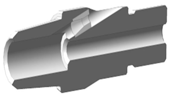
Fig.2. Circulating sub in sectional view
The circulating sub (CS) (Fig.2), due to an upward facing orifice with a special profile and increased mud flow, acts as a hydro-ejector, accelerating the drilling mud flow up the annulus. At the same time, the bottomhole pressure in the wellbore interval below the sub decreases, which in combination with drill string tension and activation of hydraulic loader operation in oscillator mode contributes to decreased probability of possible differential sticking [24]. Periodic activation of this mode allows improving circulating of horizontal channel section and avoiding accumulation of sludge in annular space of the drilled channel. To clean the bit and effectively remove the drilled rock from the bottomhole (especially when drilling extended channels of small diameter) and its subsequent removal to the surface, it is necessary to provide an upward flow speed exceeding the drop speed of solid particles, which is calculated in transient and turbulent modes of particle flow according to Rittinger’s formula.
The inability to rotate the coiled tubing (CT) in the channel during drilling with TS “Perfobore” also significantly complicates the proper cleaning of the wellbore from the drilled sludge. This, in turn, can lead to sludging [24, 25], risks of sticking [26] and reduction of commercial drilling speed [27, 28]. The absence of drill string rotation does not give a reliable answer about the proper cleaning of radial channel from the drilled rock [29, 30]. The problem of sludge removal in intervals with zenith angles of 30-60° is also aggravated by the presence of a horizontal section in the drilled channel, which remains relevant for traditional horizontal wellbore drilling [31, 32].
Methodology
Mathematical modelling of sludge removal
Let us consider hydrodynamic process of sludge removal in annular space during drilling of a section for a setting of the zenith angle in a deep radial perforation channel with TS “Perfobore”. The modern tendency in analyses of processes, occurring during well drilling, is using of finite elements method, more exactly CFD modelling (Computational Fluid Dynamics modeling). Engineers all over the world use many tools for CFD calculations; however, the international long-term experience of using this type of software shows the superiority of the Ansys CFX for this type of tasks [19, 33, 34].
Two types of schemes were used in the calculations (Fig.3). The installation locations and number of circulating subs were chosen according to the design features of the assemblies. Circulating sub can be installed above PDM as well as between pipes transferring load from hydraulic loader to PDM and bit.
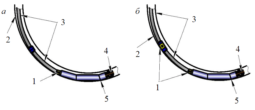
Fig.3. Schemes of borehole bottom assembly: scheme 1 with one CS in radial perforation channel (a); scheme 2 with two CS installed: one above the PDM, the other between the lower and upper pipe in the radial perforation channel (b) 1 – circulating sub; 2 – channel wall; 3 – coiled tubing; 4 – bit; 5 – PDM
The following inputs and assumptions are used in the calculation and are the same for both calculation schemes:
- Channel length of 14 m is selected for accident-free passage of the motor with two skew angles; curvature radius is 8 m; channel diameter is from 58 to 69 mm depending on the size of the PDM used.
- Abrasive-cutting bit by “Perfobore” with diameter of 69 mm.
- Special small-size positive displacement motor with diameter of 49 mm and two sections of working bodies with 9´10 pitch, curvature angles are 5° and a special spindle section.
- External circulating sub with diameter of 49 mm (4.2 mm internal orifice in the nozzle).
- Steel coiled tubing; outside diameter is 28 mm; wall thickness is 3 mm.
- In each scheme, the outer and inner roughness of the assemblies were assumed to be Ra 6.3 μm; the roughness of the drilled channel walls in the carbonate reservoir is 3 mm.
- The length of the coiled tubing is chosen for ease of assembly arrangement at the wellhead, as the height of the derrick does not allow the whole assembly to be lowered and mounted on the scaffolding.
Values of boundary condition parameters for schemes 1 and 2 of mathematical model and numerical solution: inlet pressure is 4.7 and 9.3 MPa; average speed of liquid flow in channel 2.5 and 1.2 m/s; mass flow rate of liquid is 3-6 kg/s. The inlet pressure is specified as the pressure in the system varies depending on the channel length, density and friction loss in the pipes. According to the basic provisions of GOST 6134-2007 single phase flow (technical water) in stationary formulation with density 998 kg/m3 is considered.
Numerical investigations were carried out using a system of Navier – Stokes equations averaged by Reynolds (continuity and motion equations), a closed k-ε turbulence model (turbulent kinetic energy equation and turbulent kinetic energy dissipation rate equation) [35]. To solve the problem on the geometric model made in the CAD system Kompas-3D, first of all a finite element mesh is generated.
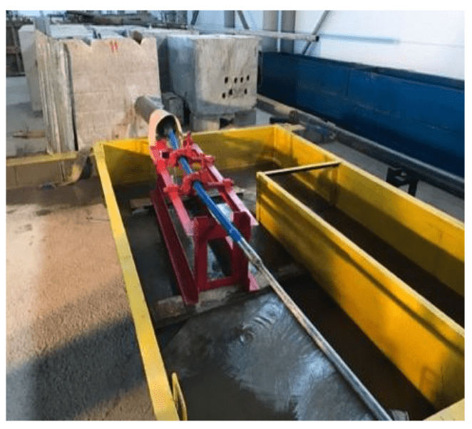
Fig.4. Bench testing of PDM operation
Varying values of liquid mass flow rate from 3 to 6 kg/s are determined by the fact that rated characteristics of special small size PDM, used for drilling of radial channel without circulating sub, allow efficient operation at the flow rate of 2 kg/s [1], and installation of circulating (bleeding) subs in borehole bottom assembly allows increasing the total mass flow rate up to 6 kg/s. As research [1] shows, it is not necessary to increase mass flow rate more than 6 kg/s, moreover, it requires more expensive pumping units, which are difficult to find at remote fields [36].
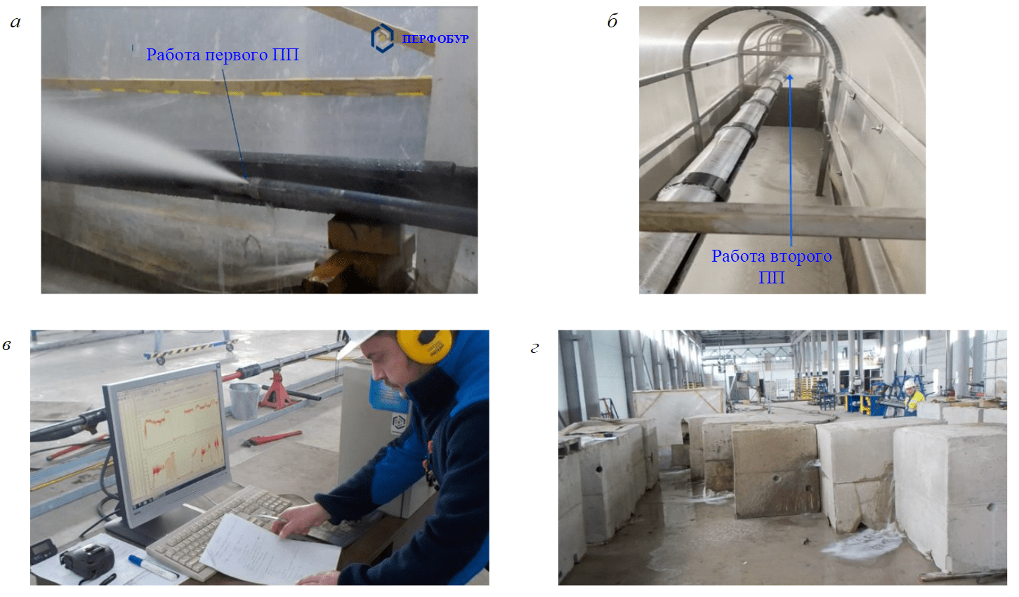
Fig.5. Bench tests of the assembly in configuration with one (a) and two (b) CS; operator workplace for controlling and monitoring the test bench process (c); special blocks, manufactured according to API 19B standards, for carrying out the test (d)
Carrying out bench and field tests
In preparation for the bench test (Fig.4), the assemblies were arranged: bit, PDM and CS, as well as the assembly without CS. Since the PDM are tested at the factory before they are shipped to the customer, each motor has a known dependence of the spindle shaft rotation frequency on different mass flow rates of this liquid. The motor was started up on a “Perfobore” universal test bench at a rated flow rate of 2 l/s, then a value corresponding to the factory tests was obtained using an AKIP-9202 laser tachometer to measure the rotation frequency. Further, CS was installed into the assembly and the PDM was also started up with a gradual increase in flow rate at the pumping station SIN-46 until the shaft rotation frequency began to correspond to the values obtained in the previous experiment.
The next stage of the bench tests was to analyze the performance of the assembly with CS in the channel when drilling sand-cement blocks (Fig.5). The dimensions of the blocks, their varying hardness and abrasivity, and their arrangement with calculated spacing between them allowed, firstly, the simulation of rock interference and, secondly but most valuable, gave the ability to control the trajectory and measure the drilling mud flow rate along the entire length of the channel. For this purpose full-scale TS “Perfobore” was assembled for drilling of 14-meter channels in special blocks, with two CS installed in the assembly according to the scheme shown in Fig.3, b. Mass flow rate of drilling fluid was controlled in the range of 3-6 kg/s, axial load on PDM produced by hydraulic loader was 3000 N, and pressure drop on PDM depending on flow rate was 1.5-2.0 MPa, which corresponds to rated values at optimum power.
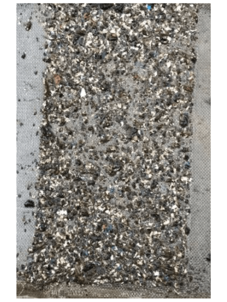
Fig.6. Photograph of the screen of the intake tank with the sludge from the bottomhole of the channel
In order to model flow regime and evaluate reliability and efficiency of TS as a whole, the bench is equipped with control and measuring instruments (CMI): pressure sensors DMP 330L, flow rate meter, which is duplicated by the CMI of SIN-46 pumping unit, as well as axial load sensors (mesdose with pressure transducer MPD-01VD and DVST type vibration sensors), working fluid temperature is registered by Fluke pyrometer.
After successful completion of the bench tests, the equipment and technology were tested in wells. The rate for set of channel curvature was 8-10° per meter of penetration, which corresponded to a curvature radius of 7-9 m and ensured investigation of the whole range of channel zenith angle variation in the intervals from 7 to 120-150° (where 7° is the initial angle of whipstock). Measurement of the trajectory was performed by small-size autonomous inclinometers of the magnetometering “Kvartz-36” and gyroscopic TwinGyro. The presence of sludge in the channels drilled with different curvature was assessed visually and by weighing it during drilling pauses when the special blocks were relocated (Fig.6)
Discussion of the results
Pressure and speed distributions are obtained after mathematical modelling and bench testing (see Table). Figure 7 shows visualization of modelling for design scheme with one CS at 3 kg/s, the required values of speed and pressure are indicated by the marks.
Pressure and speed distribution during modelling in TS “Perfobore”
|
Mass flow rate,kg/s |
Pressure, MPa |
Speed, m/s |
||||||||||
|
Scheme 1 |
Scheme 2 |
Scheme 1 |
Scheme 2 |
|||||||||
|
Between CT |
Above PDM |
At the bit |
Between CT |
Above PDM |
At the bit |
Between CT |
Above PDM |
At the bit |
Between CT |
Above PDM |
At the bit |
|
|
3 |
0.107 |
0.374 |
0.091 |
0.202 |
0.253 |
0.096 |
1.7 |
24 |
0.65 |
15 |
15 |
1.5 |
|
4 |
1.111 |
0.425 |
0.081 |
0.354 |
0.334 |
0.091 |
2.1 |
25 |
2.8 |
23 |
22 |
2 |
|
5 |
0.121 |
0.607 |
0.081 |
0.506 |
0.607 |
0.091 |
2.5 |
27 |
3.5 |
25 |
30 |
1.8 |
|
6 |
0.121 |
0.851 |
0.111 |
0.557 |
0.709 |
0.081 |
3.7 |
35 |
4.3 |
30 |
32 |
2.2 |
Analyzing the results of calculations, it can be concluded that the use of assemblies with two CS is efficient, as the speed of fluid flow in problematic intervals is significantly higher in the space between the coiled tubing and the channel walls. The results obtained are consistent with those of [37, 38]. In order to confirm this hypothesis bench and then field tests were conducted. As a result of bench tests at the first stage, it was determined that the developed CS can discharge up to 25 % of drilling fluid.
Conclusion
Experimental investigations have shown that the mathematical model correctly reproduces the character of liquid motion in the channel and provides high correlation with the experimental data. The mathematical modelling and bench tests allowed the authors to conduct pilot tests with minimal risks, first of all for themselves and the created technology, and after their successful completion to proceed to large-scale field works.
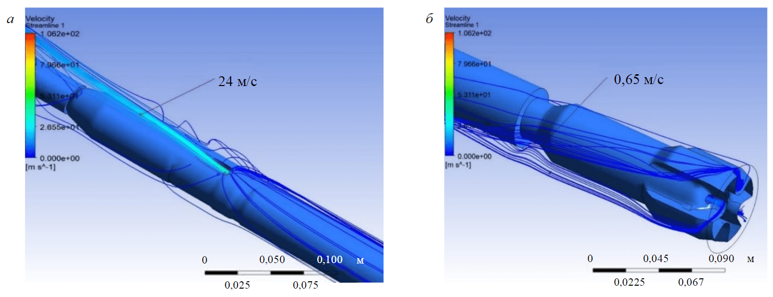
Fig.7. Visualization of fluid flow from CS (a) and bit (b) during drilling the channel
The results of calculations to ensure reliable circulating of the channel were verified during bench and field tests at the wells of PAO ANK “Bashneft”, OOO “Lukoil-Komi”, OAO “Nokratojl”, PAO “Novatek”, OOO “Gazpromneft-Yamal” fields, PAO “Tatneft”, OOO “Novatek-Tarkosaleneftegaz”, AO “NK “Neftisa”, JV OOO Uz-Kor Gas Chemical (The Republic of Uzbekistan), OOO Sanoat Energetika Guruhi (The Republic of Uzbekistan), TOO KAZPETROL GROUP (The Republic of Kazakhstan), Creative Oil & Gas Operation (USA). To ensure normal operation of TS “Perfobore” and carry sludge to the surface, special assemblies with two CS were used, and at some wells, a clay-free biopolymer drilling mud with special properties was used.
References
- Lyagov I.A., Baldenko F.D., Lyagov A.V. et al. Methodology for calculating technical efficiency of power sections in small-sized screw downhole motors for the “Perfobur” system. Journal of Mining Institute. 2019. Vol. 240, p. 694-700. DOI: 10.31897/PMI.2019.6.694
- Dvoynikov M.V. Technology of oil and gas wells drilling by downhole drilling motors. London: LAP LAMBERT Academic Publishing, 2013, p. 18-29.
- Dvoinikov M.V., Muraev Y.D. Technical and technological solutions to ensure stability of downhole drilling motors. Journal of Mining Institute. 2016. Vol. 218, p. 198-205 (in Russian).
- Hongyang Zhang. Experimental Study of Cuttings Transport in Coiled Tube Micro-Borehole Drilling: Thesis for degree of doctor of philosophy of Curtin University. Perth: Curtin University, 2018, p. 168. URL: http://hdl.handle.net/20.500.11937/68365 (accessed 10.05.2022).
- Sayindla S., Lund B., Ytrehus J.D., Saasen A. Hole-cleaning performance comparison of oil-based and water-based drilling fluids. Journal of Petroleum Science and Engineering. 2017. Vol. 159, p. 49-57. DOI: 10.1016/j.petrol.2017.08.069
- Sayindla S., Lund B., Ytrehus J.D., Saasen A. CFD Modelling of Observed Cuttings Transport in Oil-Based and Water-Based Drilling Fluids. SPE/IADC Drilling Conference and Exhibition, 14-16 March 2017, The Hague, The Netherlands. OnePetro, 2017. N SPE-184660-MS, p. 1556-1567. DOI: 10.2118/184660-MS
- Agwu O.E., Akpabio J.U., Alabi S.B., Dosunmu A. Settling velocity of drill cuttings in drilling fluids: A review of experimental, numerical simulations and artificial intelligence studies. Powder Technology. 2018. Vol. 339, p. 728-746. DOI: 10.1016/j.powtec.2018.08.064
- Basahmin B., Saeid N.H., Alusta G., Zahran E-S.M.M. Review on hole cleaning for horizontal wells. Journal of Engineering and Applied Sciences. 2017. Vol. 12. N 16, p. 4697-4708.
- Tabatabaee Moradi S.S. A probabilistic study on hole cleaning optimization. Journal of Mining Institute. 2022. Vol. 258, p. 956-963. DOI: 10.31897/PMI.2022.67
- Shiddiq A.M.I., Toro B.C., Syafri I. et al. A Comprehensive Comparison Study of Empirical Cutting Transport Models in Inclined and Horizontal Wells. Journal of Engineering and Technological Sciences. 2017. Vol. 49. Iss. 2, p. 275-289. DOI: 10.5614/j.eng.technol.sci.2017.49.2.9
- Blinov P.A. Determining the Stability of the Borehole Walls at Drilling Intervals of Loosely Coupled Rocks Considering Zenith Angle. Journal of Mining Institute. 2019. Vol. 236, p. 172-179. DOI: 10.31897/PMI.2019.2.172
- Piroozian A., Ismail I., Yaacob Z. et al. Impact of drilling fluid viscosity, velocity and hole inclination on cuttings transport in horizontal and highly deviated wells. Journal of Petroleum Exploration and Production Technology. 2012. Vol. 2. Iss. 3, p. 149-156. DOI: 10.1007/s13202-012-0031-0
- Piroozian A., Isshan I. Cuttings Transport in Horizontal and Highly Deviated Wellbores. Jurnal Teknologi. 2011. Vol. 56, p. 1-14. DOI: 10.11113/jt.v56.50
- Muherei M.A., Basaleh S.S., Bamaga M.A. Hole Cleaning in Horizontal and Highly Deviated Wellbores Drilled with Coiled Tubing Drill Pipe Rotation. Draw Back Is It Significant. International Research Journal of Engineering and Technology. 2015. Vol. 2. Iss. 9, p. 2280-2286.
- Kadochnikov V.G., Dvoynikov M.V. Development of Technology for Hydromechanical Breakdown of Mud Plugs and Improvement of Well Cleaning by Controlled Buckling of the Drill String. Applied Science. 2022. Vol. 12. Iss. 13. N 6460. DOI: 10.3390/app12136460
- Kadochnikov V.G., Dvoynikov M.V., Blinov P.A. Influence of the Drill String Spatial Form on Transport of Cuttings in Directional Wells. Bulletin of the Association of Drilling Contractors. 2020. N 2, p. 12-19 (in Russian).
- Joshi S., Braisare A. Graphical method to determine minimum cutting fluid velocity for effective hole cleaning. International Research Journal of Engineering and Technology. 2017. Vol. 4. Iss. 6, p. 1684-1689.
- Epelle E.I., Gerogiorgis D.I. A CFD investigation of the effect of particle sphericity on wellbore cleaning efficiency during oil and gas drilling. Computer Aided Chemical Engineering. 2018. Vol. 43, p. 127-132. DOI: 10.1016/B978-0-444-64235-6.50024-3
- Epelle E.I., Gerogiorgis D.I. A multiparametric CFD analysis of multiphase annular flows for oil and gas drilling applications. Computers & Chemical Engineering. 2017. Vol. 106, p. 645-661. DOI: 10.1016/j.compchemeng.2017.08.011
- Epelle E.I., Gerogiorgis D.I. CFD modeling and simulation of drill cuttings transport efficiency in annular bends: Effect of particle sphericity. Journal of Petroleum Science and Engineering. 2018. Vol. 170, p. 992-1004. DOI: 10.1016/j.petrol.2018.06.041
- Xiaofeng Sun, Kelin Wang, Tie Yan et al. Effect of drillpipe rotation on cuttings transport using computational fluid dynamics (CFD) in complex structure wells. Journal of Petroleum Exploration and Production Technology. 2014. Vol. 4. Iss. 3, p. 255-261. DOI: 10.1007/s13202-014-0118-x
- Wang Kelin, Yan Tie, Sun Xiaofeng et al. Review and Analysis of Cuttings Transport in Complex Structural Wells. The Open Fuels & Energy Science Journal. 2013. Vol. 6. Iss. 1, p. 9-17. DOI: 10.2174/1876973X20130610001
- Zakerian A., Saratraz S., Tabzar A. et al. Numerical modeling and simulation of drilling cutting transport in horizontal wells. Journal of Petroleum Exploration and Production Technology. 2018. Vol. 8. Iss. 2, p. 455-474. DOI: 10.1007/s13202-018-0435-6
- Lyagov I.A., Gubaidullin A.G., Lyagov A.V. et al. Forecasting the Risks of Jamming to Exclude the Possibility of Stitching the Technical System “Perfobur” while Drilling Branched Channels in Terrigenous Reservoirs. Bulletin of the Tomsk Polytechnic University. Geo Assets Engineering. 2019. Vol. 330. N 10, p. 126-136 (in Russian). DOI: 10.18799/24131830/2019/10/2304
- Reichert R.S., Tsukrenko M.S., Organov A.S. Technical and technological solutions for cleaning directional and horizontal wellbores from sludge. Neft. Gas. Novacii. 2016. N 3, p. 28-35 (in Russian).
- Nazari T., Hareland G., Azar J.J. Review of Cuttings Transport in Directional Well Drilling: Systematic Approach. SPE Western Regional Meeting, 27-29 May 2010, Anaheim, California, USA. OnePetro, 2010. N SPE-132372-MS. DOI: 10.2118/132372-MS
- Aleksandrov S.S., Lugumanov M.G. Regime Regulating of Well Clean-Up During Drilling. Burenie & neft. 2013. N 2, p. 36-38 (in Russian).
- Ulyasheva N.M., Leusheva E.L., Galishin R.N. Development of the drilling mud composition for directional wellbore drilling considering rheological parameters of the fluid. Journal of Mining Institute. 2020. Vol. 244, p. 454-461. DOI: 10.31897/PMI.2020.4.8
- Pushmin P.S., Romanov G.R. Problems of Slant Directed Wells Cleaning. The Earth Sciences and Subsoil Use. 2014. N 3 (46), p. 56-60 (in Russian).
- Vromen Т.G.M. Control of stick-slip vibrations in drilling systems: PhD thesis. Eindhoven University of Technology. Eindhoven, 2015, p. 256.
- Xiaohua Zhu, Liping Tang, Qiming Yang. A Literature Review of Approaches for Stick-Slip Vibration Suppression in Oilwell Drillstring. Advances in Mechanical Engineering. 2014. Vol. 6. N 967952. DOI: 10.1155/2014/967952
- Agzamov F.A., Akbulatov T.O., Khabibullin I.A. et al. Influence of rheological properties of the flushing fluid on sludge transport in a horizontal wellbore. Oil Gas Territory. 2008. N 9, p. 16-18 (in Russian).
- Tie Yan, Jingyu Qu, Xiaofeng Sun et al. Investigation on horizontal and deviated wellbore cleanout by hole cleaning device using CFD approach. Energy Science & Engineering. 2019. Vol. 7. Iss. 4, p. 1292-1305. DOI: 10.1002/ese3.346
- Smorkalov D.V., Tyutyaev A.V., Shterenber A.M., Gorshkalev A.A. Modeling of the egress of a drilling liquid from the nozzle of a drill bit with Ansys Fluent. IOP Conference Series: Materials Science and Engineering. 2017. Vol. 177. N 012067. DOI: 10.1088/1757-899X/177/1/012067
- Nikitin V.I. Problem solution analysis on finding the velocity distribution for laminar flow of a non-linear viscous flushing fluid in the annular space of a well. Journal of Mining Institute. 2022. Vol. 258, p. 964-975. DOI: 10.31897/PMI.2022.93
- Sidorkin D.I., Kupavykh K.S. Justification on Choosing Screw Pumping Units as Energy Efficient Artificial Lift Technology. ENERGETIKA. Proceedings of CIS higher education institutions and power engineering associations. 2021. Vol. 64. N 2, p. 143-151. DOI: 10.21122/1029-7448-2021-64-2-143-151
- Heshamudin N.S., Katende A., Rashid H.A. et al. Experimental investigation of the effect of drill pipe rotation on improving hole cleaning using water-based mud enriched with polypropylene beads in vertical and horizontal wellbores. Journal of Petroleum Science and Engineering. 2019. Vol. 179, p. 1173-1185. DOI: 10.1016/j.petrol.2019.04.086
- Burke J., Harrison C., Gamarra F. et al. Thru-Tubing Cleanouts and Acidization in Unconventional Wells. SPE/ICoTA Well Intervention Conference and Exhibition, 22-23 March 2022, The Woodlands, Texas, USA. OnePetro, 2022. N SPE-209026-MS. DOI: 10.2118/209026-MS