
Mathematical modeling of the electric field of an in-line diagnostic probe of a cathode-polarized pipeline
- 1 — Ph.D., Dr.Sci. Professor Saint Petersburg Mining University ▪ Orcid
- 2 — Ph.D. Saint Petersburg Mining University ▪ Orcid
- 3 — Ph.D., Dr.Sci. Principal researcher Schmidt Institute of Physics of the Earth of the Russian Academy of Sciences ▪ Orcid ▪ Elibrary ▪ Scopus
- 4 — Postgraduate Student Saint Petersburg Mining University ▪ Orcid
Abstract
A mathematical model of the in-line control of the insulation resistance state for cathodically polarized main pipelines according to electrometry data is considered. The relevance of the work is caused by the opportunity to create in-line internal isolation defects indicators of the main pipelines for transported liquids that are good conductors and expand the functionality of monitoring and controlling cathodic protection systems of the main pipelines. Features of the mathematical model are: consideration of the electric conductivity of transported liquid influence on electric field distribution; consideration of the influence of external and internal insulating coating resistance; use of the electric field of an in-line diagnostic probe for quality control of internal insulation. Practical significance consists in the development of modeling methods for control subsystems of main pipeline protection against corrosion and the development of special mathematical and algorithmic support systems for monitoring and controlling the operating modes of the cathodic protection station of main pipelines.
None
Introduction
Main pipelines (MP) are prone to corrosion, which is the main cause of pipeline failures and downtime [1, 2]. Corrosion occurs due to the influence of mechanical impurities [3-5], stray currents of different nature [6], pipeline and ground deformation [7-9], inner and outer insulation coating defects, etc. In practice, ultrasonic and magnetometric methods are widely used for pipeline diagnostics [10, 11]. Ultrasonic methods of nondestructive testing are developing both towards optimization of the number and spatial location of sensors [12] and towards more complex processing of reflected signals [13-15]. External insulation condition monitoring [16, 17] is usually performed manually using special equipment [18-20], but remote methods of nondestructive testing are also being intensively developed [21]. It is difficult to assess the quality of in-line insulation outside the pipe due to the properties of the pipe metal shielding the excited field. A solution in such cases is the use of in-line tools (probes) [22]. Magnetometric [23] and ultrasonic methods of pipe metal quality evaluation are used for in-line inspection. The use of an in-line source of direct electric current in highly conductive transported media (salt solutions, water, some products of multi-tonnage chemical productions, etc.) and water-oil media [24, 25] makes it possible to investigate the mutual influence of internal insulation quality and the gradient of electric field measured by the probe. Such a sufficiently operative estimation of the internal insulation quality contributes to the development of special mathematical and algorithmic support for the monitoring and control systems of cathodic protection stations (CPS) in MP.
The purpose of this work is to develop a mathematical model for in-line monitoring of the insulation resistance state of cathodically polarized MP using electrometric data. The relevance of the work is determined by the possibility of creating in-line indicators of internal insulation defects in MP and extending the functionality of monitoring and control systems of CPS of MP at the expense of this information. For this purpose, the following tasks have been solved: the constructed differential mathematical model of the electric field of the CPS and in-line electric probe by a method of fictitious sources has been reduced to a discrete model in the form of a system of linear algebraic equations (SLAE); influence of internal isolation failure on the gradient of the electric field of the in-line probe has been studied by means of a computational experiment.
Methods
Ensuring the required quality of corrosion protection for operating oil and gas equipment [26-28] includes maintaining the required level of protective cathodic potential on the metal surface. Modern computing technologies, including neural networks, are used to solve this problem [29]. A mathematical model of the cathodically polarized MP should describe the distribution of currents and potentials along the entire length of the section to be protected by the CPS. The realization of the model allows calculating the values of currents and voltages in the pipe and on the interfaces “pipe – ground” and “pipe – transported liquid” [30-32]. Initial data for the calculations are the electric properties of all current spreading media, auxiliary current strength CPS, geometrical characteristics of the MP, and also the spatial coordinates of the MP, anode earth electrode, and current drainage point. Note that due to the impossibility of exact determination in time and space of all physical quantities describing the real operation of a MP, an absolutely accurate description of such a system is fundamentally impossible [16]. Nevertheless, as the analysis of scientific research shows [17, 33], in calculations, such a model of MP medium as homogeneous isotropic half-space with averaged (and constant) specific ground conductivity is used. Therefore, in order to achieve the purpose of this work, it is necessary to develop a mathematical model adequate to the practice of the direct problem of electromagnetic field distribution of direct DC of MP cathode protection system in homogeneous medium of “ground – external insulation – metal – internal insulation – transported liquid – probe” type and conduct a computational experiment to study the influence of transient resistance of internal insulation on current distribution in the system.
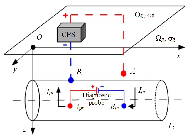
Fig.1. Inclusion of a diagnostic probe in the cathodic protection scheme of a MP in a homogeneous half-space
Let a homogeneous space be given (Fig.1), divided by a flat boundary into two half-spaces – Ω0 (air) with specific conductivity σ0 = 0 S/m and Ωg (ground) with a given constant specific conductivity of the filling substance σg = const S/m. Suppose that a rectilinear pipeline of length Lt is located in a half-space Ωg. Inside the pipeline, in the transported liquid with specific conductivity σl there is a diagnostic probe (Apr – Bpr) injecting a Ipr DC. The CPS provides a protective DC Ia, flowing through a point anode located at point А(xА, yА, zА) of the half space Ωg. The protective current drains from the pipe metal at point Bt. The coordinates of points А and Bt in the Cartesian coordinate system are known. The origin of the coordinate system is chosen at the “air – ground” surface. The Ox axis is parallel to the pipe axis, and the Oz axis is downward.
A mathematical model describing the distribution of the DC electric field potential in the system at an arbitrary point of space P(xP, yP, zP) is:
where Сgm(P) – transient resistance reflecting the state of the external insulating coating of the pipe at point P, Ohm·m2; Sgm – area of the external surface of the pipe, m2; n – normal to the pipe surface; Сml(P) – transient resistance reflecting the state of the internal insulating coating at point P, Ohm·m2; Sml – area of the internal surface of the pipe, m2; Sm – cross-sectional area of the metal, m2; σm – specific electrical conductivity of the pipe metal, S/m; the indices used here are: g – ground; m – pipe metal; l – transported liquid; gm – “ground – metal” boundary; ml – “metal – liquid” boundary.
The equations in the mathematical model (1)-(7) describe the following processes: (1) – potential distribution Ug of the electric current in the ground; (2) – potential distribution Um of the electric current in the pipe metal and the potential Ul in the transported liquid; (3) – the condition of no current flow through the “air – ground” boundary and the regularity of the solution at infinity; (4) – no current flow condition at the end faces for the pipe metal and the liquid to transported liquid; (5) – the condition of current flow across the “ground – metal” boundary; (6) – the condition of current flow across the “metal – liquid” interface; (7) – the condition of connection of cathode station to pipeline at drainage point.
To solve the problem, we apply the fictitious source method [17, 33]. Let us represent a MP as a sequence of Мt of segments of the same length (Fig.2). For each such segment i (i = 1 ... Mt) on the pipeline, consider the averaged values: – potential in the ground at the “ground – metal” interface, V; – potential in the pipe metal, V; – potential in the liquid, V; – current flowing from the ground into the pipe metal through the lateral surface, A; – longitudinal current in pipe metal, A; – current intensity at the “metal – liquid” interface, A; – longitudinal current in liquid, A. The diagnostic probe is a source of DC Ipr between the electrodes located at points Apr and Bpr.
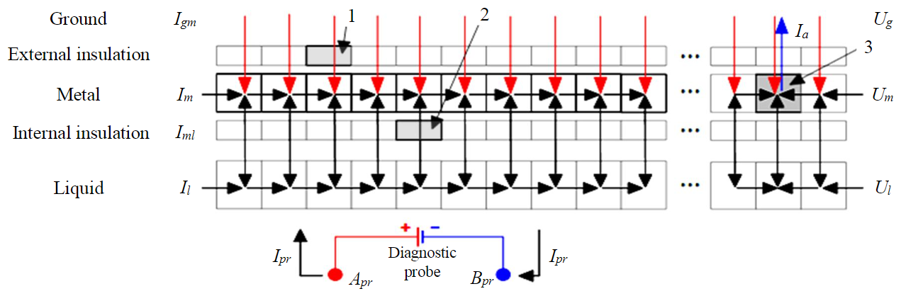
Fig.2. Fragment of a discrete pipeline model 1-2 – sections with broken insulation: 1 – external; 2 – internal; 3 – section with drain point Bt of protective current Ia
Each pipe segment forms fictitious point sources and (or) sinks of current. For each fictitious source and (or) sink, the outgoing and (or) incoming currents are described by Kirchhoff's laws:
where – coordinates of the middle point in the metal of the i-th segment; Apr and Bpr current positions of electrodes of the diagnostic probe inside the transported liquid in the pipe, referred to the middle points of the segments in the liquid.
In equations (8) and (9) condition (4) of no current flow on end faces for pipe metal and transported liquid are considered.
Equations describe the discrete formulas of Ohm's law for the currents between pairs of neighboring segments:
where Sl – is the cross-sectional area of the transported liquid.
The discrete analogue of the formulas for boundary conditions of the third kind at the “ground – metal” and “metal – liquid” boundary is described by equations:
The electric current potential at any point of the homogeneous half-space containing the pipeline, according to the principle of superposition of fields, will be generated by the point anode source of the CPS А and fictitious sources by the number of the formed pipeline segments. The potential is described by equation:
where G(P, Q) – is Green's function [30] of the enclosing homogeneous half-space, a function that calculates the value of electric current field potential at the point P(xP, yP, zP) of the half-space when the point source of electric current of unit intensity is found at the point Q(xQ, yQ, zQ).
The discrete model (8)-(14) by substituting in (14) the ground points located near the ground-metal boundary, is a SLAE with the following unknowns: Um, Ug, Ul, Igm, Im, Il, Iml. Here, each unknown is a vector of segment-averaged current or voltage values. The expanded SLAE matrix is of size (7Mt – 2)´(7Mt – 1). The solution of the SLAE gives the values of the desired current and voltage parameters for each discrete segment. Thus, the original differential mathematical model (1)-(7), describing the distribution of the DC field potential in the system is reduced to a SLAE equations (8)-(14) by the fictitious source method.
The computational experiment is based on the following methodology. The first step is to determine the probe electric field in the transported liquid when the internal and external insulation are undisturbed and the CPS current is zero Ia = 0 А. Call the resulting field the “normal” probe field.
At the second the “working” electric field was calculated – the probe field when the transient resistance of the internal and (or) external insulation on the pipe segment is broken and the CPS current is switched on. The “normal” field was then subtracted from the “working” field. The result of the step is the “abnormal” electric current field.
At steps 1 and 2, the movement of an in-line probe in the pipe was simulated. The size of the in-tube probe was set equal to the length of seven segments of the discrete pipeline model (7 m for the computational experiment below). Fifteen consecutive probe positions were calculated at which the middle of the probe was offset from the middle of the “defective” segment in the range of [–7; +7] segments.
At the third step, the field gradient between the fixed inner points of the probe, which simulates the position of its sensors, was calculated. The initial data of the computational experiment are given in the Table.
Computational experiment initial data
|
Parameter |
Designation |
Value |
|
MP length, m |
Lt |
10000 |
|
Number of segments, psc |
Mt |
10000 |
|
Length of one model segment, m |
l |
1 |
|
MP depth, m |
Ht |
2.0 |
|
MP diameter, m |
Dt |
0.53 |
|
MP wall thickness, m |
htm |
0.008 |
|
Coordinates of point anode A, m |
(xA, yA, zA) |
(5000; 350; 25) |
|
Drainage point coordinates Bt, m |
(xBt, yBt, zBt) |
(5000; 5.0; 2.265) |
|
Drainage point segment number Bt |
– |
5001 |
|
Segment number with an external insulation defect |
– |
2501 |
|
Segment number with an internal insulation defect |
– |
2501 |
|
CPS DC current, A |
Ia |
1.0 |
|
Diagnostic probe, DC current, A |
Ipr |
1.0 |
|
MP metal specific conductivity, S/m |
sm |
4.082∙106 |
|
Ground specific electrical conductivity, S/m |
sg |
0.01 |
|
Liquid specific conductivity, S/m |
sl |
1.04 |
|
MP external insulation transient resistance, Ohm∙m2 |
Cgt |
14000 |
|
MP internal insulation transient resistance, Ohm∙m2 |
Cml |
10000 |
|
MP external insulation transient resistance of defective segment N 2501, Ohm∙m2 |
Cgt_2501 |
1.4 |
|
MP internal insulation transient resistance of defective segment N 2501, Ohm∙m2 |
Cml_2501 |
1.0 |
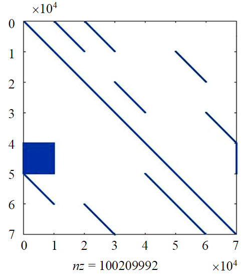
Fig.3. Structure of the extended SLAE matrix
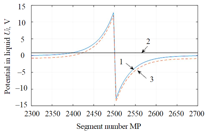
Fig.4. Potential distribution of electric current fields in the conveyed liquid at the zero probe position 1 – “normal”; 2 – “abnormal”; 3 – “working” field
The computational experiment was performed in the Matlab environment using the sparse matrix plug-in. To solve the SLAE left division operations were applied to the matrices. Figure 3 shows the structure of the expanded SLAE matrix for one of the probe positions in the pipe, where the blue dots represent the positions of non-zero elements of the system, with nz denoting the number of non-zero elements of the expanded matrix. The fill density of the expanded matrix is about 2 %.
A complete SLAE matrix for the number of segments Mt = 10000 in double data format has a size of about 36 GB. The problem was solved on a computer with a 10th generation Intel I5 processor and 12 GB of RAM in Matlab using the sparse matrix apparatus. The calculation of the SLAE for one probe position takes about 10-11 h.
The potential distribution of the “normal” probe field (Fig.4, curve 1) the superposition of the CPS fields aperture + probe fields for a “defective” insulated pipe (Fig.4, curve 2) and the “abnormal” (difference between the “working” and “normal” fields, Fig.4, line 3) in the transported liquid. Here, the segment including the segment with defective insulation (N 2501) is taken along the Ox-axis. An insulation failure on the pipe segment results in redistribution of the probe's electric field due to leakage of part of the probe's current into the pipe metal.
For this case, the probe position in the pipe is fixed – the middle of the probe falls in the middle of the “defective” segment (zero probe position dz = 0). Figure 5 shows fragments of the “abnormal” field calculated at some offsets of the in-line probe. The range of probe center segment displacements is in the range of [–7; +7] pipe segments relative to the segment with defective insulation.
It is of practical interest to determine the number of the segment with defective insulation when the diagnostic probe moves inside the MP. The specific potential value in this case is secondary to the nature of the field change during the passage of the defective segment. Therefore, at the third step of the computational experiment, the field gradient between two segments of the diagnostic probe (two measuring probes) that are symmetrical with respect to the center was calculated. Figure 6 shows the “abnormal” field gradients based on the potential differences between the symmetrical probe segments, as the probe moves inside the pipeline. In the figure, the letters zх denote the probe segments used to find the finite differences (х – is the segment displacement relative to the middle segment z0. As can be seen in the figure, the gradient diagrams are symmetric with respect to the “defective” segment, and when the center of the probe coincides with the defective segment, they turn to zero. These gradient properties can be used as an indication of a defective pipe segment detection.
Discussion of results
The DC field potential distribution model of an in-line cathodically polarized pipe probe proposed in this work allows detecting a breach of the internal insulation layer. The inclusion of a diagnostic probe in the model solves two problems. Firstly, the currents flowing inside the transported liquid and flowing from the liquid into the pipe metal can be increased by varying the probe current to values detectable by the instruments. Secondly, the simultaneous tracking of diagnostic probe position in MP and recording of potentials in liquid allow localizing the location of in-line insulation failure with an accuracy determined by the characteristics of the sensor for measuring current potentials (current gradient) in the liquid and the sensor for determining position sensor in the pipe. Locating the probe in a branched pipeline network [34, 35] is one of the important independent subtasks. The determination of the coordinates of a segment with disturbed insulation allows including the electric probing method into the intelligent analytical core of automated control systems for electrochemical protection of MP.
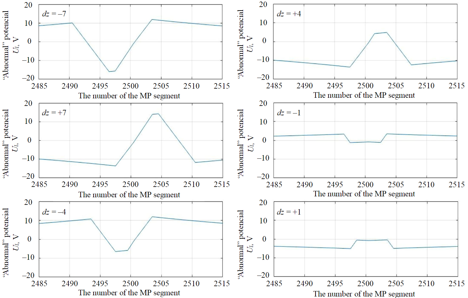
Fig.5. Plots of “abnormal” potential Ul in the transported liquid
The inclusion of an in-line DC source in the model potentially expands the class of pipelines under investigation. This may also include pipelines operated without the use of cathodic protection systems.
The model proposed in the paper in the form of a SLAE (8)-(14) and the method of its solution make it possible to achieve discretization of a pipeline length of 1 m. This is by an order of magnitude greater than the discretization parameters achieved in the previous work of the authors [30] and the studies of other teams in this direction [33, 36].
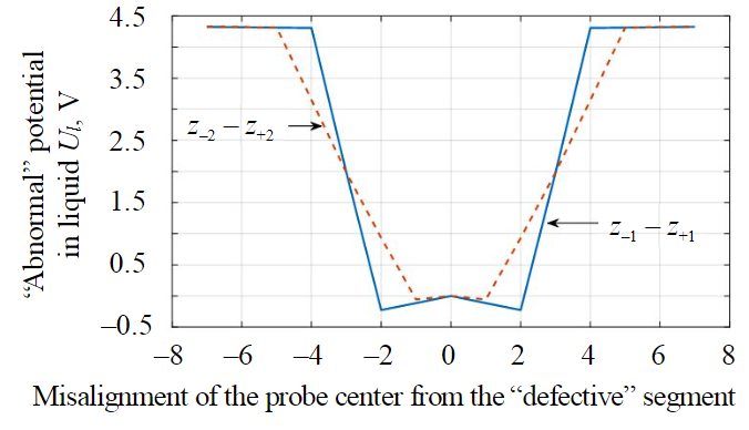
Fig.6. Field gradient distribution in the liquid as the probe moves
Conclusion
The mathematical model proposed in this work describes the distribution of DC field potential in the electrochemical protection system of a MP. The results obtained as a result of modeling for a number of particular cases agree with those previously known [17, 30, 36].
The distinctive features of the model are: taking into account the influence of the electric conductivity of transported liquid and the transient resistance of internal insulating coating on the distribution of electric fields; using the electric field of an in-tube diagnostic probe for quality control of internal insulation. Practical significance consists in the development of modeling methods for systems of electrochemical protection of MP against corrosion and the development of special mathematical and algorithmic support for subsystems of monitoring and control of CPS of MP. The length of one pipeline segment in the model is 1 m, which is an order of magnitude higher than the known solutions. Such an accuracy in coating defect localization makes it expedient to use autonomous robotic complexes for inspection of pipelines.
References
- Nishkevich Yu.A., Kozlov I.A. Corrosion: methods of corrosion control in the oil industry. Moscow: NITs INFRA-M, 2018, p. 88 (in Russian). DOI: 10.12737/monography_59a018d0867c99.11635048
- Mustafin F.M., Chen' Tsyun', Mustafin O.F. et al. Passive protection of pipelines from corrosion. Neftegaz.RU. 2020. N 2, p. 86-90 (in Russian).
- Burkov P.V., Burkov V.P., Fat'yanov D.S., Timofeev V.Yu. Studying the stress-strain state of oilfield pipelines exposed to rill corrosion. Vestnik of Kuzbass State Technical University. 2018. N 3, p. 5-12 (in Russian). DOI: 10.26730/1999-4125-2018-3-5-12
- Ismaiylov G.G., Iskenderov E.Kh., Ismaiylova F.B. Problems of hydrodynamic corrosion in multiphase pipelines. Fizikokhimiya poverkhnosti i zashchita materialov. 2021. Vol. 57. N 1, p. 106-112 (in Russian). DOI: 10.31857/S0044185621010125
- Bolobov V.I., Popov G.G. Methodology for testing pipeline steels for resistance to grooving corrosion. Journal of Mining Institute. 2021. Vol. 252, p. 854-860. DOI: 10.31897/PMI.2021.6.7
- Aginei R.V., Isupova E.V., Guskov S.S., Musonov V.V. Theoretical estimation of the corrosion rate of main pipelines caused by the influence of a geomagnetic-induced stray current source. Nauka i tekhnika v gazovoi promyshlennosti. 2020. N 4, p. 62-73 (in Russian).
- Baktizin R.N., Zaripov R.M., Korobkov G.E., Masalimov R.B. Assessment of internal pressure effect, causing additional bending of the pipeline. Journal of Mining Institute. 2020. Vol. 242, p. 160-168. DOI: 10.31897/PMI.2020.2.160
- Shammazov I.A., Sidorkin D.I., Dzhemilev E.R. Research of the Dependence of the Pipeline Ends Displacement Value When Cutting Out Its Defective Section on the Elastic Stresses in the Pipe Body. IOP Conference Series: Earth and Environmental Science. 2022. Vol. 988. Iss. 2. N 022077. DOI: 10.1088/1755-1315/988/2/022077
- Litvinenko V.S., Dvoynikov M.V., Trushko V.L. Elaboration of a conceptual solution for the development of the Arctic shelf from seasonally flooded coastal areas. International Journal of Mining Science and Technology. 2022. Vol. 32. Iss. 1, p. 113-119. DOI: 10.1016/j.ijmst.2021.09.010
- Manko P.O., Kochergin A.V. Diagnostics of pipelines using in-tube defectoscopes. Vestnik Lugansk Vladimir Dahl National University. 2021. N 9 (51), p. 35-39 (in Russian).
- Movchan I.B., Yakovleva A.A. Approach to automation of field diagnosis data interpretation for localization of pitting in the pipeline wall. International Journal of Civil Engineering and Technology. 2019. Vol. 10. N 2, p. 1571-1581.
- Glinkin D.Y., Mezhuev A.V., Yudin M.I. Promising areas for developing ultrasonic inline inspection tools. Science & Technologies: Oil and Oil Products Pipeline Transportation. 2019. Vol. 9. N 4, p. 434-439 (in Russian). DOI: 10.28999/2541-9595-2019-9-4-434-439
- Bazylev D.N., Romanovich V.A., Vedyakov A.A. Automated method of in-tube ultrasonic control using phased antenna array. Journal of Instrument Engineering. 2019. Vol. 62. N 9, p. 805-813 (in Russian). DOI: 10.17586/0021-3454-2019-62-9-805-813
- Zhukov A.D., Grigoriev M.V., Danilov V.N. The research for an identification of crack – like corrosion – mechanical defect by acoustic in-line inspection tools. Testing. Diagnostics. 2020. N 2, p. 56-63 (in Russian). DOI: 10.14489/td.2020.02.pp.056-063
- Potapov A.I., Kondratev A.V. Non-destructive testing of multilayer medium by the method of velocity of elastic waves hodograph. Journal of Mining Institute. 2020. Vol. 243, p. 348-356. DOI: 10.31897/PMI.2020.3.348
- Mitolo M., Pettinger A. Interactions Between Cathodically Protected Pipelines and Grounding Systems. IEEE Transactions on Industry Applications. 2016. Vol. 52. Iss. 5, p. 3694-3698. DOI: 10.1109/tia.2016.2582795
- Bolotnov A.M., Khisametdinov F.Z. Determining the state of pipe insulation protection according to the results of measurements of “soil-pipe” potential difference. Bulletin of Bashkir University. 2017. Vol. 22. N 1, p. 20-24 (in Russian).
- Dzhala R., Verbenets B., Dzhala V. et al. Contactless testing of insulation damages distribution of the underground pipelines. Procedia Structural Integrity. 2022. Vol. 36, p. 17-23. DOI: 10.1016/j.prostr.2021.12.077
- Bhadran V., Shukla A., Karki H. Non-contact flaw detection and condition monitoring of subsurface metallic pipelines using magnetometric method. Materials Today: Proceedings. 2020. Vol. 28. Part 2, p. 860-864. DOI: 10.1016/j.matpr.2019.12.313
- Bobrov A., Kuten M. Intellectual Innovations in Acoustic Emission Control in the Safety System of Pipeline Transport. Transportation Research Procedia. 2021. Vol. 54, p. 340-345. DOI: 10.1016/j.trpro.2021.02.081
- Asadzadeh S., de Oliveira W.J., de Souza Filho C.R. UAV-based remote sensing for the petroleum industry and environmental monitoring: State-of-the-art and perspectives. Journal of Petroleum Science and Engineering. 2022. Vol. 208. Part D. N 109633. DOI: 10.1016/j.petrol.2021.109633
- Makhutov N.A., Neganov D.A., Studenov E.P., Zorin N.E. Development of status, strength and operating life diagnostics and monitoring methods for continuously operating oil trunk pipelines. Procedia Structural Integrity. 2022. Vol. 40, p. 283-295. DOI: 10.1016/j.prostr.2022.04.038
- Grigorev G.S., Salishchev M.V., Senchina N.P. On the applicability of electromagnetic monitoring of hydraulic fracturing. Journal of Mining Institute. 2021. Vol. 250, p. 492-500. DOI: 10.31897/PMI.2021.4.2
- Golubev I.A., Golubev A.V., Laptev А.B. Practice of using the magnetic treatment devices to intensify the processes of primary oil treating. Journal of Mining Institute. 2020. Vol. 245, p. 554-560. DOI: 10.31897/PMI.2020.5.7
- Mayet A.M., Alizadeh S.M., Nurgalieva K.S. et al. Extraction of Time-Domain Characteristics and Selection of Effective Features Using Correlation Analysis to Increase the Accuracy of Petroleum Fluid Monitoring Systems. Energies. 2022. Vol. 15. Iss. 6. N 1986. DOI: 10.3390/en15061986
- Samimi A., Zarinabadi S., Shahbazi Kootenaei A.H. et al. Corrosion classification of pipelines in hydrocracking units (ISOMAX) by data mining. South African Journal of Chemical Engineering. 2020. Vol. 3, p. 44-50. DOI: 10.1016/j.sajce.2019.11.006
- Shafeek H., Soltan H.A., Abdel-Aziz M.H. Corrosion monitoring in pipelines with a computerized system. Alexandria Engineering Journal. 2021. Vol. 60. Iss. 6, p. 5771-5778. DOI: 10.1016/j.aej.2021.04.006
- Syromyatnikova A., Bolshakov A., Ivanov A. et al. The corrosion damage mechanisms of the gas pipelines in the Republic of Sakha (Yakutia). Procedia Structural Integrity. 2019. Vol. 20, p. 259-264. DOI: 10.1016/j.prostr.2019.12.149
- Lozovan V., Dzhala R., Skrynkovskyy R., Yuzevych V. Detection of specific features in the functioning of a system for the anti-corrosion protection of underground pipelines at oil and gas enterprises using neural networks. Eastern-European Journal of Enterprise Technologies. 2019. Vol. 1. Iss. 5 (97), p. 20-27. DOI: 10.15587/1729-4061.2019.154999
- Krizsky V.N., Alexandrov P.N., Kovalskii A.A., Victorov S.V. Determination Transition Resistance of Cathode-Polarized Main Pipeline on Magnetometery Data. International Journal of Mathematical, Engineering and Management Sciences. 2021. Vol. 6. N 6, p. 1729-1740. DOI: 10.33889/ijmems.2021.6.6.102
- Al-Gabalawy M.A., Mostafa M.A., Hamza A.S., Hussien S.A. Modeling of the KOH-Polarization cells for mitigating the induced AC voltage in the metallic pipelines. Heliyon. 2020. Vol. 6. Iss. 3. N e03417. DOI: 10.1016/j.heliyon.2020.e03417
- Dzhala R., Dzhala V., Savula R. et al. Determination of components of transient resistance of underground pipeline. Procedia Structural Integrity. 2019. Vol. 16, p. 218-222. DOI: 10.1016/j.prostr.2019.07.044
- Khisametdinov F.Z. Parameters of the electric field in cathodic protection of underground pipeline calculation and visualization. Modern high technologies. 2018. N 9, p. 126-130 (in Russian).
- Lutonin A.S., Bogdanova K.A. Development of robotic platform for underground geomonitoring. Izvestiya Tula State University. Technical sciences. 2021. Iss. 12, p. 209-216 (in Russian). DOI: 10.24412/2071-6168-2021-12-209-217
- Bogdanova K.A. Application of SLAM algorithms for three-dimensional modelling of mine workings. Izvestiya Tula State University. Technical sciences. 2021. Iss. 2, p. 134-140 (in Russian).
- Zentsov V.N., Bolotnov A.M., Udalova E.A. et al. Optimization of parameters of electric field of gas product and oil pipes cathodic protection. Bulletin of the Tomsk Polytechnic University. Geo Аssets Engineering. 2019. Vol. 330. N 5, p. 35-43 (in Russian). DOI: 10.18799/24131830/2019/5/255