
Parameter determination of the method of directional unloading of the reservoir based on physical modelling on a true triaxial loading setup
- 1 — Ph.D., Dr.Sci. Deputy Director Institute for Problems in Mechanics, RAS ▪ Orcid
- 2 — Ph.D., Dr.Sci. Head of Laboratory Institute for Problems in Mechanics, RAS ▪ Orcid
- 3 — Ph.D. Junior Researcher Institute for Problems in Mechanics, RAS ▪ Orcid
- 4 — Junior Researcher Institute for Problems in Mechanics, RAS ▪ Orcid

Abstract
The article presents a theoretical and experimental substantiation of the method of directional unloading of the reservoir in fields with low-permeability reservoirs. The relevance of the article is due to the reduction of hydrocarbon resources in modern conditions and the need to create new efficient environmentally friendly technologies to develop hydrocarbon deposits with hard-to-recover reserves, primarily with low-permeability reservoirs. The results of a theoretical study of the stress-strain state in the vicinity of a well, both cased and open, are presented. They are necessary to develop programs for laboratory testing of core specimens from the studied fields. A technique for physical modelling of deformation processes in the bottomhole zone with a decrease in pressure at the well bottom in a true triaxial loading unit is described in order to determine the parameters of the process impact on the formation reservoir, leading to an increase in well productivity. The method was applied to the conditions of the low-permeability reservoir at the Verkhneviluchanskoye oil and gas condensate field in the southwest of the Republic of Sakha (Yakutia). Expe-rimental studies were carried out on a unique scientific unit for true triaxial loading, created at the IPMech RAS, the Triaxial Independent Loading Test System. The directional unloading method was adapted for the studied field, the process parameters of successful application of the method were determined: the bottomhole design, the drawdown values necessary to increase the permeability of the bottomhole formation zone.
None
Introduction
In the context of reducing hydrocarbon resources, when large and accessible deposits are mostly depleted, there is a need to extract hard-to-recover reserves, primarily from low-permeability reservoirs [1, 2]. In this regard, the development and adaptation to the conditions of specific deposits of new and efficient technologies is becoming increasingly important [3]. Among such technologies are multi-stage hydraulic fracturing [4, 5], wave action [6, 7], and method of directional unloading of a formation [8, 9]. Today, both domestic [10] and foreign teams [11, 12] are engaged in improving the scientific foundations of the multi-stage hydraulic fracturing. Main areas of research are numerical simulation of fracture propagation [12], creation of models for studying the evolution of hydraulic fracturing parameters and calculating well productivity considering changes in various process factors [11, 13], experimental study of fracture development in the reservoir [14, 15]. Particular attention is paid to the search for new methodological foundations for assessing and accounting for the parameters of low-permeability formations [16], improving approaches to planning hydraulic fracturing activities [17, 18] and methods for monitoring the use of hydraulic fracturing [19]. When studying the wave action on the formation, the influence of the amplitude and frequency of oscillations on the characteristics of the formation [20, 21] and fluids [22], oil pressure gradient, capillary interfacial tension [23], etc. are considered. The use of wave methods is often considered in combination with other formation stimulation methods [24, 25]. There are also alternative environmentally friendly methods of stimulation, for example, influencing the formation with an electric field [26, 27], the use of polymer flooding [28], injection of carbon dioxide [29, 30], plasma-pulse impact on the reservoir [31].
Methodology
Over the past 30 years, the Institute for Problems in Mechanics of the RAS has been conducting active scientific research in the field of creating innovative technologies for the extraction of hydrocarbon raw materials. A geomechanical approach to the development of fields with low-permeability reservoirs is being advanced. It consists in increasing the permeability of a pay by controlling the stress state of the formation due to its directional unloading from rock pressure. The stress state in the formation in the vicinity of the well is influenced by two factors, the pressure in the well and the geometry of the bottomhole (presence of casing and slots, density and type of perforation). These studies resulted in the creation of a new way to increase the productivity of oil and gas wells, the method of directional unloading reservoir (DUR).
The DUR method was successfully tested at a number of oil fields in Western Siberia and the Perm Krai [32]. When implementing the DUR method, first of all, it is necessary to determine the stresses that must be created in the rock for its fracturing and destruction, and to answer the question of what process operations are necessary for this purpose. For different reservoir rocks, conditions of their occurrence, formation pressures, these conditions are different [33]. Therefore, in order to adapt the DUR method to the conditions of a particular field, a series of tests of rock specimens from this field is carried out according to special loading programs on the Triaxial Independent Loading Test System (TILTS) [34], which makes it possible to recreate the stress and strain states that actually occur in the formations of oil and gas fields in cubic rock specimens. The experiments result in a conclusion about the most effective conditions to implement the DUR method at this field, and the expected effect is assessed.
The use of the DUR method in fields with low-permeability reservoirs, due to their increased strength, may require the preliminary introduction of stress concentrators into the formation, perforation of a certain type and density, which is necessary to initiate the fracturing process in the reservoir, as well as its intensification. This is necessary even in open-hole wells, for which the application of the DUR technology is most effective.
The TILTS is a unique experimental stand for studying the deformation and filtration properties of rocks. Its distinguishing feature is the possibility of creating true triaxial stress states in cubic rock specimens. In addition, such a unit makes it possible to study the effect of stresses arising in rocks on their filtration properties.
Before carrying out experiments, it is necessary to draw up programs for loading specimens at the TILTS, corresponding to the stresses that actually arise in the formation during well operation. For this purpose, mathematical calculations, both analytical and numerical, are carried out. On their basis, programs for loading specimens are compiled. Then each of these programs is implemented at the TILTS. When testing, it is established for each of the programs, in which part of it, respectively, at what drawdown value, inelastic deformation of the rock occurs with its fracturing or loosening, accompanied by an increase in permeability. Thus, the preparation of loading programs for specimens is an important task.
The following are calculations to determine the stresses acting in the vicinity of perforations in cased and open wells. The stress state in the vicinity of the perforation hole is determined by the external stress (away from the well or perforation hole), the fluid pressure inside the well and the perforation hole for an open well, and the back pressure on the rock from the cement and the fluid pressure inside the perforation hole for a cased well.
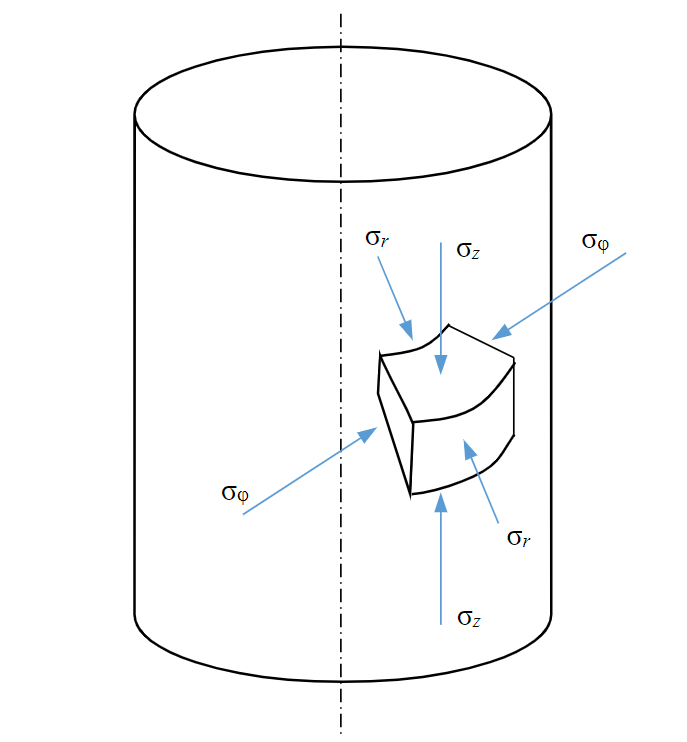
Fig.1. Stresses in the vicinity of the well
Stresses in the vicinity of an open-hole vertical well
The external stress for the well is the stress from the rock pressure in the depth of the formation q (Fig.1).
In the case of uniform all-round compression, the stresses around an open well in the coordinate system r, z, φ, associated with the well, according to the solution of the Lame problem [35], are equal to:
where pw is the pressure in the well; R is the well radius; r is the distance from the well axis to the considered point; pw > 0, q < 0 (hereinafter, the compressive stresses are considered negative). The effective stresses with which the soil skeleton is loaded:
Thus, when the pressure in the well decreases, i.e., with increasing drawdown, the stress components sφ and sz in the bottomhole formation zone (BFZ) increase in absolute value, and the radial stress sr decreases.
The effective stresses on the wall (r = R) of an open well, considering the fact that p(r) = pw on it, from (2) are equal to:
Stresses in the vicinity of a cased vertical well
Back pressure pc acts on the well wall from the side of the cement, pc > 0. Effective stresses in the vicinity of the well:
Assuming that on the boundary of a cased well, after the cement slurry has hardened, the pressure is completely restored to the value of the rock pressure, i.e., pc = |q|, from formulas (4) we have
where p0 is formation pressure.
Thus, a change in pressure in a cased well without perforations does not affect the stress state in its vicinity.
Stresses on the perforation hole surface in an open well
The external stress for the perforation hole is not the stress from the rock pressure in the depth of the formation, but the stress (1) acting around the open hole of well (Fig.2).
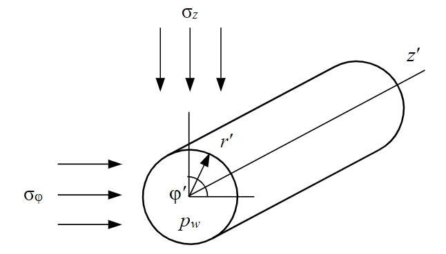
Fig.2. Stresses in the vicinity of a perforation in an open well
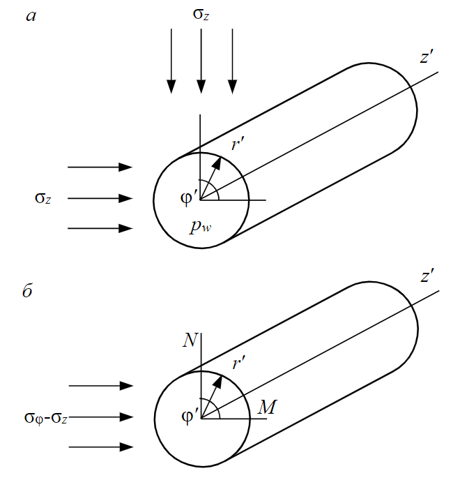
Fig.3. Stresses in the vicinity of a perforation for Lame problem 1 (a) and Kirsch problem 2 (b)
Stresses in the vicinity of a perforation hole are determined by the superposition of solutions to the Lame problem [34] and a problem similar to the Kirsch problem [36] (Fig.3).
In the coordinate system r′, z′, φ′ on the perforation hole wall, i.e., at r′ = Rh, where Rh is the perforation hole radius (Fig.3, a), to change the stresses depending on the distance from the well axis, we have
At the top point N of the vertical section of the perforation hole (Fig.3, b), for changing stresses depending on the distance from the well axis, we have
The sum of components (6) and (7) with the superposition of stress fields at point N:
Subject to (1)
Then the effective stresses on the perforation hole wall, given that p(r) = pw on it, are equal to:
It can be seen from expressions (10) that the stresses along the perforation hole wall vary depending on the distance from the well wall.
For r = R
For r = 2R
For r = 3R
Stresses on the perforation hole wall in a cased well
As follows from formula (5), the perforation hole in the cased well is under the action of external stress that occurs in the vicinity of the cased well and coincides with the natural stress from rock pressure in the depth of the formation. Therefore, the stresses in its vicinity are given by formula similar to the expressions for an open well (1) and (2), in which the well radius must be replaced by the perforation hole radius, and the distance from the well axis, by the distance from the perforation hole axis. We have:
for effective stresses
Thus, in a cased well, the stresses along the perforation hole wall are constant and equal (assuming in (15) r′ = Rh,p(r')=pw):
It can be seen from (1), (2) and (14), (15) that the stress distribution in the vicinity of the perforation hole in a cased well, depending on the relative distance from the centre of the perforation hole, coincides with the stress distribution in the vicinity of an open well depending on the relative distance from its centre.
From expressions (11)-(13) and (16) it follows that the concentration of the maximum compressive effective stress α = Sφ′/q on a part of the perforation hole wall for an open well is much higher than for a cased one. If at complete drainage of the well (pw = 0) on the entire perforation hole wall in a cased well, α = 2, then on the entire perforation hole wall in an open well, the value of α exceeds 2. On the well wall at r = R, the concentration is maximum (α = 5) and gradually decreases with distance from the well: at r = 2R a = 2.75, at r = 3R α = 2.33, etc.
Specimen testing programs
For testing at the TILTS, cubic rock specimens were made from a low-permeability reservoir of the Verkhneviluchanskoye oil and gas condensate field with a permeability in the range of 0.01-49.4∙10–3 µm2. The Yuryakhsky pay of the field is stratigraphically confined to carbonate deposits, composed of dolomites and dolomitic limestones. Formation pressure is close to hydrostatic 17.5 MPa. The core material for testing was taken from a depth of about h = 1750 m, where the absolute value of rock pressure |q| = γh with an average density of overburden of γ = 2.3 g/cm3 is 40.25 MPa.
During the tests, the specimens were loaded according to programs that corresponded to the stresses arising in the vicinity of the well for three bottom hole designs: open hole, perforation in a cased well, perforation in an open well.
Stresses on an open well boundary
The corresponding loading program for the specimens is shown in Fig.4, a and is built on the basis of formulas (2), in which r = Rc is assumed. The y-axis plots the stresses s1, s2, s3 applied in the TILTS to the specimens along three axes. For an open well, they correspond to the absolute values of the stresses sz, sφ, sr acting in the vicinity of the well (see Fig.1). Point A in Fig.4, a corresponds to the stresses in the soil skeleton before drilling the well; point B – the state when the well is drilled and the pressure in it is equal to the formation pressure; points on the segment BC – a decrease in pressure at the well bottom (point C – complete “drainage” of
the well).
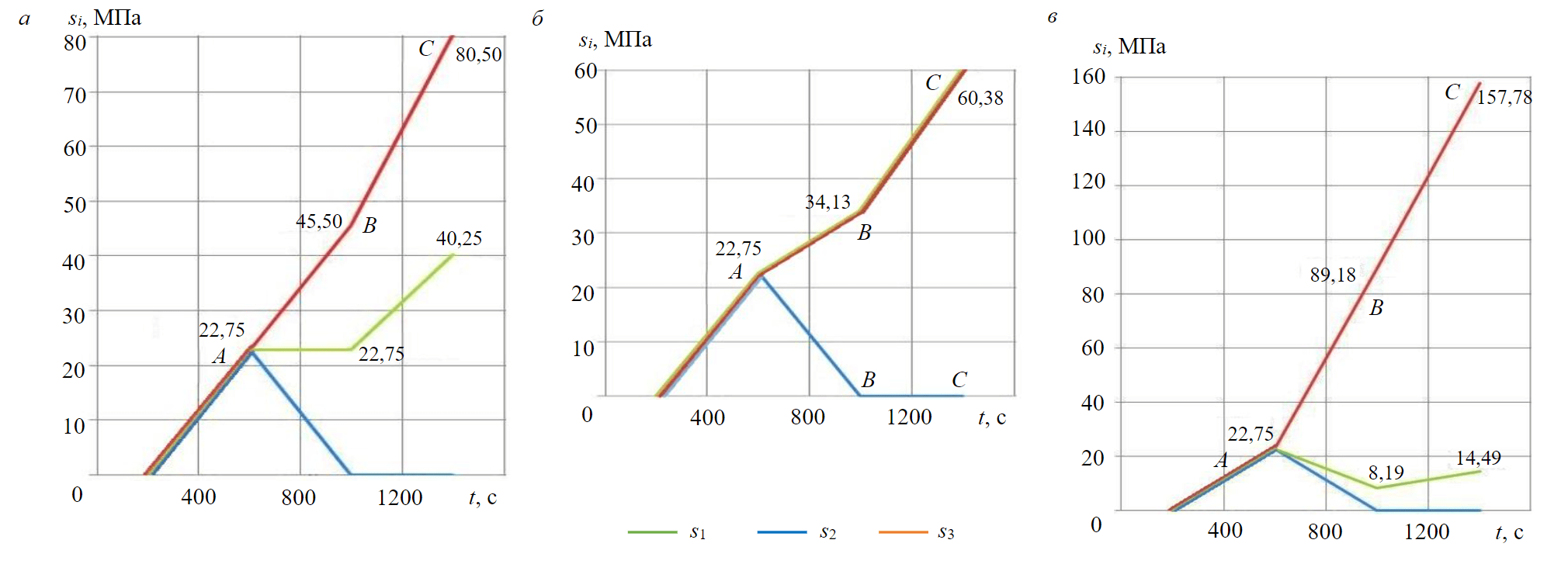
Fig.4. Loading program “open well” (a), “perforation in a cased well” (b), “perforation in an open well” (c)
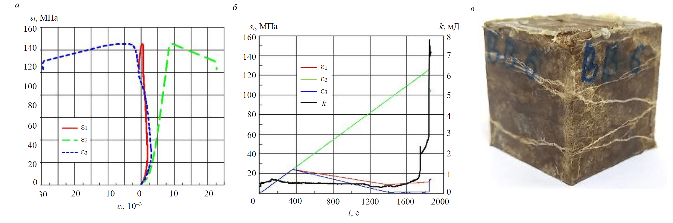
Fig.5. The results of testing the specimen according to the program “perforation in an open well”: a – specimen deformation curves; b – change in the permeability of the specimen during the experiment; c – photograph of the specimen after testing
During the experiment, the components of specimen deformation along three axes and its permeability in the bedding plane are measured.
Stress near a perforation hole in a cased well
If the perforation hole length is large enough, then the stress state that occurs in the vicinity of the walls of the hole is similar to that in the vicinity of an open well. Therefore, the specimen testing programs for these two cases will be the same. However, if the length of the hole is small, then to describe the stresses in its immediate vicinity, one can use the solution of the problem of the stress field in the vicinity of a hollow sphere, which is under the action of internal pressure pw and loaded far away with an all-around compressive load q [36].
In this case, a radial stress σr and two circumferential stresses σθ and σφ act near the perforation hole tip. Accordingly, the rock soil skeleton is loaded with effective stresses sr, sθ, sφ.
Figure4, b shows the specimen loading program corresponding to the change in stresses near the perforation hole tip with a decrease in pressure pw at the bottom of the well; s1, s2, s3 are the stresses applied along axes 1, 2, 3 to the specimen in the TILTS. They correspond to the absolute values of stresses sφ, sθ, sr acting at the perforation hole tip sr = 0, sθ = sφ = 3/2(q + pw) [36].
Stress near a perforation in an open well
It is shown that stresses along the perforation surface in an open well vary depending on the distance from the well axis according to expressions (8)-(10). They are maximum near the well wall and minimum near the hole tip. The experiment simulated the change in stress at a point on the perforation surface, at a distance of r = 1.25R from the well axis.
Figure 4, c shows the program for specimen testing, built on the basis of formulas (10). The stresses s1, s2, s3 plotted in it correspond to the absolute values of the stresses sz′, sφ′, sz′ acting in the vicinity of the perforation.
Specimen test results
Three specimens from the Verkhneviluchanskoye oil and gas condensate field were tested at the TILTS according to the above programs. When tested according to programs that simulate the change in stresses in the vicinity of an open well (Fig.4, a) and a perforation in a cased well (Fig.4, b), the specimens during the entire experiment were deformed elastically without an increase in permeability up to stresses corresponding to the complete drainage of the well. The initial permeability of the specimens was 11.5 and 1.4 mD.
A different pattern was observed when testing the specimen according to the program “perforation in an open well”, shown in Fig.4, c and simulating the change in stress at a point on the surface of the perforation, spaced from the well axis by
a distance r = 1.25R. Fig.5 shows the deformation curves of the specimen during the experiment and the change in its permeability.
Figure 5, a shows that when modelling the pressure drop in the perforation vicinity in an open well, the specimen was elastically deformed to a stress of s2 = 120 MPa, and then its inelastic deformation began and the specimen was destroyed at s2 = 126 MPa. Since the stress s2 applied to the specimen in the loading block of the TILTS corresponds to the absolute value of the hoop stress |sφ′| in the perforation vicinity, then from expression (10) we have pw = |q| – (25/98)s2. Accordingly, the beginning of inelastic deformation of the specimen corresponds to the pressure at the bottom of the well pw = 9.6 MPa, and the destruction of the specimen corresponds to the pressure pw = 8.1 MPa.
Initial permeability of the specimen k0 was 0.4 mD, and during loading the specimen at the stage of its destruction, it increased to 7.8 mD (Fig.5, b).
Figure 5, c shows a photo of the specimen after testing. It clearly shows the system of fractures formed in the specimen, which led to an increase in its permeability.
Conclusions
1. From the practice of operating gas wells, especially in fields with low-permeabi-lity reservoirs, it is known that a decrease in pressure at the bottom of cased wells with a perforated bottomhole practically until they are drained does not lead to an increase in well production. A similar pattern is often observed for open wells.
It follows from formulas (3) and (16) that when the well is completely drained, i.e., at pw = 0, both on an open hole surface and on a perforation surface in a cased hole, there are maximum compressive hoop stresses equal to 2q. The absence of an increase in well flow rate in this case indicates that the creation of deep drawdowns in wells with such a bottomhole design does not lead to the occurrence of stresses in the formation sufficient to initiate fracturing and destruction of the rock in the bottomhole zone. In other words, it will not be possible to increase the productivity of wells with such a bottomhole design using the DUR method.
In this case, pre-perforation of an open well can help, since as follows from (10)-(13), compressive stresses arise in the vicinity of the perforation, which significantly exceed the stresses in other well bottomhole designs.
This conclusion is confirmed by the results of the experiments presented in the work.
2. From formulas (10)-(13) it follows that a significant stress concentration on the surface of a perforation in an open well occurs no more than at a distance of 2-3 hole radii from its axis. With a well radius of 75 mm, this is 150-225 mm from its axis. Moreover, the zone of rock fracturing and destruction is the larger, the larger the perforation (15).
Therefore, the optimal perforations in an open well for the DUR method implementation should be short enough, but wide. In this case, the effect of using DUR method will be maximum.
3. The geomechanical approach using physical modelling of deformation, destruction, and filtration in pays can serve as the basis for the development of new efficient and environmentally friendly technologies for increasing the productivity of oil and gas wells and increasing oil recovery from formations with hard-to-recover reserves.
References
- Alekseev A.D., Zhukov V.V., Strizhnev K.V., Cherevko S.A. Research of hard-to-recovery and unconventional oil-bearing formations according to the principle “in-situ reservoir fabric”. Journal of Mining Institute. 2017. Vol. 228, p. 695-704. DOI: 10.25515/PMI.2017.6.695
- Yan Song, Zhuo Li, Lin Jiang, Feng Hong. The concept and the accumulation characteristics of unconventional hydrocarbon resource. Petroleum Science. 2015. Vol. 12, p. 563-572. DOI: 10.1007/s12182-015-0060-7
- Povzhik P.P., Serdyukov D.V., Galai M.I., Demyanenko N.A. Increasing oil recovery factor in depleted deposits with low reservoir pressure. Delovoi zhurnal Neftegaz.RU. 2018. N 6 (78), p. 64-68 (in Russian).
- Galeev R.R., Zorin A.M., Kolonskikh A.V. et al. Optimal Waterflood Pattern Selection with Use of Multiple Fractured Horizontal Wells for Development of the Low-Permeability Formations. Oil Industry. 2013. N 10, p. 62-65 (in Russian).
- Govzich A.N., Bilinchuk A.V., Fajzullin I.G. Horizontal Well Multi-Stage Fracturing-Gazprom Neft JSC Experience. Oil Industry. 2012. N 12, p. 59-61 (in Russian).
- Ganiev R.F., Ganiev O.R., Ukrainskii L.E. Resonant macro- and micromechanics of an oil reservoir. Intensification of oil production and enhanced oil recovery. Мoscow: Institut komp'yuternykh issledovanii, 2014, p. 225 (in Russian).
- Ganiev R.F., Ukrainskiy L.E. Nonlinear wave mechanics and technologies. Wave and oscillatory phenomena on the Basis of High Technologies. Danbury: Begell Hause, 2012, p. 527.
- Khristianovich S.A., Kovalenko Yu.F., Kulinich Yu.V., Karev V.I. Increasing the productivity of oil wells using the geo-loosening method. Neft' i gaz Evraziya. 2000. N 2, p. 90-94 (in Russian).
- Karev V., Kovalenko Y., Ustinov K. Directional unloading method is new approach to enhancing oil and gas well productivity. Advances in Oil and Gas Exploration and Production. Switzerland: Springer International Publishing, 2020, p. 155-166. DOI: 10.1007/978-3-030-26608-0_10
- Serdyukov S., Degtyareva N., Patutin A., Shilova T. Open-hole multistage hydraulic fracturing system. Journal of Mining Science. 2016. Vol. 52, p. 1210-1215. DOI: 10.1134/S1062739116061759
- Xu D.J., Liao R.Q., Li Z.W. et al. Research on productivity for multi-stage fracturing of horizontal wells. Chemical Engineering Transactions. 2015. Vol. 46, p. 1189-1194. DOI: 10.3303/CET1546199
- Lecampion B., Desroches J. Simultaneous initiation and growth of multiple radial hydraulic fractures from a horizontal wellbore. Journal of the Mechanics and Physics of Solids. 2015. Vol. 82, p. 235-258. DOI: 10.1016/j.jmps.2015.05.010
- Zhiming Chen, Xinwei Liao, Xiaoliang Zha et al. Performance of multiple fractured horizontal wells with consideration of pressure drop within wellbore. Journal of Petroleum Science and Engineering. 2016. Vol. 146, p. 677-693. DOI: 10.1016/j.petrol.2016.07.009
- Jianguang Wei, Saipeng Huang, Guangwei Hao et al. A multi-perforation staged fracturing experimental study on hydraulic fracture initiation and propagation. Energy Exploration & Exploitation. 2020. Vol. 38. Iss. 6, p. 2466-2484. DOI: 10.1177/0144598720914991
- Jianye Mou, Xuezhi Hui, Lei Wang et al. Experimental Investigation on Tool-Free Multi-Stage Acid Fracturing of Open-Hole Horizontal Wells by Using Diversion Agents. SPE International Hydraulic Fracturing Technology Conference and Exhibition, 16-18 October 2018, Muscat, Oman. OnePetro, 2018. N SPE-191415-18IHFT-MS. DOI: 10.2118/191415-18IHFT-MS
- Galkin S.V., Krivoshchekov S.N., Kozyrev N.D. et al. Accounting of geomechanical layer properties in multi-layer oil field development. Journal of Mining Institute. 2020. Vol. 244, p. 408-417. DOI: 10.31897/PMI.2020.4.3
- Votinov A.S., Seredin V.V., Kolychev I.Y., Galkin S.V. Possibilities of accounting the fracturing of Kashiro-Vereyskian carbonate objects in planning of proppant hydraulic fracturing. Journal of Mining Institute. 2021. Vol. 252, p. 861-871. DOI: 10.31897/PMI.2021.6.8
- Burenina I.V., Avdeeva L.A., Solovjeva I.A. et al. Improving Methodological Approach to Measures Planning for Hydraulic Fracturing in Oil Fields. Journal of Mining Institute. 2019. Vol. 237, p. 344-353. DOI: 10.31897/PMI.2019.3.343
- Grigorev G.S., Salishchev M.V., Senchina N.P. On the applicability of electromagnetic monitoring of hydraulic fracturing. Journal of Mining Institute. 2021. Vol. 250, p. 492-500. DOI: 10.31897/PMI.2021.4.2
- Galimzyanova A.R., Gataullin R.N., Marfin E.A., Fasfiev B.R. The inflow of liquid to a horizontal well with acoustic impact on the formation. Engineering and Mining Geophysics. 2018. Vol. 2018, p. 1-6. DOI: 10.3997/2214-4609.201800531
- Marfin E.A., Kadyirov A.I. Increase in Oil Production under Acoustic Stimulation of the Reservoir. European Association of Geoscientists & Engineers. Conference Proceedings. 2021. Vol. 2021, p. 1-5. DOI: 10.3997/2214-4609.202150014
- Dehshibi R.R., Mohebbi A., Riazi M., Danafar F. Visualization study of the effects of oil type and model geometry on oil recovery under ultrasonic irradiation in a glass micro-model. Fuel. 2019. Vol. 239, p. 709-716. DOI: 10.1016/j.fuel.2018.11.071
- Yongjun Hou, Ran Zhou, Xiaokang Long et al. The design and simulation of new downhole vibration device about acoustic oil recovery technology. Petroleum. 2015. Vol. 1. Iss. 3, p. 257-263. DOI: 10.1016/j.petlm.2015.09.001
- Gataullin R.N., Kadyirov A.I. Intensifying oil extraction by wave action methods on productive layers. SOCAR Proceedings. 2020, p. 78-90 (in Russian). DOI: 10.5510/OGP20200200434
- Hossein Hamidi, Amin Sharifi Haddad, Ephraim Wisdom Otumudia et al. Recent applications of ultrasonic waves in improved oil recovery: A review of techniques and results. Ultrasonics. 2021. Vol. 110. N 106288. DOI:10.1016/j.ultras.2020.106288
- Taheri-Shakib J., Shekarifard A., Naderi H. et al. Characterization of the wax precipitation in Iranian crude oil based on Wax Appearance Temperature (WAT): Part 1. The influence of electromagnetic waves. Journal of Petroleum Science and Engineering. 2018. Vol. 161, p. 530-540. DOI: 10.1016/j.petrol.2017.12.012
- Taheri-Shakib J., Shekarifard A., Naderi H. et al. Experimental investigation of the asphaltene deposition in porous media: Accounting for the microwave and ultrasonic effects. Journal of Petroleum Science and Engineering. 2018. Vol. 163, p. 453-462. DOI: 10.1016/j.petrol.2018.01.017
- Palyanitsina A., Safiullina E., Byazrov R. et al. Environmentally safe technology to increase efficiency of high-viscosity oil production for the objects with advanced water cut. Energies. 2022. Vol. 15. Iss. 3. N 753. DOI: 10.3390/en15030753
- Shanxue Jiang, Yuening Li, Fang Wang et al. A state-of-the-art review of CO2 enhanced oil recovery as a promising technology to achieve carbon neutrality in China. Environ Research. 2022. Vol. 210. N 112986. DOI: 10.1016/j.envres.2022.112986
- Núñez-López V., Gil-Egui R., Hosseini S.A. Environmental and Operational Performance of CO2-EOR as a CCUS Technology: A Cranfield Example with Dynamic LCA Considerations. Energies. 2019. Vol. 12. Iss. 3. N 448. DOI: 10.3390/en12030448
- Molchanov A.A., Ageev P.G. Implementation of new technology is a reliable method of extracting reserves remaining in hydro-carbon deposits. Journal of Mining Institute. 2017. Vol. 227, p. 530-539. DOI: 10.25515/PMI.2017.5.530
- Karev V.I., Kovalenko Yu.F., Ustinov K.B. Modelling of geomechanical processes in the vicinity of oil and gas wells. Moscow: IPMex RAS, 2018, p. 472 (in Russian).
- Darvishpour A., Seifabad M.C., Wood D.A., Ghorbani H. Wellbore stability analysis to determine the safe mud weight window for sandstone layers. Petroleum Exploration and Development. 2019. Vol. 46. Iss. 5, p. 1031-1038. DOI: 10.1016/S1876-3804(19)60260-0
- Karev V.I., Kovalenko Yu.F. Triaxial loading system as a tool for solving geotechnical problems of oil and gas production. True Triaxial Testing of Rock. London: CRC Press, 2012, p. 301-310.
- Ljav А. Mathematical theory of elasticity. Мoscow, Leningrad: Obedinennoe nauchno-tekhnicheskoe izdatelstvo NKTP SSSR, 1935, p. 674 (in Russian).
- Timoshenko S.P. Theory of elasticity. Moscow: Nauka, 1979, p. 560 (in Russian).