
Methodology for testing pipeline steels for resistance to grooving corrosion

Abstract
The methodology for testing pipeline steels is suggested on the assumption that for the destruction of pipes in field oil pipelines by the mechanism of grooving corrosion the simultaneous fulfillment of such conditions as the occurrence of scratches on the lower generatrix of the pipe, eventually growing into a channel in the form of a groove, emulsion enrichment with oxygen, presence of pipe wall metal in a stressed state, presence of chlorine-ion in the oil-water emulsion is required. Tests are suggested to be carried out in 3 % aqueous solution of NaCl with continuous aeration by air on bent plates 150×15×3 mm, made of the analyzed steel, the middle part of which is under the action of residual stresses σres, close to the level of maximum equivalent stresses σeqv in the wall of the oil pipeline, with the presence of a cut on this part on the inner side of the plate as an initiator of additional mechanical stresses. Using the value of the modulus of normal elasticity of the analyzed steel, the degree of residual strain of the elastic-plastic body from this material, corresponding to the value σres ≈ σeqv is calculated, based on which the plates are bent to the required deflection angle, after which the cut is applied to them. After keeping the plates in the corrosive medium for each of them the increase in depth of the cut as a result of corrosion of the walls by the corrosive medium is analyzed, from which the rate of steel K by the mechanism of grooving corrosion is calculated taking into account the duration of tests. Corrosion rate values for two pipe steel grades determined by the suggested procedure are given. The comparison of K values obtained leads to the conclusion about the higher resistance to grooving corrosion of 09G2S steel.
None
Introduction
Despite the intensive development of renewable energy sources [1], oil continues to be a major component of the overall global energy balance. Ensuring uninterrupted transport of oil and oil-containing products through trunk and field pipelines is an important scientific and technical challenge. Metal corrosion is the cause of accidents in many industries, including oil and gas industry. It has been estimated that in Russia there are over 80 000 pipeline [2] and reservoir [34] accidents annually, and the majority of them are due to corrosion-related damages [8]. The experience of operating field pipelines shows that the main cause of accidents is corrosion of the inner surface of the lower pipe generatrix, which occurs when pumping oil-water emulsions with heavy mineralized water containing solid abrasive particles through the pipeline [5]. This type of corrosion is referred to as grooving corrosion due to the specific appearance of the fracture site, resembling a stream flowing along the bottom of the pipe (Fig.1).
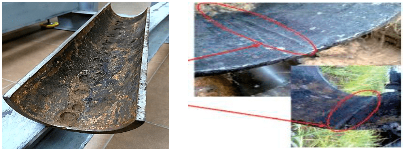
Fig.1. Typical view of a field pipeline affected by grooving corrosion
There are numerous papers on grooving corrosion, e.g. [4, 9, 14], but the mechanism of this process and factors influencing its intensity have not been finally determined. Particularly, it relates to the effect of pipeline stress state on the rate of corrosion damage of the pipe metal and the role of groove in the corrosion process [3, 25]. As the practice of field pipeline operation shows, though there are a number of developed protection methods (installation into the pipeline section of different devices that turbulate the emulsion flow [12], application of inhibitors [14], protective coating of the pipe inner surface [16], use of preliminary water discharge units, etc.) the problem of grooving corrosion in Russia and worldwide is still far from being completely solved. To the greatest extent, it is relevant for long-operating field pipelines, where sections of steel pipes damaged by grooving corrosion have to be periodically replaced with new ones that require replacement after some time.
This paper proposes the technique of corrosion laboratory testing of steels [11] under conditions simulating possible inter-field pipeline wall damage under grooving corrosion, which allows to select compositions that are resistant to grooving corrosion from existing and engineering pipeline steels and to further recommend these compositions for using in field pipelines. Another application of the technique is to study the effect of stressed state and the presence of a cut on the stressed structure, which simulates a trace of grooving corrosion, on the corrosion rate of the metallic structure in the reaction medium. The technique is not designed to determine resistance of pipeline steels in sulphur-containing media [24, 28, 32], as well as under conditions promoting stress-corrosion of steels [25, 30, 33] and stress corrosion cracking [22, 27, 29] due to significant differences in the mechanisms of these processes.
Statement of the problem
When developing the methodology, it was assumed that grooving corrosion of field pipelines occurs when the following basic conditions are simultaneously met:
- separation of the water-oil emulsion with the water fraction washing over the lower generatrix of the pipe;
- presence of dissolved oxygen in the water in contact with the metal at a sufficient concentration to allow the electrochemical corrosion reaction of the pipe metal with anodic control. (This may occur, for example, when oil-water emulsions are produced using formation water enriched with oxygen or when an oil-water emulsion is intensively mixed in contact with air). Only under this condition the level of pipe stress can affect the rate of metal corrosion;
- presence of corrosion active impurities in water of oil-water emulsions, coming from formation water, the most reactive of which is chlorine-ion [13] (influence of anion S2– anion is not taken into account in this methodology), and highly abrasive solid particles;
- effect of tensile stress on the pipe wall, facilitating the release of iron ions from the steel into the aqueous solution during the anodic phase of the process and, consequently, intensifying the corrosion process of the pipe metal;
- appearance of scratches on the lower generatrix of the pipe as a result of abrasion by solids contained in the emulsion, developing over time into a groove, the metal of the walls and bottom of which is subject to additional tensile stresses, maximum in the metal of the bottom part [4, 14, 26].
Methodology
In order to satisfy mentioned conditions, it is proposed to test steels for resistance to grooving corrosion in oxygenated aqueous chloride medium, on the samples subjected to tensile stresses close to the level of equivalent stresses in the pipe, with a grooving cut on them according to the following methodology.
Preparation for the tests
The value of maximum equivalent stresses arising in the pipe wall of the analyzed field pipeline during oil-water emulsion pumping is estimated, taking into account the presence of upward and downward sections on it, which cause bending of the pipeline [10, 23]:
where σ1 – ring stresses caused by internal medium pressure, MPa; σ2 – longitudinal stresses caused by bends in the pipeline, MPa; σ3 – stresses of technological origin remaining in the wall after pipe manufacture, MPa [6, 19].
For the 219×8 mm ascending pipeline section with a bend radius of 219 m, as one of the main ones in the nomenclature of field pipelines, at operating pressure of 4 MPa and temperature of pumped emulsion of 60 °С values σ1 , σ2 , σ3 are 51, 95 and 35 MPa, parameter σeqv has a value ~ 160 MPa, which was used in calculations.
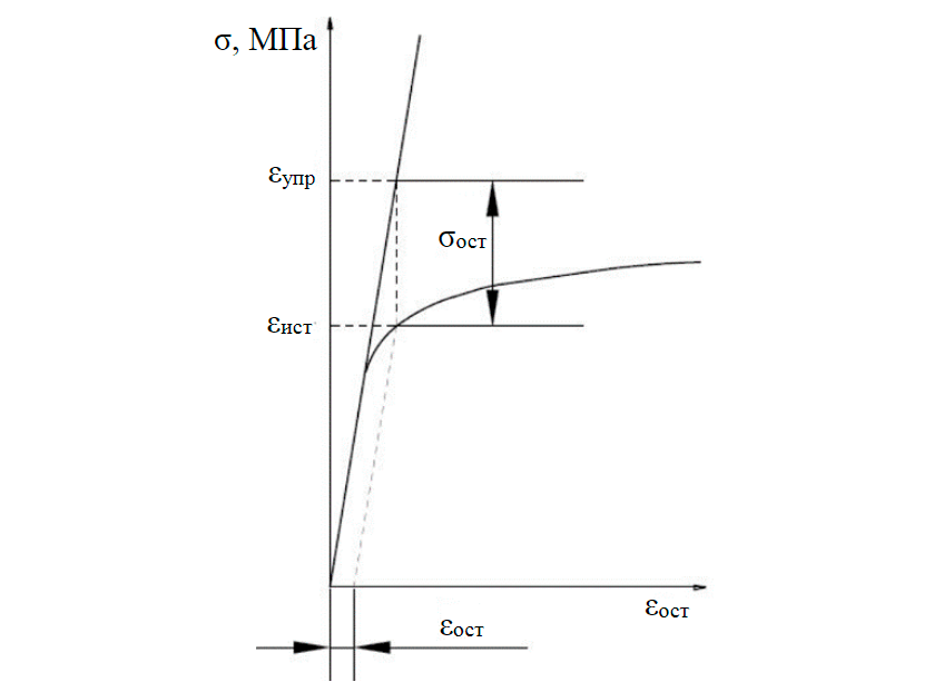
Fig.2. Graphical interpretation of the solution to the problem of finding residual stress in an elastic-plastic body σel – stress that would be created in the body, assuming the ideal elasticity of its material; σact – is the actual stress, corresponding to a given value of the residual strain on the tensile diagram of the material
Plates of 150×15×3 mm in size are cut across the rolling direction (pipe axis) from rolled pipeline steels used for manufacturing welded pipes of field pipeline, or from the pipe body, in the case of pipes obtained by rolling. The plates are bent in clamps up to residual deflection, providing residual stresses σres in the middle, plastically deformed arc-shaped part of plates, close to σeqv in a pipe. Thus, as proved in [35], on the inner side of the plates these are tensile residual stresses, and on the outer side – compression stresses. Provision of equality σres = σeqv is reached by providing the metal in the middle part of the plate necessary degree of residual deformation εres, which according to Genki theorem [18] (Fig.2) for elastic-plastic body corresponds to the value σres:
εres = σres/Е, (1)
where Е – modulus of normal elasticity for the steel analyzed.
Considering that for all pipeline steels the E value does not differ significantly (200 GPa), the required level of residual stresses σres = σeqv = 160 MPa in the elastic-plastic body of these steels, considered in the example, is reached at the degree of residual strain of the metal εres ~ 0.0008 or 0.08 %.
The degree of residual strain εres received by the metal in the middle part of the arc-shaped plates is estimated from the radius of the circumference R, which can be inscribed in this arc-shaped part (Fig.3). The values of εres and R are in relation to each other
where r – distance from the neutral axis to the edge of the plate (half of the thickness), mm.
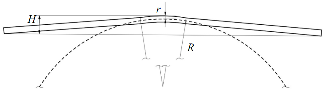
Fig.3. View of a curved plate with the middle part shaped in a circumference of the required radius R, defined using a computer program Autodesk AutoCAD
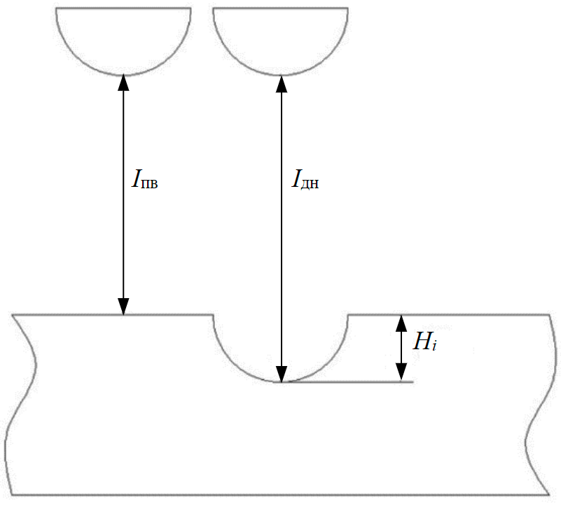
Fig.4. Scheme for determining the depth of cut at a fixed point
In accordance with expression (2) at r = 1.5 mm the required level εres = 0.0008 is achieved by bending the middle part of the plates to the shape of an inscribed circumference with radius R ~ 1.8 m, which for plates of given geometry (150×15 mm) corresponds to the deflection of the plate Н φ 8 mm.
After bending the plates until the radius R has reached the required value, it is assumed that the metal of the middle plastically deformed part is subject to the same residual stresses as the pipe metal of the field pipeline.
Using a 1 mm thick disc shaped cutter with a cutting part in the form of a hemisphere with a radius of 0.5 mm, a crosscut is made in the middle of the plates on the inside with a depth of ~ 0.2 mm and approximately groove-shaped form at the bottom generatrix of the pipeline. Such a cut on a stressed structure serves as a concentrator of additional tensile stresses in the surrounding metal [14, 17, 31] and, as may be concluded, should intensify the corrosion rate. For example, with a cut of 0.2 mm deep on the curved plate of the considered configuration with σres = 160 MPa residual stress equal to 200 MPa occurs in the metal of the bottom of the cut.
Using a LaboMet-1 optical microscope with a focal length scale step M = 0.003 mm, the exact depth of the cut at the fixed points is determined. For this purpose, the cut along its entire length is optically divided into equal sections, e.g. 1 mm in length. The position of the boundary points (n = 13) is fixed and for each of these the difference in focal lengths in divisions from the bottom of the cut to the plate surface near the cut is determined by rotating the fine adjustment drum ΔI = Ibt – Isf with appropriate recalculation of ΔI (using M) to the original cut depth Hi at that point (Fig.4). To prevent a change in the focal distance to the plate surface near the cut as a result of the corrosive environment, this surface is coated with a protective acetate varnish Ice Color before the corrosion tests.
Conducting the tests
The plates are placed in a thermostat filled with 3 % NaCl aqueous solution as a typical corrosive active medium used both in corrosion investigations, both Russian [5, 15, 20] and foreign [21], to simulate the composition of the aqueous component of oil-water emulsions pumped through the field oil pipelines.
The plates are kept in the solution at 60 ± 5 °С (maximum temperature for pumped water-oil emulsions) for the time sufficient to cause noticeable corrosion of the plates (the recommended duration of exposure according to GOST R 9.905-2007 “Unified system of protection from corrosion and ageing. Corrosion Test Methods. General requirements” is 24; 48; 96 h).
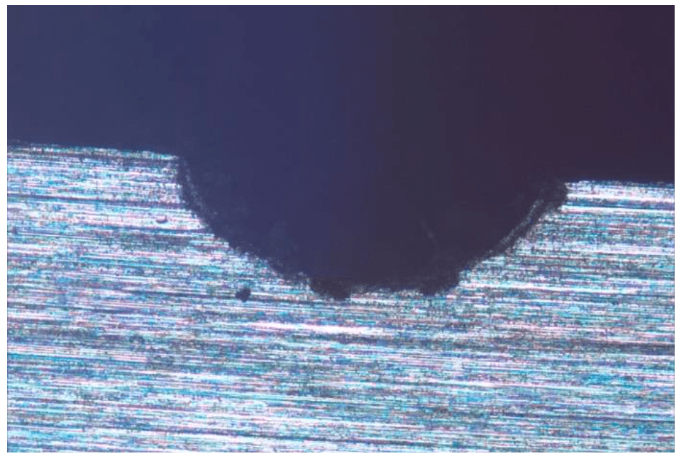
Fig.5. Cross thin section of 09ps steel plate at the cut point after exposure to the environment
During the exposure process, in order to ensure anodic control of the electrochemical reaction, which is necessary to show the effect of the stress state on the corrosion rate, the working solution is enriched with oxygen, which is achieved by continuously blowing air through the solution.
Processing of results
At the end of temperature conditioning, the bottom surface of the plate cut is cleaned from corrosion products with an eraser and the surface of the plates around the cut is cleaned from the protective varnish. At the same points as before the corrosion test, the cut depth of the plates Нi* is measured again (see table) and its increase ΔНi is determined as a result of the corrosive effects of the environment (Fig.5). The side surfaces of the plates are polished to obtain thin sections that, after etching, are used for metallographic analysis of the steel.
The arithmetic average of the increase in cut depth for all points is calculated:
where n = 13; mean square deviation
an actual increase in the cut depth is established
and the rate of the grooving corrosion of the plate materials is estimated
t – time of plates temperature conditioning; 8760 – hours in a year.
The distribution of cut depth changes along its length and the corrosion rates obtained using 09ps and 09G2S pipeline steels as examples are illustrated in the Table.
Cut depths at different points before and after exposure to corrosive environment, change of ΔНi and values of corrosion rates K of pipeline steels
|
Plate material |
Parameter |
Point number ni |
||||||||||||
|
1 |
2 |
3 |
4 |
5 |
6 |
7 |
8 |
9 |
10 |
11 |
12 |
13 |
||
|
Steel 09ps |
Нi, mm |
0.201 |
0.225 |
0.240 |
0.243 |
0.240 |
0.237 |
0.225 |
0.189 |
0.174 |
0.165 |
0.156 |
0.135 |
0.123 |
|
Нi*, mm |
0.210 |
0.234 |
0.252 |
0.255 |
0.246 |
0.252 |
0.231 |
0.195 |
0.183 |
0.180 |
0.165 |
0.150 |
0.141 |
|
|
ΔНi, mm |
0.009 |
0.009 |
0.012 |
0.012 |
0.006 |
0.015 |
0.006 |
0.006 |
0.009 |
0.015 |
0.009 |
0.015 |
0.018 |
|
|
ΔНav = 0.011 mm; S = 0.0038 mm; ΔНact = 0.011 ± 0.0038 mm; К = 2.3 ± 0.8 mm/year |
||||||||||||||
|
Steel 09G2S |
Нi, mm |
0.195 |
0.210 |
0.222 |
0.219 |
0.222 |
0.210 |
0.195 |
0.189 |
0.186 |
0.186 |
0.168 |
0.150 |
0.144 |
|
Нi*, mm |
0.201 |
0.219 |
0.231 |
0.225 |
0.231 |
0.225 |
0.204 |
0.195 |
0.192 |
0.189 |
0.174 |
0.165 |
0.162 |
|
|
ΔНi, mm |
0.006 |
0.009 |
0.009 |
0.006 |
0.009 |
0.015 |
0.009 |
0.006 |
0.006 |
0.003 |
0.006 |
0.015 |
0.018 |
|
|
ΔНav = 0.008 mm; S = 0.0044 mm; ΔНact = 0.008 ± 0.0044 mm; К = 1.8 ± 0.9 mm/year |
||||||||||||||
By comparing the K values, it can be concluded that 09G2S steel is more resistant to grooving corrosion in comparison with 09ps steel.
In addition to determining the comparative corrosion resistance of steels, the proposed technique allows investigating the effect of tensile and compressive stresses in the metal on the corrosion rate as well as the presence of the cut on the stressed structure. For this purpose, along with the surface of the plate around the cut, a protective varnish is applied to the plastic deformed curved part of the plate on its outer side, where the metal is exposed to compressive stresses, and also to the surface of the unstrained parts of the plate not exposed to any residual stresses. The protective coating is destructed at the indicated places of the plate at local points, the metal in which will be subjected to corrosive effects in subsequent tests. After carrying out corrosion tests, the protective varnish on plate surface around these points is removed. Then the difference in focal distance from the bottom point of the corrosion damage to the unaffected plate surface, taken as the depth of damage at that point, is determined. The necessary dependencies are obtained after performing experiments on plates prepared in this way, pre-curved to different deflection angles.
Conclusion
The technique has been developed for determining the corrosion rate of pipeline steels under conditions simulating corrosion damage of a field pipeline wall: when the pipe wall metal is in a stressed state, the presence of chlorine-ion in the water component of the oil-water emulsion, a channel in the form of a groove is present on the lower generatrix of the pipe, the water component is enriched with air oxygen. As an example for the application of the suggested technique, the corrosion rates of two pipeline steels 09ps and 09G2S were determined. Corrosion rates (2.3 ± 0.8 and 1.8 ± 0.9 mm/year) appeared to be close to those demonstrated by the materials of field pipelines subjected to grooving corrosion. The developed methodology can be used when investigating the effect of tensile and compressive stresses in the metal, as well as the presence of a cut on the stressed structure, on the corrosion rate.
References
- Litvinenko V.S., Tsvetkov P.S., Dvoynikov M.V., Buslaev G.V. Barriers to implementation of hydrogen initiatives in the context of global energy sustainable development. Journal of Mining Institute. 2020. Vol. 244, p. 428-438. DOI: 10.31897/PMI.2020.4.5
- Goldobina L.A., Orlov P.S. Analysis of the corrosion destruction causes in underground pipelines and new solutions for increasing corrosion steel’s resistance. Journal of Mining Institute. 2016. Vol. 219, p. 459-464. DOI: 10.18454/PMI.2016.3.459 (in Russian).
- Zainullin R.S. Mechanochemical fracture kinetics and resource of pipeline systems. Problemy sbora, podgotovki i transporta nefti i nefteproduktov. 2005. N 65, p. 44-63. DOI: 10.17122/ntj-oil-2005-65-44-63 (in Russian).
- Burkov P.V., Burkov V.P., Fat'yanov D.S., Timofeev V.Yu. Studying the Stress-Strain State of Oilfield Pipelines Exposed to Rill Corrosion. Bulletin of the Kuzbass State Technical University. 2018. N 3 (127), p. 5-12. DOI: 10.26730/1999-4125-2018-3-5-12 (in Russian).
- Vinogradov S.N., Volchikhin V.I., Shirina E.V., Meshcheryakov A.S. Study of corrosion resistance of structural steels in formation water. Izvestiya vysshikh uchebnykh zavedenii. Povolzhskii region. Tekhnicheskie nauki. 2008. N 4, p. 139-144 (in Russian).
- Kolikov A.P., Leletko A.S., Matveev D.B. et al. Investigation of residual stresses in welded pipes. Izvestiya vysshikh uchebnykh zavedenii. Chernaya metallurgiya. 2014. Vol. 57. N 11, p. 48-53 DOI: 10.17073/0368-0797-2014-11-48-53 (in Russian).
- Klisenko L.B., Lapshin A.P., Kudrin D.V. Probable reasons for the formation of ribbed corrosion in oilfield pipelines detected during technical diagnosis. Modern science: current problems and solutions. 2015. N 9 (22), p. 58-61 (in Russian).
- Lyubchik A.N., Krapivskii E.I., Bolshunova O.M. Prediction of the technical status of pipeline based on analysis. Journal of Mining Institute. 2011. Vol. 192, p. 153-156 (in Russian).
- Medvedev A.P. An integrated safety system for West Siberian field pipelines: Avtoref. dis. … d-ra tekhn. nauk. Ufa: Institut problem transporta energoresursov, 2004, p. 44 (in Russian).
- Firstov A.A., Kapachinskikh Zh.Yu., Seredenok V.A. et al. Justification of the possibility for assessing the level of bending stresses in the pipe walls of trunk gas and oil pipelines by determining its spatial position from the surface of the ground. Nauka i tekhnika v gazovoi promyshlennosti. 2020. N 2 (82) (in Russian).
- Bolobov V.I., Popov G.G., Batalov A.P. et al. Patent N 2730102. Method for assessing the resistance of pipeline steels to “rill” corrosion. Opubl. 17.08.2020 (in Russian).
- Podavalov A.K Reducing grooving corrosion of oil pipelines using cutting couplings: Avtoref. dis. … kand. tekhn. nauk. St.Petersburg: Sankt-Peterburgskii gosudarstvennyi gornyi institut im. G.V.Plekhanova, 2009, p. 20 (in Russian).
- Podoprigora A.A. The Research of Corrosion Damages on the Surface of Oil Pipeline after a Long-Term Exploitation. Bulletin of Yugra State University. Vol. 4 (23), p. 105-112 (in Russian).
- Popodko D.V. Assessment of the safe operation of shells with rill erosion using the finite element method: Avtoref. dis. … kand. tekhn. nauk. Ufa: Ufimskii gosudarstvennyi neftyanoi tekhnicheskii universitet, 2004, p. 24 (in Russian).
- Skoromnyi V.I. Developing methods and means to improve the safe operation of oil gathering pipelines: Avtoref. dis. … kand. tekhn. nauk. Ufa: Ufimskii gosudarstvennyi neftyanoi tekhnicheskii universitet, 2004, p. 24 (in Russian).
- Sultanmagomedov S.M. Ensuring the safe operation and durability of field pipelines subject to rill erosion: Avtoref. dis. … d-ra tekhn. nauk. Ufa: Ufimskii gosudarstvennyi neftyanoi tekhnicheskii universitet, 2003, p. 48 (in Russian).
- Shaymuhametov M.R. Tensions in the Area of Groove Destruction of Pipelines. Oil and Gas Business. 2009. N 2, p. 115-120 (in Russian).
- Shinkin V.N. Residual stresses during plastic torsion of a round bar. Sovremennye tendentsii razvitiya nauki i tekhnologii. 2016. N 3-3, p. 127-134 (in Russian).
- Shinkin V.N. Residual stresses during expansion of a steel pipe. Molodoi uchenyi. 2015. N 20 (100). Part 1, p. 88-93 (in Russian).
- Shchipachev A.M., Gorbachev S.V. Influence of post-welding processing on continuous corrosion rate and microstructure of welded joints of steel 20 and 30KHGSA. Journal of Mining Institute. 2018. Vol. 231, p. 307-311. DOI: 10.25515/PMI.2018.3.307
- Ren R.K., Zhang S., Pang X.L., Gao K.W. A novel observation of the interaction between the macroelastic stress and electrochemical corrosion of low carbon steel in 3.5 wt.% NaCl solution. Electrochimica Acta. 2012. Vol. 85, p. 283-294. DOI: 10.1016/j.electacta.2012.08.079
- Abaev Z.K., Galachieva S.V. Mathematical model elaboration in terms of baking time influence on the resistance to stress corrosion cracking under tension. International Conference on Industrial Engineering, Applications and Manufacturing (ICIEAM), 19-20 May 2016, Chelyabinsk, Russia. IEEE, 2016. Vol. 2, p. 1-4. DOI: 10.1109/ICIEAM.2016.7911569
- Aginey R.V., Firstov A.A., Kapachinskikh Z.Y. To the question of determining bending stress of a buried pipeline from the ground surface. International Conference on Innovations, Physical Studies and Digitalization in Mining Engineering (IPDME 2020), 23-24 April 2020, Saint Petersburg, Russian Federation. IOP, 2020. Vol. 1753. Iss. 1. N 012068. DOI: 10.1088/1742-6596/1753/1/012068
- Al-Mansour M., Alfantazi A.M., El-boujdaini M. Sulfide stress cracking resistance of API-X100 high strength low alloy steel. Materials & Design. 2009. Vol. 30, p. 4088-4094. DOI: 10.1016/j.matdes.2009.05.025
- Askari M.A., Aliofkhazraei M., Afroukhteh S. Сomprehensive review on internal corrosion and cracking of oil and gas pipelines. Journal of Natural Gas Science and Engineering. 2019. Vol. 71. p. 1-25. DOI: 10.1016/j.jngse.2019.102971
- Xinhua Wang, Xinghua Tang, Liwei Wang et al. Corrosion behavior of X80 pipeline steel under coupling effect of stress and stray current. International Journal of Electrochemical Science. 2014. Vol. 9. Iss. 8, p. 4574-4588. DOI: 10.3390/ma10070720
- Darowicki K., Orlikowski J., Arutunow A. Dynamic electrochemical impedance spectroscopy measurements of passive layer cracking under static tensile stresses. Solid State Electrochem. 2004. Vol. 8, p. 352-359. DOI: 10.1007/s10008-003-0470-0
- Dergach Т.О., Sukhomlin G.D. Methods for the Improvement of Corrosion Resistance of Low-Alloy Steel Pipes for the Oil-And-Gas Extraction Industry. Mater Science. 2021. Vol. 56. Iss. 5, p. 684-690. DOI: 10.1007/s11003-021-00483-9
- Griggs J., Gamboa E., Lavigne O. A review of modelling high pH stress corrosion cracking of high-pressure gas pipelines. Materials and Corrosion. 2015. Vol. 67. Iss. 3, p. 251-263. DOI: 10.1002/maco.201508454
- Hasan F., Iqbal J., Ahmed F. Stress corrosion failure of high-pressure gas pipeline. Engineering Failure Analysis. 2007. Vol. 14. Iss. 5, p. 801-809. DOI: 10.1016/j.engfailanal.2006.11.002
- Zhan-Feng Chen, Wen Wang, He Yang et al. On the effect of long corrosion defect and axial tension on the burst pressure of subsea pipelines. Applied Ocean Research. 2021. Vol. 111. N 102637. DOI: 10.1016/j.apor.2021.102637
- Sultanbekov R., Islamov S., Mardashov D. et al. Research of the Influence of Marine Residual Fuel Composition on Sedimentation Due to Incompatibility. Journal of Marine Science and Engineering. 2021. Vol. 9. Iss. 10. N 1067. DOI: 10.3390/jmse9101067
- Saleem B., Ahmed F., Asif Rafiq M. et al. Stress corrosion failure of an X52 grade gas pipeline. Engineering Failure Analysis. 2014. Vol. 46, p. 157-165. DOI: 10.1016/j.engfailanal.2014.08.011
- Sultanbekov R.R., Nazarova M.N. The influence of total sediment of petroleum products on the corrosiveness of the metal of the tanks during storage. E3S Web Conf. I International Conference “Corrosion in the Oil and Gas Industry”, 22-24 May 2019, Saint Petersburg, Russia. E3S Web of Conferences, 2019. Vol. 121. N 01015. DOI: 10.1051/e3sconf/201912101015
- Krivokrysenko E.A., Popov G.G., Bolobov V.I., Nikulin V.E. Use of Magnetic Anisotropy Method for Assessing Residual Stresses in Metal Structures. Key Engineering Materials. 2020. Vol. 854, p. 10-15. DOI: 10.4028/www.scientific.net/KEM.854.10