Allocation of a deep-lying brine aquifer in the rocks of a chemogenic section based on the data of geophysical well logging and 2D seismic exploration
- 1 — канд. геол.-минерал. наук Associate Professor Saint Petersburg Mining University ▪ Orcid ▪ Elibrary ▪ Scopus ▪ ResearcherID
- 2 — Ph.D. Associate Professor Saint Petersburg Mining University ▪ Orcid ▪ Elibrary ▪ Scopus ▪ ResearcherID
- 3 — Postgraduate Student Saint Petersburg Mining University ▪ Orcid ▪ Elibrary ▪ ResearcherID

Abstract
Advancement in the production of potassium fertilizers is an important strategic task of Russian agricultural industry. Given annually growing production rates, the reserves of discovered potassium-magnesium salt deposits are noticeably decreasing, which creates the need to ensure stable replenishment of the resource base through both the discovery of new deposits and the exploitation of deep-lying production horizons of the deposits that are already under development. In most cases, deposits of potassium-magnesium salts are developed by underground mining. The main problem for any salt deposit is water. Dry salt workings do not require any additional reinforcement and can easily withstand rock pressure, but with an inflow of water they begin to collapse intensively – hence, special attention is paid to mine waterproofing. Determination of spatial location, physical and mechanical properties of the aquifer and water-blocking stratum in the geological section represent an important stage in the exploration of a salt deposit. The results of these studies allow to validate an optimal system of deposit development that will minimize environmental and economic risks. On the territory of Russia, there is a deposit of potassium-magnesium salts with a unique geological structure – its production horizon lies at a considerable depth and is capped by a regional aquifer, which imposes significant limitations on the development process. To estimate parameters of the studied object, we analyzed the data from CDP seismic reflection survey and a suite of methods of radioactive and acoustic well logging, supplemented with high-frequency induction logging isoparametric sounding (VIKIZ) data. As a result of performed analysis, we identified location of the water-bearing stratum, estimated average thickness of the aquifers and possible water-blocking strata. Based on research results, we proposed methods for increasing operational reliability of the main shaft in the designed mine that will minimize the risks of water breakthrough into the mine shaft.
None
Introduction
The main method for extracting salt from the subsoil is heavy equipment mining. This recovery method has a number of advantages: relatively quick extraction of salt from the pillar and transportation to the surface for further processing and concentration.
Under the conditions of increased rock pressure, salt is a plastic and fluid material, which rapidly begins to dissolve and collapse upon its contact with water [14, 26]. Therefore, the main problem of any underground salt mining facility is the presence of aquifers in the geological section [29]. Deposit development should be accompanied either by measures that inhibit water seepage or by complete waterproofing of the working, which is hard to achieve under real mining conditions [17]. The main method for inhibiting water inflows to the production horizon under development is using a room-and-pillar mining system with support of the water-blocking strata [2].
In the longstanding practice of salt mining, there were numerous accidents related to gas-dynamic phenomena [1] and flooding of the mines with brine waters from overlying carbonate deposits, composed of clay-marl layers, dolomitic rocks, etc. [11-13]. Overall, in the history of salt production until now there are about 100 flooded mines in different countries, including Winnfield (USA), Vansсoy and Patience Lake (Canada), Holle (Congo), von der Heydt, Agatha and Manteuffel (Germany). In Russia, the largest salt mining accidents were the floodings of the first and third mines in Berezniki, which were never restored and remained flooded [3].
The most environmentally acceptable method for developing salt deposits is room-and-pillar mining, which implies that after ore extraction and concentration, waste rock returns to the mining site to maintain rock pressure and prevents the mine from collapsing. This excludes rock dumping on the surface, significantly reduces financial burden on the subsoil user and environmental burden on the development area [15, 22, 25].
The main routes of brine water infiltration are tectonic faults and fractures generated in-situ during rock mass formation, as well as man-made cracks, which occur due to unsustainable development of deposits and lead to emergency situations [7, 28]. Hence, it is a very relevant task to carry out detailed study of the deposit at the preparatory stage to obtain a priori data about the formation: its geometrical parameters, physical and mechanical properties, presence of tectonic fractures [8, 24, 32]. Obtained information allows to validate the location of the water-blocking stratum – a thick fluid seal that will protect the working from brine infiltration. Geophysical monitoring, aimed at early detection of fractures and weakened layers that transform under the influence of brine, allows to maintain operational control over the working and update the reserves of the deposit.
The main methods for studying salt deposits include common-depth point (CDP) seismic reflection survey, electrical prospecting, well measurements by means of gamma-ray logging (GRL), neutron gamma-ray logging (NGRL), spectrometric gamma-ray logging (SGRL), acoustic logging (AL), electric logging. A full set of methods is selected individually for each formation based on geological structure of the studied area and depth of the production interval.
In this work, we study the specifics of the Vyatka regional aquifer distribution by means of CDP seismic reflection survey and well logging at the N deposit of potassium-magnesium salts.
Greenfield exploration of the deposit involved seismic prospecting within the first and second subsoil blocks. We examined the materials of archive reports on geological structure, hydrogeological conditions of the studied area, as well as the results of geophysical logging of previously and newly drilled wells. The main task of studying these methods is to develop criteria for detecting a water-bearing layer in the section, identify fluid seals to validate a water-blocking stratum and search for fracture zones near the wellbore.
Since the N deposit has not been brought into development yet, the research results will serve as a priori information for further monitoring and may become the basis for the main shaft sinking method.
Literature review
Currently, a large number of Russian and foreign researchers study the issues of developing deep-lying deposits of potassium and magnesium salts in the presence of aquifers in the geological section [17]. Numerous works are devoted to the problems associated with the accidents that have occurred in the course of deposit development [2]. Accidents at potassium and magnesium mines can be caused by water leakage from aquifers near the deposit, as well as by gas-dynamic phenomena [8, 10, 11]. Various types of mine accidents have been reported in Canada, Germany, Ukraine and Russia, some of them have affected neighboring mines and territories. For example, during the accident in Solikamsk in 1995, the earth's surface above the mine sank by 4.5 m in one day; in the Krugerhall mine in 1989, the cause of the accident was a seismic signal with a magnitude of 5.5. Insufficient information about hydrogeological conditions of the mine field also led to a number of serious mine accidents [30]. A salt mine in Canada was flooded in 1985, a similar accident occurred in 1997. However, in Canada, a number of successful measures have been applied to prevent mine flooding by injecting cement slurry into the underground space through a network of wells [9, 10]. In Russia, the latest accidents were recorded at the Verkhnekamsk mine in 1986 and 2006. These accidents were associated with the flooding of two mines at the deposit. Estimations were made for possible routes of water infiltration from the anomalous zones of the geological massif. Such areas were represented by fracture zones of the aquifers, which had formed in the process of commercial development [14].
Mine floodings occur in different countries, and there is no single solution to prevent such accidents [18, 20, 21]. Researchers propose implementation of geophysical methods of monitoring mine shafts for early detection of water presence in the underground space, as well as monitoring stress state of the rock mass using seismic methods. The main methods of monitoring observations at the Verkhnekamsk deposit are surface and mine electrical prospecting, seismic and gravity exploration [3, 27]. However, these methods are very expensive, and their application in monitoring is only a recommendation. Many deposits of potassium-magnesium salts do not use them in the development process, although their application would solve numerous critical issues of accident prevention [4-6, 9, 31].
A large number of studies are related to the methods of mathematical modeling of possible water presence, stress state of the rock mass and the methods of reservoir development [23, 31]. These statistical estimates allow to approximate the risks arising from deposit development, calculate economic and environmental consequences of possible accidents and propose solutions to some of them [15, 16, 19, 20].
The main conclusions were drawn from the analysis of global research in the area of salt deposits: salt mines are constantly being exposed to geological and economic risks, and these risks should be taken into account at the stage of development planning. It is necessary to perform monitoring observations in the zones of water infiltration into the underground space of mines and to estimate integrity of the water-blocking strata using geophysical methods.
Methodology
In the scope of this research, the following goals and objectives have been set:
- examination of archive materials for the region of interest, which contain description of geological structure, stratigraphy and hydrogeology of the studied area;
- examination of reports on performed CDP seismic reflection surveys by area;
- loading and visualization of logging data from 33 wells with an average length of 1,200-1,300 m and their subsequent interpretation;
- identification of patterns in the strike of the Vyatka aquifer based on the data of seismic prospecting and a suite of geophysical well logging surveys.
In the studied blocks 1 and 2, we analyzed available materials of geophysical well logging in order to determine and update the geological structure of the studied section within the depth interval of 950-1,200 m, with subsequent identification of potential aquifers.
Analysis of geophysical well logging materials in the block 1 allowed to classify the wells into five different well logging suites. As reference wells for studying distribution patterns of physical properties of the Vyatka aquifer, we selected wells with the most complete well logging suite and lithological column: ххх1, ххх2, ххх3, ххх4 (Fig.1).
In a group of these wells, we used the methods of gamma-ray logging (GRL), neutron-thermal neutron logging (NTL), caliper logging (Dn), gamma-gamma density logging (GGL-D), resistivity logging (RL) with gradient and potential probes, high-frequency induction logging isoparametric sounding (VIKIZ), acoustic logging (AL).
In the remaining wells, the suite was significantly smaller and in some wells it was represented only by GRL, NTL and Dn methods. However, despite this, obtained materials were enough to identify the main patterns of the Vyatka aquifer distribution and determine its spatial position within the studied area.
CDP seismic reflection survey within the studied blocks was carried out in 2014, in addition to that we reprocessed and reinterpreted data of seismic prospecting performed earlier, in 1980-1990s. In order to meet the goals and objectives set in this work, we used structural maps, obtained in the course of processing and interpretation of seismic data on the main reflecting horizons (top of salt, top of Permian, bottom of Permian). For data comparison and acquisition of more reliable information, we also used deep seismic geological sections passing through the studied area and crossing wells.
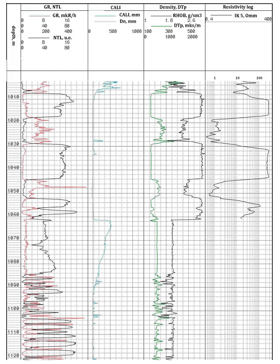
Fig.1. Example of well logging data plot for the well ххх1 in the interval of geological interest
Geological structure of the subsoil area of a potassium-magnesium salt deposit involves Proterozoic and Phanerozoic formations of various genesis and composition. The Early Proterozoic formations, which make up the crystalline basement, lie at the depth of 1,100-3,350 m with a general westward dip. The Phanerozoic sedimentary mantle is represented by deposits of the Cambrian, Ordovician, Silurian, Permian, Triassic, Jurassic, Cretaceous ages and formations of the Quaternary system.
Based on the lithology of the research object, the studied interval within the range of 950-1,200 m is represented by the interbedding of anhydrides, limestones, marls, clays and dolomites. The water-bearing layers, confined to the Vyatka aquifer, are represented by the interbedding of dolomites, marls and limestones with inclusion of clayey material. A specific characteristic of the studied interval is the presence of anhydrite rock layers, which are fluid seals, above and below the studied water-bearing strata. Taking into account lithology specifics of the studied interval, the water-bearing rock layers are expected to be intensely fractured to accumulate water in them. However, based on available geological and geophysical information, it is only possible to provide spatial correlation and interpolation of the intervals of interbedded dolomites, marls and limestones with inclusion of clayey material, without assessing spatial distribution of fracturing in the rock mass of the Vyatka aquifer, which directly affects examination of hydrogeological properties of the rock mass.
To validate specific characteristics of geophysical data distribution in the studied interval and above it, we selected three reference horizons:
- clay layer, lying above the studied strata and characterized by elevated GRL values – 9 μR/h, low NTL values – 1 c.u., presence of caverns according to caliper log data, density around 2.4 g/cm3, elastic wave velocity around 3,500 m/s;
- anhydrite layer, lying at the top of the studied interval and characterized by low GRL values – 2-4 μR/h, high NTL values – 60 c.u., density around 3 g/cm3, high elastic wave velocity – around 6,200 m/s;
- salt layer, lying below the studied strata and characterized by low GRL values – 3-5 μR/h, high NTL values – 45-70 c.u., density around 2.2 g/cm3, elastic wave velocity around 4,600 m/s.
Next, it is required to identify manifestation patterns of Vyatka aquifer rocks and anhydrites according to well logging data. The anhydrite layer is determined by the following indicators of the logging curves (Fig.1, depth interval of 1,008-1,018 m): low radioactivity – around 1-2 μR/h; high NTL value (low hydrogen content) – around 70 c.u. at the top and 55 c.u. at the bottom of the layer; low elastic wave travel time – around 170 μs/m, which corresponds to a velocity of 5,880 m/s; elevated density readings – 3.0 g/cm3 according to GGL-D data. The thickness of observed anhydrites, according to logging data from different wells, ranges from 8 to 20 m.
The main characteristics of well logging curves include: a variation of NTL readings from the top to the bottom, which may be associated with changes in the mineral composition; a smooth increase in GRL values from the top to the bottom of the formation; homogeneity of the reservoir in terms of its velocity properties and density.
The next layer to be identified according to the well logging curves is the first aquifer, represented by the interbedding of marls and dolomites (Fig.1, depth interval of 1,018-1,028 m). This aquifer is characterized by the following geophysical parameters: elevated values of radioactivity – 8-10 μR/h; low NTL values – 2.5 c.u.; increased elastic wave travel time through the rock – around 270 μs/m, which corresponds to a velocity of 3,700 m/s; density values, decreased in comparison to the host rocks, determined using GGL-D and equal to 2.4 g/cm3.
At the top of the layer, we observed higher values of radioactivity, which characterized the interlayer of marls. However, this pattern was not registered in all of the wells, which makes it difficult to determine the exact boundary of interbedding between marls and dolomites in other wells.
Anhydrite layer with a thickness of 7.6-29 m acts as a fluid seal between the first and the second aquifers. Geophysical data parameters in this layer are similar to those of the overlying anhydrite layer.
The second aquifer is represented by the interbedding of dolomites and clays (Fig.1, depth interval of 1,044-1,052 m). According to geophysical data, it is characterized by variable parameters from the top to the bottom of the layer.
Criteria for identifying the second aquifer based on logging data include: elevated and average radioactivity readings according to GRL – about 10.5 at the top and 3.76 μR/h at the bottom of the formation; low NTL readings – about 2.2 c.u.; increased elastic wave travel time – from 250 μs/m at the top and up to 200 μs/m at the bottom of the formation, which corresponds to velocities of 4,000 and 5,000 m/s; density values, decreased in comparison to the host rocks within the range of 2.47-2.7 g/cm3 from the top to the bottom.
The characteristics of well logging curves include: high GRL values at the top of the formation compared to the bottom; increase in the readings of NTL curve from the top to the bottom; decrease in elastic wave travel time from the top to the bottom; increase in density from the top to the bottom.
This implies the presence of interbedding between two types of rocks with different physical properties, with clayey rocks presumably lying in the top of the formation, and dolomite lying in the bottom.
Based on the data obtained while studying the depth interval, we created a table of physical rock properties by wells (Table 1), which contains average values of physical parameters recorded by geophysical well logging.
Table 1
Average values of well logging curves against the main lithological rock types in the studied interval
|
Rock type |
GRL,μR/h |
NTL, c.u. |
Density, g/cm3 |
AL, μs/m |
Velocity, m/s |
|
Dolomite |
6.05 |
2.3 |
2.44 |
256 |
3,906.25 |
|
Marl |
6.87 |
3.88 |
2.41 |
240 |
4,166.67 |
|
Limestone |
6.95 |
2.96 |
2.5 |
253 |
3,952.57 |
|
Anhydrite |
2.9 |
28.92 |
3.1 |
168 |
5,952.38 |
|
Dark clay |
12.32 |
2.95 |
2.3 |
202 |
4,950.50 |
|
Salt (halite) |
3.46 |
49 |
2.1 |
217 |
4,608.29 |
Based on the analysis of geological and physical data, we compiled a table of physical properties of the rocks that compose the studied section, according to which the following observations can be highlighted:
- rocks of the Vyatka aquifer are characterized by elevated radioactivity readings, decreased NTL values, decreased density compared to anhydrides, increased interval travel time of an elastic wave according to acoustic logging data, decreased values of electrical resistivity, low values of self-potential (SP) logging;
- the host strata of the Vyatka aquifer is composed of anhydrite, which is characterized by low values of radioactivity, high readings of neutron logging, a decrease in the interval travel time of an elastic wave through the rock, high values of electrical resistivity and SP, increased density;
- the layer underlying the anhydrites, which is represented by black clayey rocks, is pervasive and characterized by a local increase in GRL values and average density around 2.5 m.
The main result of tracing the rocks of the Vyatka aquifer was the creation of our own database for all wells and the interwell space, which allowed us to draw structural maps of aquifer tops and effective thickness maps. An example of a structural map for two blocks of the N deposit is presented in Fig.2.
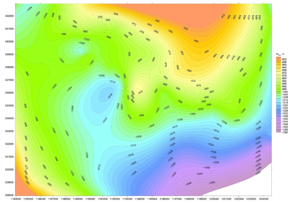
Fig.2. Structural map of the top of aquifer 1
The database includes information on the lithology of the studied strata of the Vyatka aquifer, average readings of the logging curves recorded in the wells, depth marks indicating the top, bottom and thickness of each aquifer. By means of a suite of well logging surveys and well lithology, a thin layer of clayey rocks was traced at the bottom of the anhydrites above the accumulations of salt.
As can be seen from Fig.2, the top of the Vyatka aquifer dips to the south-east. In the central part of the map, there is also a zone with rapid gradient changes of absolute depth marks, which may be associated with tectonic specifics of studied area formation. The depth difference is about 100 m.
The map of effective thickness (Fig.3) demonstrates a consistent value of aquifer thickness around 9-10 m. In the central part of the map, same as on the absolute depth map, one can observe a disturbance in thickness correlation, which is explained by the tectonics of this region.
In 2019, as part of the hydrogeological studies of the Vyatka aquifer rocks, experimental pumping was carried out in the wells located near the proposed mine shaft, and water samples were taken for chemical analysis. The contractor performed pumping tests using the bailing method in the aquifer interval, after which experimental pumping was performed by the same method with restoration of the groundwater table to a static level, which was 43.6 and 16.9 m above ground level for the first and second aquifers, respectively. Subsequently, filtration coefficient and predicted discharge were calculated for each aquifer. For the first one, the permeability coefficient was 0.046 m2/day, the filtration coefficient was 0.0055 m/day; for the second one, the permeability coefficient was 0.013 m2/day, the filtration coefficient was 0.0011 m/day. The volume of water inflow into the mine 11 m in diameter was calculated using the “big well” formula and amounted to 63 and 20 m3/day for each of the strata, respectively. All calculations were carried out based on hydrogeological studies, taking into account average thickness (about 8.3 and 11.9 m) of two aquifers in the studied well, located in the direct proximity to the proposed mine shaft. Based on the analysis of samples taken during experimental hydrogeological survey in the wells, it was revealed that the waters of the studied horizons belonged to Permian deposits, their chemical composition included heavy-brine (according to E.V.Pinneker) chloride and sodium solutions with mineralization from 170.6-185.3 to 199.8-234.0 g/l; the water was very hard, in terms of pH value it varied from neutral to slightly alkaline.
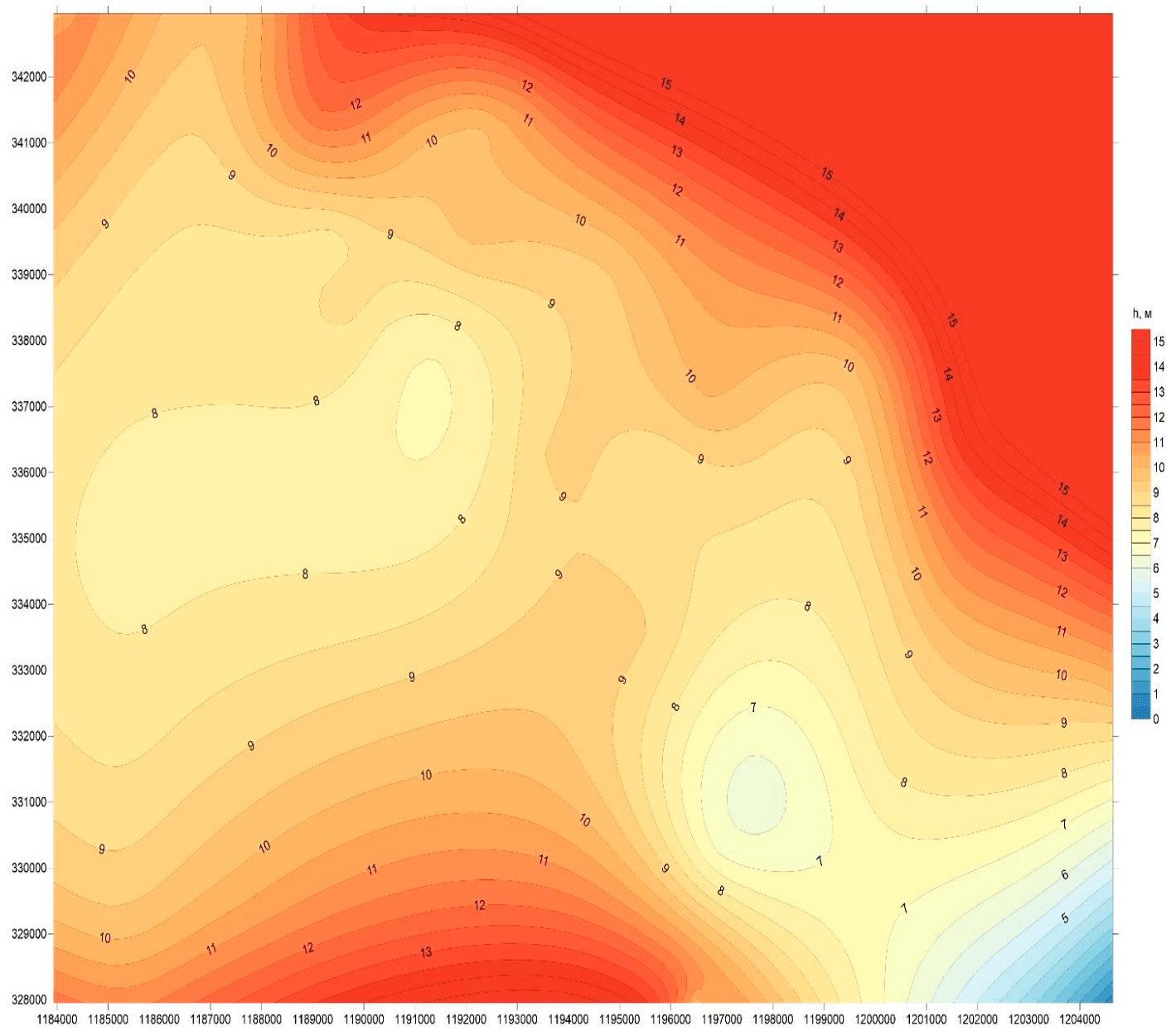
Fig.3. Effective thickness map for the rocks of the first water-bearing interval of the Vyatka aquifer
As regards the degree of water aggressiveness towards concrete structures in terms of SO4, for Portland cement of the first sulfate resistance group, the waters vary from highly aggressive (W4-W14) to moderately aggressive (W16-W20); for Portland cement and slag Portland cement of the second group, they are defined as medium aggressive (W4) and slightly aggressive (W6). The degree of aggressiveness to the carcasses of reinforced concrete structures in terms of Cl in the zone of variable water level is high. According to radiological parameters, the groundwaters of the studied aquifers are considered safe.
Discussion
The objective of the research was to study geological structure and hydrogeological conditions and to trace the rocks of the Vyatka aquifer, represented by the interbedding of carbonate and clayey rocks. Based on provided initial data for the wells of license blocks 1 and 2, we developed a method for identifying the rocks of the Vyatka aquifer, represented by the interbedding of dolomites, limestones and marls, and overlying sediments composed of anhydrites, clayey rocks and salt accumulations (halites).
Vyatka aquifer is represented by two water-bearing strata, the first one is composed of marls at the top of the formation and dolomites at the bottom, the second one is composed of dolomites and clayey rocks. The host strata is represented by fractured dolomites and limestones.
The essence of the method was to identify specific features of the recorded logging curves for each type of the rocks that compose the studied depth interval and to compare these readings with lithological columns for the wells ххх1, ххх2, ххх3, ххх4.
Subsequently, this method was used in the wells with no detailed lithological description of the rocks and a limited suite of well logging surveys, and on its basis we determined the lithology of the Vyatka aquifer in the wells of the blocks 1 and 2.
The result of the study was a database of wells, which displayed the depths indicating the top, bottom and thickness of the rocks of the Vyatka aquifer, as well as the average values of the well logging curves (Table 2).
Table 2
Fragment of a database for the first water-bearing strata of the Vyatka aquifer
|
Well |
First water-bearing strata |
Well logging readings |
|||||||
|
Нl, m |
h, m |
Lithology |
GRL, μR/h |
NTL, c.u. |
SP, mV |
AL, μs/m |
RL, Ohm∙m |
Density, g/cm3 |
|
|
ххх1 |
–1,007.00 |
10.00 |
Dolomites, marls, clays |
8.45 |
– |
– |
– |
– |
– |
|
ххх2 |
–1,016.00 |
8.00 |
Dolomites, marls, clays |
7.8 |
1.7 |
–321 |
– |
7.2 |
2.02 |
|
ххх3 |
–1,020.00 |
9.60 |
Dolomites, marls, clays |
7.8 |
1.32 |
–344 |
– |
6.16 |
2.33 |
|
ххх4 |
–1,008.60 |
9.00 |
Dolomites, marls, clays |
6.88 |
1.68 |
–220 |
– |
– |
2.37 |
|
ххх5 |
–1,019.40 |
9.60 |
Dolomites, marls, clays |
7.8 |
1.44 |
–276 |
– |
6 |
2.43 |
|
ххх6 |
–1,010.00 |
10.00 |
Dolomites, marls, clays |
6.87 |
1.92 |
–54.3 |
– |
6.4 |
2.15 |
|
ххх7 |
–989.00 |
13.80 |
Dolomites, marls, clays |
8.43 |
3.61 |
–244 |
– |
4.8 |
2.44 |
|
ххх8 |
–1,010.00 |
7.60 |
Dolomites, marls, clays |
7.55 |
1.61 |
–265 |
– |
2.4 |
2.31 |
Conclusions
Using the created database, we drew structural maps of the formation top and isopach maps that displayed the distribution of the Vyatka aquifer in the studied area.
In the course of hydrogeological studies, we calculated the filtration coefficient for the first Vyatka aquifer, equal to 0.0055 m/day, and the thickness of water-bearing rocks, reaching 8.3 m; taking into account the obtained parameters, predicted water inflow into the mine shaft was estimated at 63 m3/day.
In the interval of the second Vyatka aquifer, the filtration coefficient was 0.0011 m/day, the thickness of water-bearing rocks reached 11.9 m; given the calculated parameters, predicted water inflow into the mine shaft was 20 m3/day.
As a result of analyzing calculated data, a conclusion was made about the feasibility of introducing special drilling methods for further construction of the vertical shaft at the deposit of potassium-magnesium salts. Under the conditions of potassium salt deposit development, flooding protection is mainly ensured by maintaining a homogeneous water-blocking stratum (WBS) of the required thickness over the production (salt) layer and selection of development method parameters corresponding to the actual WBS thickness. Thus, water-conducting fractures, which form in the process of underground operations and lie above the salt layers under development, should not reach the WBS top through the overlying layers of anhydrites, dolomites and marls with a minimum thickness of 10-15 m.
Safe development of the WBS is determined by controlling the overall thickness of WBS layers, in which deformation of the mined rock strata does not lead to formation of man-made cracks.
Special measures for dealing with the inflow of brines in case of waterproofing failure in the mine include:
- construction of watertight bulkheads in the underground working, which will quickly separate the flooded zone from other blocks;
- plugging of man-made cracks between the underground workings and aquifers by filling them with cement slurry;
- erection of groundwater traps in the mine tunnels with their subsequent discharge into the gob or to the surface of the mine.
Flooding can be avoided by means of ensuring that the extraction of potassium salts takes place at the deposits, where overall thickness of the overlying sediment layers, in which deformation of the rock strata does not cause fracturing, exceeds the minimum permissible total thickness of interbedded WBS layers.
According to the results of processed data from the deposit wells, the water-blocking stratum, represented by the interbedding of dolomites, marls and limestones, and the overlying strata of anhydrites and clayey rocks above the salt layer, have an overall thickness of more than 15 m, which creates conditions for safe construction and further operation of the mine for the extraction of potassium and magnesium salts.
References
- Baryakh A.A., Andreiko S.S., Fedoseev A.K. Gas-dynamic roof fall during the potash deposits development. Journal of Mining Institute. 2020. Vol. 246, p. 601-609. DOI: 10.31897/PMI.2020.6.1
- Baryakh A.A., Gubanova E.A. On flood protection measures for potash mines. Journal of Mining Institute. 2019. Vol. 240, p. 613-620. DOI: 10.31897/PMI.2019.6.613
- Vagin V.B., Efimov A.M., Kulagov E.V. Issledovanie i otsenka sostoyaniya vodozashchitnogo sloya nad kaliinymi gorizontami geofizicheskimi metodami. Gornyi Zhurnal. 2014. N 2, p. 11-15 (in Russian).
- Glebov S.V. Validation of the Initial Data for the Assessment of Informative Value of Geophysical Methods in the Development of Verkhnekamsk Salt Deposit. Gornyi informatsionno-analiticheskii byulleten. 2005. N 9, p. 75-78 (in Russian).
- Zubov V.P., Smychnik A.D. The concept of reducing the risks of potash mines flooding caused by groundwater inrush into excavations. Journal of Mining Institute. 2015. Vol. 215, p. 29-37 (in Russian).
- Kvitkin S.Y., Trofimov V.I., Kovalskaya V.V. Environmental efficiency and legal possibility of mineralized water dispose in the suprasalt sequence of the verkhnekamskoe deposit. Journal of Mining Institute. 2017. Vol. 228, p. 731-737. DOI: 10.25515/PMI.2017.6.731
- Kobylkin S.S., Kharisov A.R. Design features of coal mines ventilation using a room-and-pillar development system. Journal of Mining Institute. 2020. Vol. 245, p. 531-538. DOI: 10.31897/ PMI.2020.5.4
- Kolesov E.V., Shalimov A.V., Semin M.A. Development of the activities for explosive gases removal from the worked-out area in case of potash mine flooding. Promyshlennaya bezopasnost. 2019. N 12, p. 60-65. DOI: 10.24000/0409-2961-2019-12-60-65 (in Russian).
- Kologrivko A. Decrease in geoecological consequences by underground mining of potash fields. Vestnik Polotskogo gosudarstvennogo universiteta. Seriya F. Prikladnye nauki. Stroitelstvo. 2014. N 16, p. 101-110 (in Russian).
- Konstantinova S.A., Solovev V.A., Vaulina I.B. On the Assessment of Geomechanical Role of Gob Filling at Potash Mines. Geodinamika i napryazhennoe sostoyanie nedr Zemli: Trudy Vserossiiskoi konferentsii, posvyashchennoi 80-letiyu akademika M.V.Kurleni (s uchastiem inostrannykh uchenykh), 3-6 oktyabrya, 2011, Novosibirsk, Rossiya. 2011. Vol. 1, p. 394-399 (in Russian).
- Laptev B.V. Accidents at Verkhnekamsk Deposit of Potassium-Magnesium Salts. Bezopasnost truda v promyshlennosti. 2009. N 8, p. 28-31 (in Russian).
- Laptev B.V. Historiography of Accidents during the Development of Salt Deposits. Promyshlennaya bezopasnost. 2011. N 12, p. 41-46 (in Russian).
- Pachgin V.V. Validation of Intensive Stoping Technology of Flat Potassium-Magnesium Seams below the Aquifers. Problemy nedropolzovaniya: Sbornik nauchnykh trudov. Ch. 1. Natsionalnyi mineralno-syrevoi universitet “Gornyi”. St. Petersburg, 2015, p. 82-83 (in Russian).
- Zubov V.P., Kovalski E.R., Antonov S.V., Pachgin V.V. Improving the safety of mines in developing Verkhnekamsk potassium and magnesium salts. Gornyi informatsionno-analiticheskii byulleten . 2019. N 5, p. 22-33. DOI: 10.25018/0236-1493-2019-05-0-22-33 (in Russian).
- Sirenko Yu.G., Kovalskii E.R. Improvement of Selective Potash Extraction Using Shortwall Mining with Partial Backfill. Gornyi zhurnal. 2016. N 1, p. 24-26. DOI: 10.17580/gzh.2016.01.05 (in Russian).
- Shkuratskiy D.N., Rusakov M.I. Using industrial wastes of potash manure production at rock mixtures for backfilling gobs. Izvestiya Tulskogo gosudarstvennogo universiteta. Nauki o Zemle. 2015. N 3, p. 87-97 (in Russian).
- Asanov V.A., Pankov I.L., Evseev A.V. et al. Experimental and theoretical research of long term stability of load-carrying elements of the room-and-pillar system of potash beds. Vestnik Permskogo nauchnogo tsentra. 2017. N 1, p. 8-14 (in Russian).
- Jie C., Liu J.-X., Jiang D.-Y. et al. An experimental study of strain and damage recovery of salt rock under confining pressures. Rock and Soil Mechanics. 2016. Vol. 37. N 1, p. 105-112. DOI: 10.16285/j.rsm.2016.01.012
- Barker J., Gundiler I. New Mexico potash – past, present, future. New Mexico Earth Matters. 2008. Vol. 8. N 2, p. 1-6.
- Belkhiri L., Narany T.S. Using multivariate statistical analysis, geostatistical techniques and structural equation modeling to identify spatial variability of Groundwater quality. Water Resources Management. 2015. Vol. 29, p. 2073-2089. DOI: 10.1007/s11269-015-0929-7
- Cocker M.D., Orris G.J., Wynn J. U.S. geological survey assessment of global potash production and resources – A significant advancement for global development and a sustainable future. Geoscience for the public good and global development: Toward a sustainable future: Geological Society of America Special Paper. 2016. Vol. 520, p. 89-98. DOI: 10.1130/2016.2520(10)
- Cocker М.D, Orris G.J. World potash developments. Proceedings of the 48th Annual Forum on the Geology of Industrial Minerals, 30 April – 4 May, 2012, Scottsdale, Arizona, USA. Arizona Geological Survey, 2013. Chapter 1, p. 1-16.
- Li W., Han Y., Wang T., Ma J. DEM micromechanical modeling and laboratory experiment on creep behavior of salt rock. Journal of Natural Gas Science and Engineering. 2017. Vol. 46, p. 38-46. DOI: 10.1016/j.jngse.2017.07.013
- Khaustov V.V., Ustiugov D.L. Formation of drainage waters of Tyrnyauz deposit in ecological aspect. IOP Conference Series: Earth and Environmental Science. 2017. Vol. 87. Iss. 4. N 042006. DOI: 10.1088/1755-1315/87/4/04200
- Kowalewski O, Śpiewanowski P. Stock market response to potash mine disasters. Journal of Commodity Markets. 2017. Vol. 20, p. 1-45. DOI: 10.1016/j.jcomm.2020.100124
- Litvinenko V. Advancement of geomechanics and geodynamics at the mineral ore mining and underground space development. Geomechanics and Geodynamics of Rock Masses: International European Rock Mechanics Symposium (EUROCK 2018), 22-26 May, 2018, St. Petersburg, Russian Federation. OnePetro, 2018. Vol. 1, p. 3-16.
- Ponomarenko T. Ecological, economic and social consequences of emergencies on potash mines. Management Systems in Production Engineering. 2012. Vol. 2. Iss. 6, p. 28-31.
- Pospehov G.B., Pankratova K.V., Straupnik I.A. Geoengineering researches for the restoration of the lands disturbed by mining operations. Engineering and Mining Geophysics 2018 – 14th Conference and Exhibition, 23-27 April, 2018, Almaty, Kazakhstan. European Association of Geoscientists & Engineers, 2018. Vol. 2018, p. 1-5. DOI: 10.3997/2214-4609.201800528
- Rudakov M., Gridina E., Kretschmann J. Risk-based thinking as a basis for efficient occupational safety management in the mining industry. Sustainability. 2021. Vol. 13. Iss. 2, p. 470. DOI: 10.3390/su13020470
- Whyatt J, Varley F. Catastrophic Failures of Underground Evaporite Mines. Proceedings of the 27th International Conference on Ground Control in Mining, 29-31 July, 2008, Morgantown, USA. College of Engineering and Mineral Resources, West Virginia University, 2008, p. 1-10.
- Zubov V.P., Smychnik A.D. Exploration method of potash and magnesium salts of the complex structure at great depths. Ecology, Environment and Conservation. 2017. Vol. 23, Iss. 3, p. 1697-1701.
- Zuev B.Y, Zubov V.P., Fedorov A.S. Application prospects for models of equivalent materials in studies of geomechanical processes in underground mining of solid minerals. Eurasian mining. 2019. № 1, p. 8-12.