
Geological and structural characteristics of deep-level rock mass of the Udachnaya pipe deposit
- 1 — канд. геол.-минерал. наук Junior Researcher of Laboratory, Institute of Earth's Crust, Siberian Branch of the Russian Academy of Sciences
- 2 — канд. геол.-минерал. наук Head of Laboratory Institute of Earth's Crust, Siberian Branch of the Russian Academy of Sciences

Abstract
For hard rock massifs, structural disturbance is a key indicator of mining structure stability. The presence of intersecting structural elements in the massif reduces rock strength and leads to formation of potential collapse structures. In addition to that, disjunctive deformations that penetrate rock strata serve as channels for fluid migration and connect aquifers into a single system. It was established that the largest of them –faults of east-northeastern, northeastern and northwestern directions – form the kimberlite-bearing junction of the Udachnaya pipe. These faults represent zones of increased fracturing, brecciation and tectonic foliation, distinguished from adjacent areas by increased destruction of the rock mass. Specifics of tectonic fracture distribution within structural and lithological domains are determined by the presence of multidirectional prevailing systems of tectonic fracturing, as well as by differences in their quantitative characteristics. With some exceptions, the main systems form a diagonal network of fractures (northeastern – northwestern orientation), which is typical for larger structural forms – faults. Despite the differences in dip orientation of the systems, most of them correspond to identified directions, which is typical for both kimberlites and sedimentary strata. Overall disturbance of the massif, expressed in terms of elementary block volume, reaches its peak in the western ore body. For such type of deposits, friction properties of fracture structures have average values. Consideration of geological and structural data in the design and development of new levels of the deposit will allow to maintain the necessary balance between efficiency and safety of performed operations.
None
Introduction
Underground development of mineral reserves is associated with numerous risks of complications caused by engineering, geological and hydrogeological specifics of massif structure, as well as by technological conditions of mining operations [15]. The main negative factors that increase the risk of potential complications include large-scale fracturing of the rock mass, high water content, propensity of the rocks for weathering, swelling or leaching.
Engineering properties of the massif depend on physical and mechanical properties of the rocks, as well as on configuration, quantitative and qualitative characteristics of the fracture network [14, 25]. For hard rock massifs, structural disturbance is a key indicator of mining structure stability [2]. The presence of intersecting structural elements in the massif reduces rock strength and leads to formation of potential collapse structures. Therefore, detailed characterization of geological structure and assessment of rock mass disturbance by structural defects are important tasks for ensuring safety of personnel and equipment, which is the goal of highest priority at any stage of mine operation.
For the rock mass opened by the Udachny quarry, detailed studies have been performed earlier, their results are described in literature [6, 7, 8], as well as in some specialized topical reports. However, transition to underground mining requires significant refinement of structural data, as its direct interpolation from upper levels will not be enough for correct solution of this problem. Despite successive development of quarry and mine fields and their minimal mutual influence, development of upper levels of the pipe by a deep quarry created specific conditions in the rock mass, opened by an underground mine: changes in stress-strain state (SSS) of the rock mass caused by its relaxation due to excavation in the quarry; changes in physical and mechanical properties of the rocks due to SSS variations and lowering of hypergenesis zone with the deepening of the quarry; presence of aerodynamic communication between open and underground spaces through connecting mine workings and boreholes. These factors affect overall structure of the rock mass and its geomechanical state, and therefore, must be taken into account in geological and structural studies.
Research object
The Udachnaya kimberlite pipe is located in the conjunction zone of the Anabar Anteclise and the Tungus Syneclise, characterized by a widespread occurrence of Lower Paleozoic terrigenous-carbonate sediments. The main part of the section is composed of Lower Cambrian – Upper Ordovician porous-cavernous dolomites and limestones, which contain interlayers of calcareous siltstones, marls, sandstones, less often conglomerates, gritstones and carbonate breccias [13].
Magmatic formations are represented by alkaline-ultrabasic kimberlites that form two adjacent but separated diatremes: Udachnaya-Zapadnaya (Udachnaya-West) and Udachnaya-Vostochnaya (Udachnaya-East). Starting from the depth mark of 270 m and up to the surface, these pipes form a single ore body, 895 x (560-370) m in size. Below that point, they are separated by a strongly deformed wall of sedimentary rocks. With depth, the distance between diatremes significantly increases due to diminishing lateral dimensions of the ore bodies [1, 16].
In the upper horizons, western ore body (WOB, Udachnaya-Zapadnaya) has an elliptical shape elongated in the northwestern direction, which in deeper horizons becomes near-isometric. At the level of –580 m TVD (true vertical depth), its dimensions are 245 x 195 m, at the level of –1,080 m TVD they diminish to 110 x 110 m [13, 16].
Eastern ore body (EOB, Udachnaya-Vostochnaya) has a horizontal section of an ellipse, slightly elongated in the northeastern direction, which is preserved in the deep levels. At the level of –480 m TVD the size of the diatreme is 280 x 245 m, while at the level of –1,080 m TVD it is 280 x 190 m [1, 16].
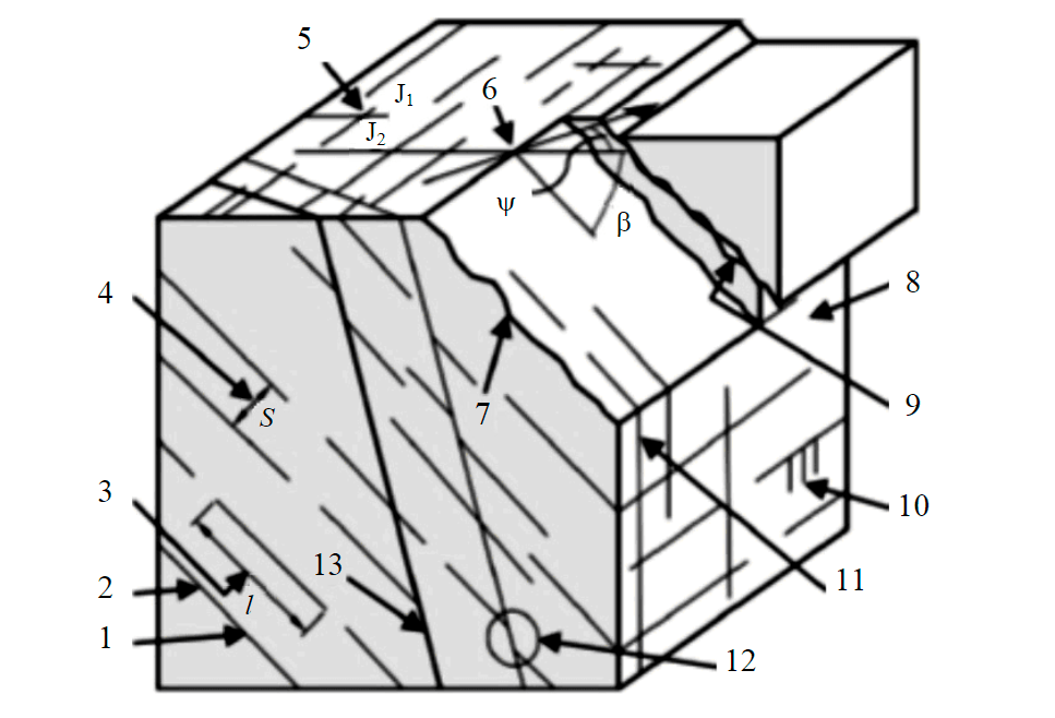
Fig.1. Parameters that characterize fractured rock mass [3, 31] 1 – rock strength on the interfaces of the fracture (Barton – Bandis criterion); 2 – weathering rate; 3 – extent; 4 – distance (interval) between fractures; 5 – fracture networks (J1, J2, …, Jn – first, second, …, nth fracture networks); 6 – spatial orientation of the fracture (β – dip angle, °; ψ – dip azimuth, °); 7 – surface texture (flat / undulating / hummocky, smooth / rough, etc.); 8 – rock type; 9 – width of fracture aperture; 10 – rate of groundwater seepage; 11 – elementary block (shape, size); 12 – groups of faults with displacement (shear) and without it; 13 – presence and material of the aggregate
Diatremes are composed of rock sequences typical for the pipes of the Yakutian diamond province: porphyry kimberlite of early generations and autolithic kimberlite breccia of the final magmatic stages. Ore bodies contain multiple large xenoliths of sedimentary rocks [1, 16].
Methodology
Structural data serve as key input values for building geological and structural models of the formations, as well as for calculating geomechanical parameters of the rock mass. Collection of these data is aimed at acquiring the most complete and comprehensive characteristic of structural disturbance, which is understood as a combination of tectonic elements, distributed in the studied rocks mass. They include faults, fracture networks, random (standalone, unsystematic) large fractures, stratification (foliation) planes. In objects with well-developed plicative processes, these elements also include folds, boudins, cleavage and several other structural forms.
In the process of in situ logging, we provided a quantitative and qualitative characteristic for all the indicated elements with obligatory estimation of their parameters (Fig.1).
We also determined numerical indicators that characterized disturbance of the rock mass: incidence of fractures in areal (number of fractures per square meter) and linear terms (number of fractures per running meter), rock quality designation (RQD). The indicated characteristics are important components of RMR and Q classifications of the rock mass [24, 28].
Structural disturbance of the rock mass was characterized in the points of geological and structural observations, located in the workings untreated with torcrete (by the time of observations) in the production levels –365, –380, –398, –425, –445, –465, –480 and –580 m TVD. Average distances between observation points were 50-200 m in the horizontal plane, 10-100 m in the vertical plane (depending on the distance between levels). In the sections with complex geological structure (near-contact zones, areas with dynamic influence of discontinuous faults, intensely fractured areas, etc.), distances between observations points were reduced to 10-20 m.
The rock mass of the deposit was divided into several domains (homogeneous units), distinguished by the specifics of structural composition and degree of destruction. We identified two large lithological domains of the first order – surrounding terrigenous–carbonate sediments and kimberlite bodies of the diatremes. These units differed in their physical and mechanical properties, specifics of geological structure, formation history and hence needed to be examined separately. Interpipe area, which formed under specific tectonic and magmatic conditions, was singled out into a separate domain. According to a widespread phreatomagmatic model [21, 26, 27], kimberlite emplacement is accompanied by a series of explosions resulting from interaction between the rising incandescent magma and cold groundwater. Phreatomagmatic explosions release great quantities of energy and by means of supersonic shock waves exert thermodynamic influence on surrounding sediments, which results in their fragmentation. Considering the presence of two adjacent diatremes in the composition of the Udachnaya pipe, as well as several stages of kimberlite magmatism [10], the interpipe rock mass will differ from the neighboring areas in terms of geological structure and overall destruction.
Obtained field data lay the foundation for a database of different-scale structural elements, developed in the rock mass in the area of pipe localization. Desk study and interpretation of obtained materials were carried out using modern software for statistical and mathematical processing and visualization of the data: Dips, Unwedge, Leapfrog, AutoCAD, STRUCTURE (proprietary design of the Tectonophysics Laboratory, Institute of Earth's Crust, SB of the RAS).
Results of geomechanical studies
Faults
Faults represent the largest structural forms, identified within the boundaries of the deposit. In the platform areas with low tectonic activity, they usually have no single main fault plain – instead they represent regions of intense mechanical and structural deformation, which contain developed sequences of second-order disjunctions: zones of increased fracturing (ZIF), brecciation (ZB) and tectonic foliation (ZTF) [4, 19]. Such zones widely occur in the rock mass of the deposit, mostly in the areas of exo- and endocontact and in the interpipe area (Fig.2)
At different levels of the Udachny quarry, we identified a total of 398 outcrops of the fault zones, which on a large scale determine block divisibility of the rock mass. An overall polar diagram of the fault zones is presented in Fig.3, a.
Analysis of the diagram shows the prevalence of steep-dipping (subvertical) faults with dipping angles exceeding 60°. They include 307 observations, which amounts to 77 % of the total number of fault zones. The diagram plotted for steeply-dipping fault zones (Fig.3, b) allows to identify four dominant directions of subvertical fault development: three of them have northeastern orientation (strike azimuths of 20-30°, 50-60°, 80-90°) and one is oriented to the northwest (strike azimuth of 300-310°). Sloping zones include 77 observations (19 % of the total number of identified fault zones); on the polar diagram they form a cone of fracturing, which contains three peaks of intensity with the coordinates 35∠50°, 116∠47°, 233∠47° (Fig.3, c). Subhorizontal (flat-lying) disturbances occur less frequently than subvertical and inclined ones (Fig.3, d). Usually they are confined to the layers of plastic rocks (clayey limestones, marls), developed in the bulk of dense carbonate sediments in the form of thin interlayers.
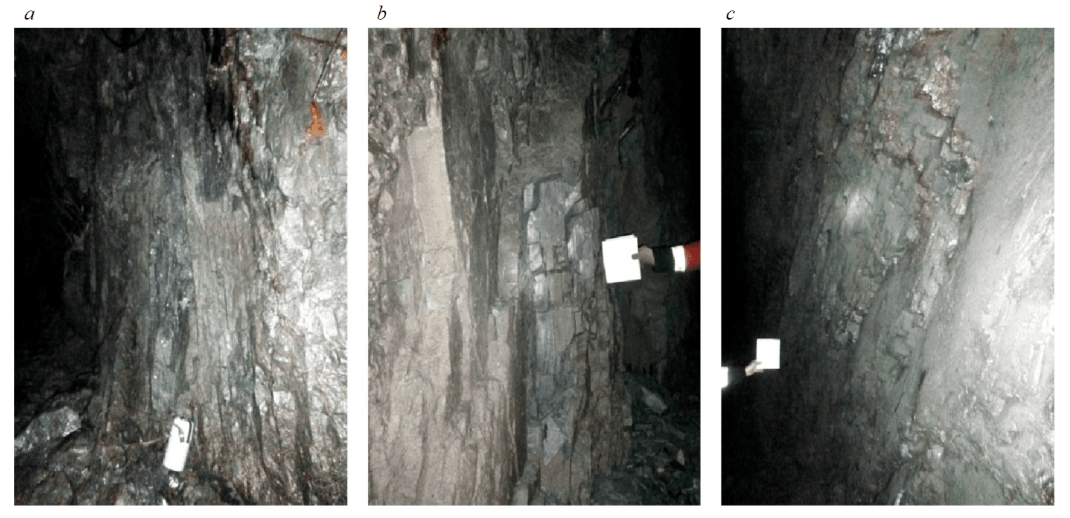
Fig.2. Outcrops of fault zones in the walls of mine workings: a – a 2 m-thick ZTF in the circular tunnel of the WOB at the level of –320 m TVD; b – a 1.2 m-thick ZIF in the circular tunnel of the WOB at the level of –320 m TVD; c – a 2.5 m-thick ZIF in the loading drive at the level of –365 m TVD
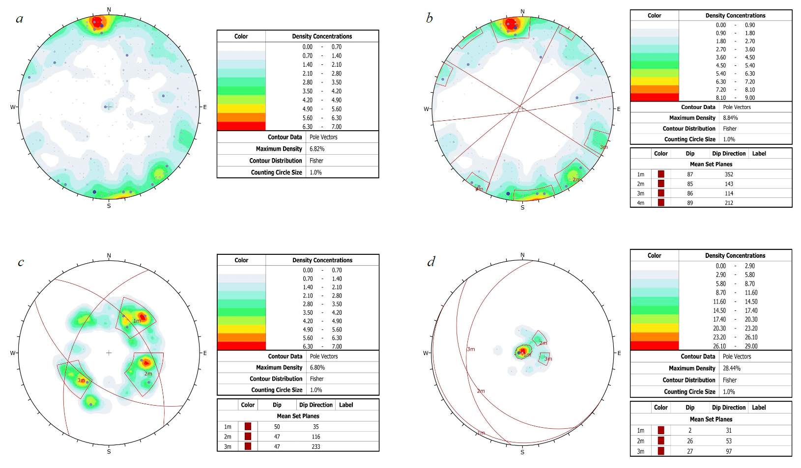
Fig.3. Polar diagrams of fault zones in the Udachny quarry: a – all observations; b – steeply-dipping faults; c – inclined faults; d – flat-lying faults
Construction of a structural model, which includes information about the largest disjunctive structures, involved tracing the faults by their outcrops in the mine workings in different areas of the deposit and determination of their spatial locations. For this purpose, a scheme was drawn, where each identified outcrop of the fault zone was visualized as a 3D disc, the orientation of which indicated the strike and the slope indicated the dip of the fault zone. The objects of mapping and tracing were axial planes of the faults. Under axial plane we understand an imaginary plane that passes through the center of the fault zone. A direct sign for drawing a fault plane was alignment of identified disturbance outcrops in the same direction along one line in the plan or in the section. Additional signs that indicated proximity of a fault zone (in the absence of directly observed outcrops of disjunctive faults) included significantly higher density of one fracture systems (compared to others) and presence of an intense peak corresponding to occurrence elements of the traced structure. As references, we used outcrops, in which the widest fault zones were observed. As a result, the following model of fault-block structure was obtained for the Udachnaya pipe localization area (Fig.4).
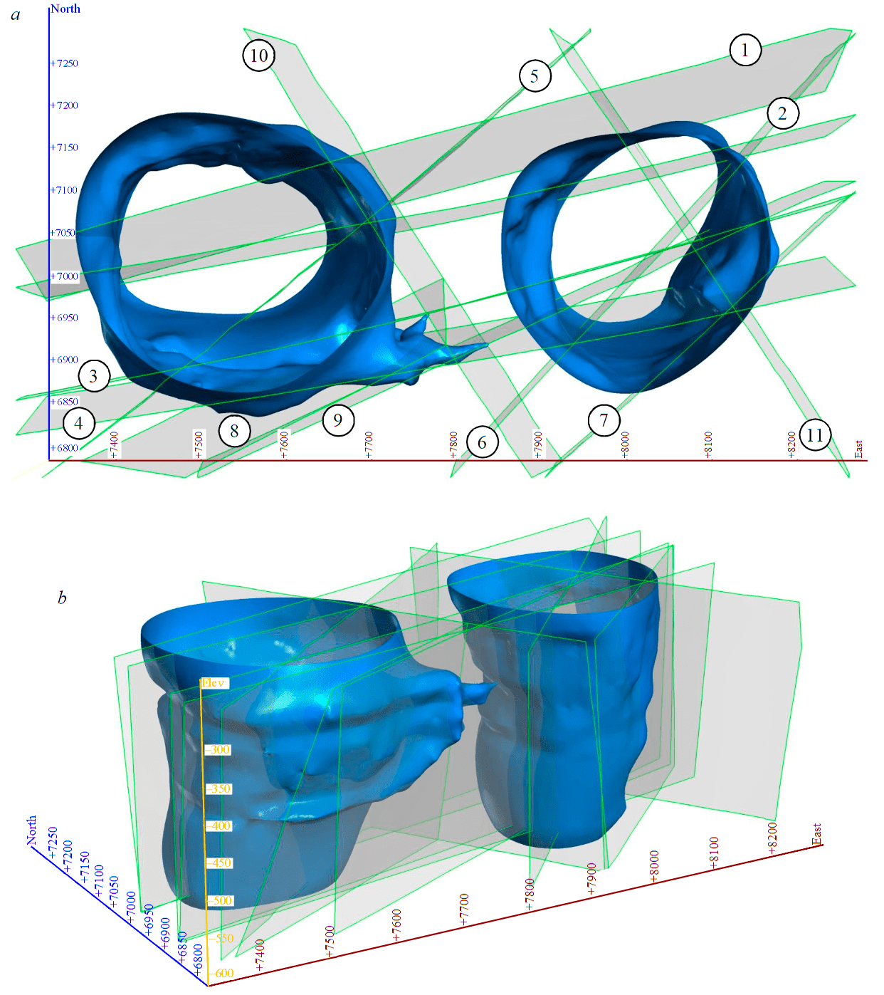
Fig.4. A model of fault-block structure of the Udachnaya pipe localization area: a – top view; b – side view 1-10 – faults
Analysis of the obtained model demonstrates that overall block divisibility of the rock mass is determined by 11 large subvertical fault zones, ranging from several tens to first hundreds of meters in width. Identified faults were traced using the outcrops in the walls of mine workings over distances more than 500 m laterally and more than 100 m in depth, crossing the boundaries of lithological varieties. The Udachnaya pipe is confined to the junction of three dominant directions of disturbance development: east-northeastern (faults 1-4), northeastern (faults 5-9) and northwestern (faults 10, 11). Localization of the pipe in the fault junction, which creates an area of increased destruction of the Earth crust, is also characteristic of other deposits in the Yakutian diamond province [12, 18, 19].
Formation and activation of the kimberlite-controlling fault structure of the Udachnaya pipe occurred in several stages with different dominant fields of tectonic stresses. The first stage was associated with activation of a thick fault zone of east-northeastern orientation (faults 1-4), which controls the sequence of pre-pipe kimberlite veins and satellite bodies of porphyry kimberlite [8, 10]. The second stage was marked by emplacement of bulk kimberlite in the fault segments of east-northeastern orientation, joined with disturbances of northwestern strike (faults 10, 11). The activation of faults with east-northeastern orientation is indicated by the presence of a large offshoot in the southeastern WOB, which is confined to the axial plane of fault 4. On the continuation of this fault in the southeastern flank of the EOB, there is an area, where the contours of the ore body change abruptly with formation of an s-shaped bend in the plan. Differences in the morphology of ore bodies on the contact with an ore-hosting fault 4 can be explained by the fact that emplacement of kimberlite bodies did not occur simultaneously – it involved at least two stages, and EOB was emplaced slightly earlier than WOB. According to the U-Pb dating of perovskites from kimberlites, the age of the eastern diatreme is 367 ± 3 and 367 ± 5 Ma, of the western one – 361 ± 4 and 353 ± 5 Ma [20]. Finally, at the third stage, against the background of current stress field alteration, segments of northwestern faults were activated, which led to emplacement of a Late Paleozoic-Early Mesozoic dolerite dike and a Cretaceous vein of potash trachyte [10].
Hence, the disjunctive structure of the deposit, reflected in the fault-block structure model (Fig.4), existed before the stage of ore body emplacement. During the period of Middle Paleozoic tectonic and magmatic activation, the peak of which fell on the Famennian stage of the Upper Devonian, individual fault segments formed areas of local extension, which were filled with kimberlite material. Since the directions of the faults identified in the model are observed within the ranges of ore bodies in their present position, it indicates the existence of later stages of fault structure activation, associated with renewal of old fault parageneses and formation of new ones [6, 7]. Many of them, especially the ones in the exo- and endocontact zone, demonstrate numerous traces of multidirectional displacements – slickensides and slickenlines. The kinematics of displacements corresponds mainly to vertical slips, less often to slips in both vertical and horizontal directions. Maximum displacement amplitudes, observed in the underground mine workings of the interpipe area, reached 1.5 m, but according to the borehole drilling data, the interpipe rock mass is characterized by a keystone structure with maximum amplitude of fault displacement about 140 m [7].
Despite a rather dense network of geological and structural observation points, second-order disturbances, which define internal structure of large fault zones, can often be traced only for the first tens of meters. Their small extent, as well as possible mutual displacements, make it difficult to accommodate faults from different hypsometric levels, which, given our current level of knowledge, does not allow to develop a unified model of secondary fault zones. Therefore, for each production level we built 3D schemes of secondary faults, where disturbances were also represented by axial planes (Fig.5).
In most cases, the extent of secondary faults is limited by larger disjunctions, included in the fault-block structure model, or by the boundaries of lithological domains. They complicate overall tectonic structure of the deposit and form block divisibility of the rock mass on a smaller scale. Undoubtedly, total number of disturbances, identified at a certain level, largely depends on the amount of mining operations and the number of mine workings available for observation. However, even current amount of information allows to draw a conclusion that in sedimentary rock areas, directions of dominant faults are characterized by higher order and continuity. For example, at the levels of –380, –425 m TVD, we registered several disjunction zones that joined series of codirectional adjacent faults. Such an order is not typical for internal sections of kimberlite bodies, where spatial distribution of secondary disturbances can be characterized as chaotic.
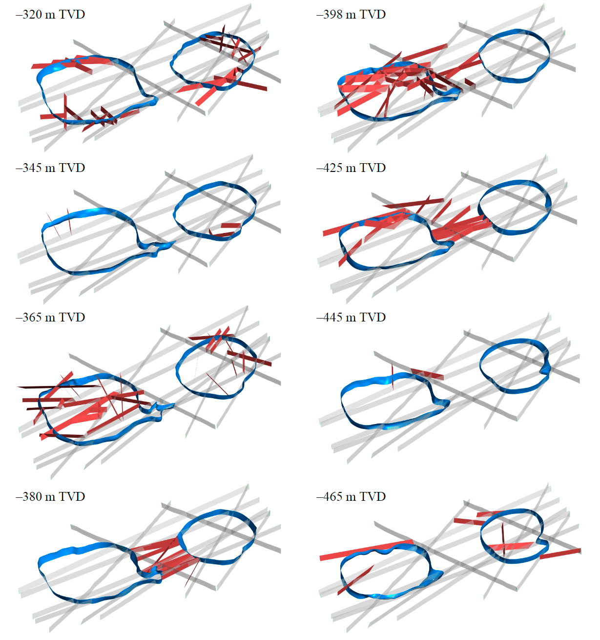
Fig.5. Location plans of main (grey) and secondary (red) faults at each level
Tectonic fracturing
Ideally, hard rock mass is a discrete material composed of rock blocks that are separated from each other by structural defects, i.e. natural defects, which have zero or low tensile strength [17]. They include faults, fracture networks, foliation planes, zones of weathered or altered rocks, etc. Dimensions and shapes of the blocks depend on spatial orientation, number and dimensional characteristics (sizes) of structural defects. Within the boundaries of large blocks, fragmentation is determined by structures of lower order – fractures and their systems, as well as foliation elements.
For each identified structural and lithological domain, we plotted a polar diagram, which displays orientation of tectonic fracturing, distributed within its boundaries (Fig.6).
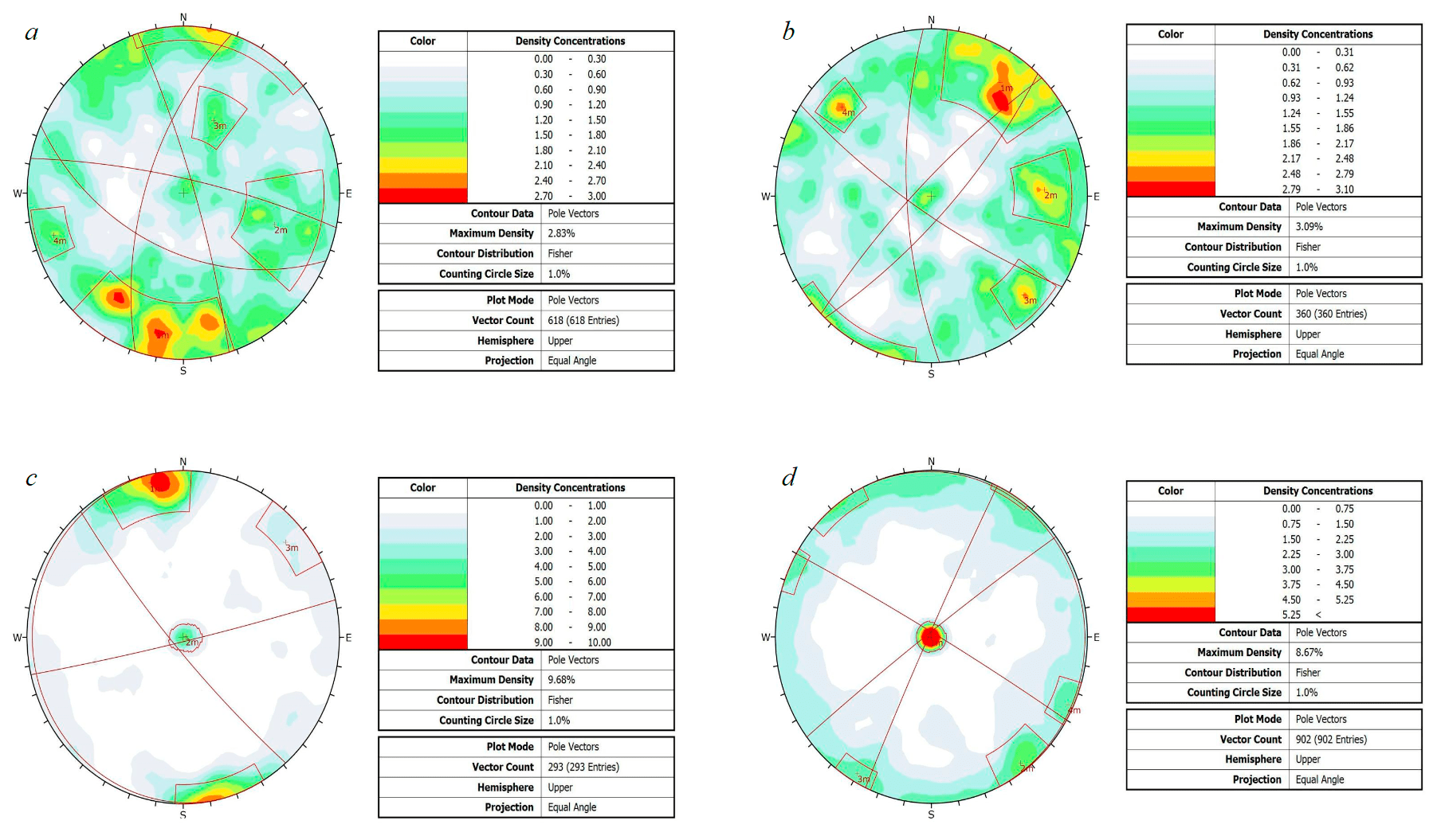
Fig.6. Polar diagrams of fracturing for identified structural and lithological domains: a – western ore body; b – eastern ore body; c – interpipe area; d – surrounding sediments
Analysis of the diagrams shows that spatial orientation and intensity of fracturing differ significantly across the domains, which confirms the correctness of their identifications as separate structural sections of the massif. The greatest differences are observed when comparing diagrams of kimberlites (Fig.6, a, b) and sedimentary rocks (Fig.6, c, d). Structural diagrams of kimberlites are characterized by the presence of multiple scattered peaks of fracture density of various intensity, which indicates that the rock mass contains many multidirectional disjunctions that split the rock mass into polyhedral blocks (Fig.6). This is explained by the fact that from the viewpoint of their structural composition, kimberlites are combined massifs that contain both foliated and non-foliated components in different proportions [9]. Such massifs are characterized by polygenic fracturing, formed by fractures of different origin. First of all, it is radial-annular (conical) fracturing, typical for intrusions of the central type. In the presented diagrams (Fig.6, a, b), radial fractures are exemplified by a series of subvertical peaks on the periphery of the diagram. Conical fractures create a cone of density isolines, formed by inclined disjunctions. In addition to that, secondary parageneses of tectonic fractures are formed in the ore bodies at the subsequent stages of tectonic activation.
Sedimentary rocks are characterized by a more concentrated distribution of fractures, mainly on the periphery of a large diagram circle, which indicates the prevalence of subvertical faults in the rock mass. Also, in each diagram there is a peak in its central part, which corresponds to flat-lying, subhorizontal fractures (diastromes), developed in stratification planes along the stratigraphic boundaries of rocks with different rheological properties [6, 8]. Such combination of fractures represents natural jointing for foliated stratified massifs.
By identifying the most intense peaks of fracturing on the diagrams, we determined the main fracture systems that form the blocky structure of the rock mass on a small scale. Data on the orientation of fracture systems in the specified structural and lithological domains are summarized in Table 1.
Table 1
Orientation of fracture systems, identified within the boundaries of structural and lithological domains of the Udachny quarry
|
Domain |
Dip azimuth/dip angle of the main fracture systems |
|||
|
WOB |
192∠80º |
108∠63º |
24∠51º |
253∠82º |
|
EOB |
135∠80º |
87∠72º |
33∠78º |
313∠76º |
|
Interpipe area |
347∠87º |
79∠2º |
49∠82º |
|
|
Surrounding rocks |
143∠87º |
246∠1º |
210∠87º |
115∠88º |
With some exceptions, the main systems form a diagonal network of fractures (northeastern-northwestern orientation), which is also characteristic of larger structural forms – faults (see Fig.4). Despite the differences in dip orientation of the systems, most of them correspond to identified directions, which is typical for both kimberlites and sedimentary strata.
To visualize quantitative indicators of structural disturbance, we built a 3D block model of fracture incidence distribution in the areal dimension N, which indicates overall destruction of the rock mass by tectonic fractures (Fig.7).
The radius of search area for modeling was set at 40 m, which allowed to take into account average distance between observation points, as well as to avoid unlimited extrapolation in the sections, where distances between points exceed search radius. Vertically, the model was limited by the marks –290 and –600 m TVD, laterally – by the contours of mine workings at the levels –320, –365, –465 m TVD. The indicated volume contained the maximum number of observation points used in the simulation. The model was built using a structural trend, which was determined based on development directions of the main faults, included in the fault-block structure model (see Fig.4). Spatial interpolation was performed using the algorithm based on radial basis function [30, 22].
Values of N parameter (number of fractures per 1 m2) for the studied rock mass varied in the range 4-20 fr./m2. Values exceeding 15 fr./m2 were excluded from the sample as outliers. They were typical for zones of intense tectonic foliation, localized in individual observation points. Remaining values were divided into three conventional intervals: 4-7 fr./m2 – low, 7-12 fr./m2 – medium, 12-15 fr./m2 – high fracture incidence.
Overall, rather heterogenous, distribution pattern of N parameter is characterized by the presence of local centers of increased values, which have linear spatial orientation. These peaks highlight the location of the main fault structures. The most contrasting point is an intense peak of east-northeastern orientation in the southeastern flank of WOB, which indicates the location of faults 4, 8 and 9 (Fig.7). Along its axial line, a large WOD offshoot can be traced; its strike is similar to that of fault 4, which suggests that the location of this offshoot was controlled by the indicated disjunctive deformation. The rest of the faults in the distribution space of fracture incidence parameter are not so clearly distinguished. There are sections, where increased N values are located in the space between several adjacent faults, for example, on the southwestern flank of WOB. Here we distinguished a block formed by faults 2, 3 and 5, in which overall fracture disturbance of the rock mass was noticeably higher than in the adjacent areas. Considering that each fault is characterized by an area of dynamic influence, i.e. an area of intense mechanical and structural deformation, sections of fault convergence are associated with superposition of these zones, which leads to an increase in overall fracture disturbance of the rock mass. A similar picture is observed in the sections of mutually intersecting faults, which occur in the central part of EOB, where a peak is formed at the junction of faults 6, 3, 9 and 11, as well as in the southeastern flank of EOB, where the maximum incidence of fractures is confined to the junction of faults 4, 7 and 11.
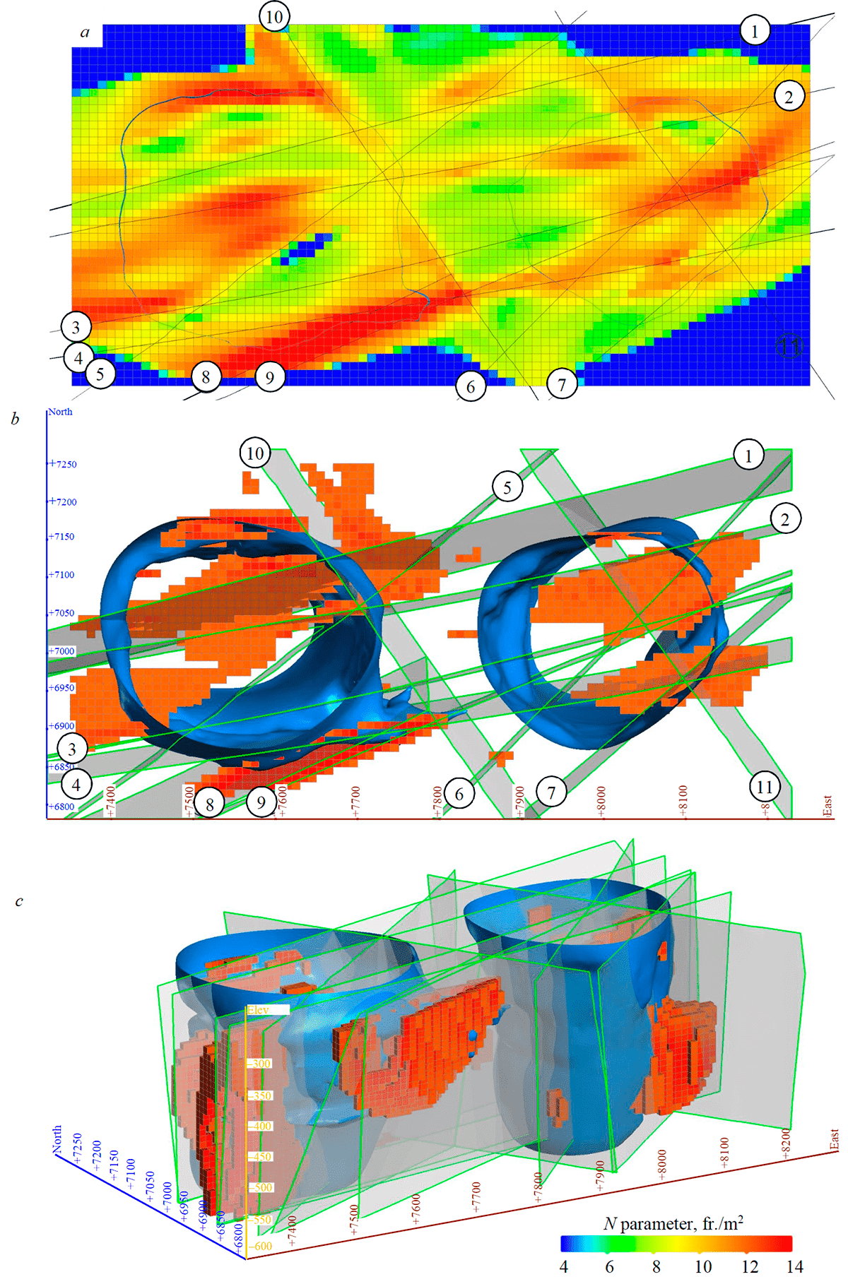
Fig.7. Block model of N parameter distribution in the near-pipe area: a – horizontal section of the model along the level –320 m TVD; b – fragments of the model with N values greater than 12 fr./m2, top view; c – view from the southwest
Location of some anomalies cannot be explained by fault structures. In most cases, they are confined to the areas of exo- and endocontact. High values of tectonic fracture incidence in the near-contact zone result from tectonic and magmatic processes that accompany pipe emplacement, as well as subsequent stages of its structural transformation. These regions contain well-developed zones of increased fracturing, as well as individual fractures with openings (breach up to several centimeters) that serve as channels for brine drainage, which results in formation of relatively large solution cavities. The maximum value of N parameter is observed in the regions with a high gradient of morphological changes in the ore bodies. These include southeastern part of WOB, where a large offshoot of east-northeastern orientation is observed, and southeastern part of EOB, where the contours of the ore body change abruptly with formation of an s-shaped bend in the plan (Fig.7, b). The section of the contour bend is located on the continuation of fault 4, along which strikes the WOB offshoot, which can indicate their common origin.
Discussion
Engineering and geological properties of a hard rock massif often have much greater dependence on the system of tectonic elements within the rock mass than on physical and mechanical properties of the rocks; similarly, quantitative indicators of fracturing are often more important than lithologies that compose the rock mass. “Despite the fact that the substance of the rock itself can be strong, or solid, or both, the system of fractures significantly weakens the rock mass and facilitates fluid conductivity” [23]. As indicated by obtained geological and structural data, rock mass of the deposit is strongly disturbed by tectonic elements of various scale. The largest of them are faults that divide the rock mass into a series of blocks of various configurations and sizes. Considering the dominant role of diagonal faults (northeastern – northwestern orientation), blocks separated by them are often shaped as a parallelepiped, less often as a rhombus or trapezium. Zones of fault influence are areas with abnormal density and deformation characteristics. Their presence leads to an increase in overall rock permeability, which entails an increased inflow of groundwater – at the deposit represented by the Middle Cambrian aquifer with strong and very strong acidic brines that contain potentially explosive homologues of methane [5, 16]. The resultant of interactions between migrating underground fluids and the drainage structure, represented by a combination of faults, fracture systems and individual fractures, is the formation of solution cavities. Most of them are located in the zones of fracture influence, both in kimberlites and in dolomites, as well as along the periphery of the ore bodies. From the position of geomechanical state of the rock mass, these structures are not critical for its stability, but they can act as accumulators of fluids, including gas-saturated ones.
Structural forms of smaller scale – fractures and fracture systems – form elementary block structure of the rock mass that is responsible for its fragmentation and stability. The size of elementary block is one of the main input parameters in the calculation of average particle size of the broken rock mass. For the most part, blasting splits the rock mass into natural blocks bounded by existing fractures. Numerous studies have established that “greater intensity of rock fracturing and, consequently, smaller size of the elementary block translate into better rock fragmentation by the blast, more sparse blasthole grid and lower powder factor for obtaining required granulometric composition of the rock mass” [9]. Therefore, estimation of this parameter and determination of specific characteristics of its variability in the volume of the rock mass represent important steps in the design of rational drilling and blasting parameters for large-scale blasts. Judging by average values, WOB is characterized by significantly larger elementary blocks (Table 2).
According to the existing classification, WOB blocks are considered large in terms of their volume [29]. In other domains, we obtained approximately equal values of block volumes ranging in the interval 0.07-1.11 m3, which can be classified as medium blocks.
Table 2
Average quantitative indicators of fracturing across the domains
|
Domain |
Number of measurements |
Percentage of the total number of measurements |
Average distance between fractures in the rock mass, m |
Elementary block volume, m3 |
Fracture incidence per unit of volume, fr./m3 |
|
Surrounding rocks |
100 |
50.76 |
0.1177 |
0.107863 |
12.3125 |
|
EOB |
24 |
12.18 |
0.120833 |
0.069253 |
11.54708 |
|
WOB |
44 |
22.34 |
0.190909 |
0.352318 |
9.120455 |
|
Interpipe area |
29 |
14.72 |
0.127586 |
0.084834 |
11.11966 |
Despite significant differences in the block volume of kimberlites, within the ranges of WOB and EOB we observed heterogeneous fragmentation of the rock mass into elementary blocks. There are regions with developed systems of sparse fractures and individual large fractures that split the kimberlite mass into large blocks (up to 2-3 m across). At the same time, these blocks, separated by fractures, are relatively monolithic, i.e. slightly disturbed by hidden tectonic fractures of smaller scale. Such sections are characterized by high RQD indicators that reach up to 90-95 %. Under standard parameters of drilling and blasting operations, these sections of slight fracture disturbance act as the main source of oversize.
From the position of geomechanical state, other conditions being equal (resistance to shear along the fracture, roughness, undulation, continuity, mineral aggregate filling), massifs with large average size of elementary blocks are characterized by greater stability compared to massifs composed of small blocks. It should be noted that this statement holds true only when the size of the elementary block is smaller than the size of the working, which defines the possibility of caving. Taken in general, friction properties of fracture structures have average values for such type of deposits. Kimberlites are dominated by moderately undulating fractures with a smooth and slightly rough surface. Fractures located in the surrounding sediments are characterized by straighter and smoother surfaces, which is explained by a widespread development of subhorizontal diastromes. Despite the fact that kimberlites are easily weathered rocks [11], the walls of fractures are fresh, less often faintly weathered, which agrees with the overall degree of weathering in the massif within the rock blocks.
The largest fracture planes are located on the periphery of the ore bodies, directly on the contact between kimberlite and surrounding sediments. Considering subvertical nature of the contact and minimal shear strength of slickensides, these sections of the rock mass are characterized by reduced stability.
The majority of system fractures, both in kimberlite and in surrounding sediments, are closed, with a breach up to several millimeters. For large random individual fractures, the width of the aperture can reach several centimeters. They are usually located in the interpipe area, where they facilitate a massive influx of water in the form of outflow or intense seepage. A mineral aggregate that partially fills the fractures in kimberlite is represented by products of secondary mineralization – calcite, barite, quartz in association with sulfides – pyrite, marcasite. The thickness of the aggregate does not exceed first centimeters, which does not restrict any motion along the fracture and exerts no significant effect on overall stability of the rock mass.
In addition to already mentioned features, negative factors that reduce friction properties of fracture structures include oil and bitumen shows, widespread in the rock mass of the deposit and mostly concentrated in the surrounding rocks. The presence of sections with abundant hydrocarbon shows negatively affects the state of the rock mass. Oil and bitumen possess high lubricating properties and significantly reduce adhesion (shear strength) of the structural blocks, which can increase their cavability potential.
Conclusions
To sum it up, performed studies were aimed at providing a quantitative and qualitative characteristic of different-scale structural elements, developed in the rock and ore mass of the deposit. It was established that larger elements – faults – form a kimberlite-containing junction, composed of disjunctions that have three directions of development: east-northeastern, northeastern and northwestern. Faults do not have a single fault plain, instead they represent regions of increased fracturing, brecciation and tectonic foliation and differ from other sections of the rock mass by significantly elevated destruction of the substrate. Within the boundaries of four structural and lithological domains, we identified dominant systems of tectonic fractures, estimated key quantitative indicators of structural disturbance of the rock mass and built a 3D distribution model of N parameter, which reflects overall destruction of the rock mass by tectonic fractures. Combined use of obtained geological and structural characteristics with geological, hydrogeological and mining engineering data will allow to develop the deposit, while maintaining a balance between efficiency and safety of performed operations. Undoubtedly, these data may not be enough for confident forecasting of structural disturbance and geomechanical state of the rock mass in deeper levels of the mine. To solve this problem, it is necessary to continue studies on fracturing/disturbance as the mine becomes deeper and to utilize large amounts of data obtained by advance exploration.
References
- Kostrovitskii S.I., Spetsius Z.V., Yakovlev D.A. et al. Atlas of Primary Diamond Deposits of the Yakutian Diamond Province. Mirnyi: ALROSA, 2015, p. 480 (in Russian).
- Borshch-Komponiets V.I. Practical Rock Mechanics. Мoscow: Gornaya kniga, 2013, p. 322 (in Russian).
- Bushkov V.K. Use of kinematic stability analysis in substantiation of basic wall design parameters for open pits. Gornyi informatsionno-analiticheskii byulleten. 2018. N 10, p. 30-42. DOI: 10.25018/0236-1493-2018-10-0-30-42 (in Russian).
- Seminskii K.Zh., Gladkov A.S., Lunina O.V., Tugarina M.A. Internal Structure of Continental Fault Zones. Practical Aspect. Novosibirsk: Izd-vo Sibirskogo otdeleniya RAN, Filial “Geo”, 2005, p. 291 (in Russian).
- Drozdov A.V. Mining-and-Geological and Engineering Problems in Construction of Underground Mine Udachny. Gornyi informatsionno-analiticheskii byulleten. 2015. N 2, p. 125-131 (in Russian).
- Drozdov A.V. Mining-and-Geological and Engineering Problems in Construction of Udachny Underground Mine. Gornyi informatsionno-analiticheskii byulleten. 2011. N 3, p. 153-165 (in Russian).
- Drozdov A.V., Melnikov A.I. Structural Specifics of Multi-Phase Kimberlite Pipes (Exemplified by the Udachnaya Pipe). Marksheideriya i nedropolzovanie. 2009. N 1, p. 31-38 (in Russian).
- Drozdov A.V., Melnikov A.I., Boki I.B. Estimation of structure and tectonics of Udachnaya mine for deeper level mining. Fundamentalnye i prikladnye voprosy gornykh nauk. 2014. Vol. 1. N 1, p. 91-97 (in Russian).
- Dunaev V.A., Ermolov V.A. Geological Factors Affecting Blastability of the Rocks in Open-Pit Mining. Gornyi informatsionno-analiticheskii byulleten. 1999. N 1, p. 11-16 (in Russian).
- Egorov K.N., Melnikov A.I. Structural and Compositional Evolution of Kimberlite Body System of the Udachnaya Pipe. Rudy i metally. 2013. N 1, p. 53-59 (in Russian).
- Zakharov E.V. Decreasing Energy of Rock Destruction as a Result of Frost Weathering. Gornyi informatsionno-analiticheskii byulleten. 2013. N 4, p. 157-165 (in Russian).
- Ignatov P.A., Bushkov K.Yu., Tolstov A.V., Yanygin Yu.T. Mapping of Hidden Displasements of Kimberlite-Controlling Structures in Nakyn Kimberlite Field. Problemy prognozirovaniya i poiskov mestorozhdenii almazov na zakrytykh territoriyakh, 18-20 marta, 2008, Mirnyi, Rossiya. Yakutsk: Izd-vo Yakutskogo nauchnogo tsentra SO RAN, 2008, p. 325-331 (in Russian).
- Kolganov V.F., Akishev A.N. Mining and Geological Specifics of Developing Primary Diamond Deposits in Yakutia. Mirnyi: Mirninskaya gorodskaya tipografiya, 2013, p. 568 (in Russian).
- Latyshev O.G., Kazak O.O. The influence of the geological material disturbance on its properties and condition. Izvestiya Uralskogo gosudarstvennogo gornogo universiteta. 2017. Vol. 4 (48), p. 62-65. DOI: 10.21440/2307-2091-2017-4-62-65 (in Russian).
- Sklyarov E.V., Alekseev S.V., Egorov K.N. et al. Specifics of Developing Primary Diamond Deposits under Difficult Mining and Geological Conditions in the Eastern Sector of the Arctic. Fundamentalnye issledovaniya Prezidiuma RAN. 2015. URL: http://www.ras.ru/FStorage/FileInfo.aspx?catalogId=bc1f245b-9bf7-419c-b15c-292b9c4bf031&id=42ea960d-52f1-4259-886a-eda0e6bcac6e (date of access 21.01.2021).
- Alekseev S.V., Alekseeva L.P., Gladkov A.S. et al. Brines in deep horizons of the Udachnaya kimberlite pipe. Geodinamika i tektonofizika. 2018. Vol. 9. N 4, p. 1235-1253. DOI: 10.5800/GT-2018-9-4-0393 (in Russian).
- Guidelines for Open Pit Slope Design. Ed. by D.Rid, P.Steisi. Ekaterinburg: Pravoved: Polimetall, 2015, p. 527 (in Russian).
- Serebryakov E.V., Gladkov A.S., Koshkarev D.A. Three‐dimensional structural‐material models of the formation of the Nyurbinskaya and Botuobinskaya kimberlite pipes (Yakutian diamondiferous province, Russia). Geodinamika i tektonofizika. 2019. Vol. 10. N 4, p. 899-920. DOI: 10.5800/GT-2019-10-4-0448 (in Russian).
- Gladkov A.S., Bornyakov S.A., Manakov A.V., Matrosov V.A. Tectonophysical Studies during Diamond Prospecting. Мoscow: Nauchnyi mir. 2008, p. 175 (in Russian).
- Ragozin A.L., Zedgenizov D.A., Shatskii V.S. et al. U-PB age of rutile from the eclogite xenolith of the Udachnaya kimberlite pipe. Doklady Akademii nauk. 2014. Vol. 457. N 1, p. 861-864. DOI: 10.1134/S1028334X14070162
- Porritt L.A., Russell J.K., McLean H. et al. A Phreatomagmatic Kimberlite: The A418 Kimberlite Pipe, Northwest Territories, Canada. Proceedings of 10th International Kimberlite Conference. New Delhi, Springer, 2013. Vol. 2, p. 97-108. DOI: 10.1007/978-81-322-1173-0_7
- Comparing Leapfrog Radial Basis Function and Kriging. Seequent. May 19, 2000. URL: https://www.seequent.com/comparing-leapfrog-radial-basis-function-and-kriging (date of access 21.01.2021).
- Goodman R.E. Engineering geology. Rock in engineering construction. John Wiley & Sons. New York, 1993, p. 432.
- Hoek E., Brown E.T. The Hoek-Brown failure criterion and GSI – 2018 edition. Journal of Rock Mechanics and Geotechnical Engineering. 2018. Vol. 11. Iss. 3, p. 445-463. DOI: 10.1016/j.jrmge.2018.08.001
- Jakubec J. Role of defects in rock mass classification. Proceedings of the Seventh International Symposium on Ground Support in Mining and Underground Construction, 13-15 May, 2013, Perth, Australia. Australian Centre for Geomechanics, 2013, p. 337-344. DOI: 10.36487/ACG_rep/1304_21_Jakubec
- Kurszlaukis S., Lorenz V. Formation of “Tuffisitic Kimberlites” by phreatomagmatic processes. Journal of Volcanology and Geothermal Research. 2008. Vol. 174. Iss. 1-3, p. 68-80. DOI: 10.1016/j.jvolgeores.2007.12.047
- Lorenz V., Kurszlaukis S. Root zone processes in the phreatomagmatic pipe emplacement model and consequences for the evolution of maar-diatreme volcanoes. Journal of Volcanology and Geothermal Research. 2007. Vol. 159. Iss. 1-3, p. 4-32. DOI: 10.1016/j.jvolgeores.2006.06.019
- Palmstrom A. Combining the RMR, Q, and RMi classification systems. Tunnelling and Underground Space Technology. 2009. Vol. 24. Iss. 4, p. 491-492. DOI: 10.1016/j.tust.2008.12.002
- Palmstrom A. Measurements of and Correlations between Block Size and Rock Quality Designation (RQD). Tunnelling and Underground Space Technology. 2005. Vol. 20. Iss. 4, p. 362-377. DOI: 10.1016/j.tust.2005.01.005
- Alcaraz S., Lane R., Spragg K. et al. 3-D geological modelling using new Leapfrog Geothermal software. Proceedings Thirty-Sixth Workshop on Geothermal Reservoir Engineering 31 January – 2 February, 2011, Stanford, California, USA. Stanford University, 2011. Vol. 31, p. 1-6.
- Wyllie D.C. Foundations on Rock: 2nd edition. London, Taylor and Francis, 1999, p. 401.