
Autoclave modeling of corrosion processes occurring in a gas pipeline during transportation of an unprepared multiphase medium containing CO2
- 1 — Deputy Director of the Scientific and Technological Complex Saint Petersburg Polytechnic University of Peter the Great ▪ Orcid
- 2 — Ph.D. Leading Engineer Saint Petersburg Polytechnic University of Peter the Great ▪ Orcid
- 3 — Tutor Saint Petersburg Polytechnic University of Peter the Great ▪ Orcid
- 4 — Engineer Saint Petersburg Polytechnic University of Peter the Great ▪ Orcid
- 5 — Ph.D., Dr.Sci. Head of Department Engineering company OOO “IT-Service” ▪ Orcid
- 6 — Deputy General Director Engineering company OOO “IT-Service” ▪ Orcid

Abstract
The problem of selecting a method for ensuring the reliability of the unprepared fluid transport facilities of an unprepared fluid in the presence of carbon dioxide is considered. Carbon dioxide corrosion is one of the dangerous types of damage to field and main pipelines. It has been shown that dynamic autoclave tests should be carried out during staged laboratory tests in order to determine the intensity of carbon dioxide corrosion and to select the optimal method of protection. A hypothesis about the imperfection of the existing generally accepted approaches to dynamic corrosion testing has been put forward and confirmed. A test procedure based on the use of an autoclave with an overhead stirrer, developed using elements of mathematical modeling, is proposed. The flows created in the autoclave provide corrosive wear of the sample surface similar to the internal surfaces elements wear of the pipelines piping of gas condensate wells. The autoclave makes it possible to simulate the effect of the organic phase on the flow rate and the nature of corrosion damage to the metal surface, as well as the effect of the stirrer rotation speed and, accordingly, the shear stress of the cross section on the corrosion rate in the presence/absence of a corrosion inhibitor. The given results of staged tests make it possible to judge the high efficiency of the developed test procedure.
None
Introduction
At present, the gas industry is of strategic importance for the development of the Russian economy [1]. The largest source of state budget replenishment (about 50 %) – natural gas – plays a huge role in the life support of the population [2], acting as the most important structural component of the development productive forces of the country [3] and its regions [4, 5].
The Unified Gas Supply System (UGSS) is a key infrastructure of the Russian economy, an extensive network of main pipelines that unites 66 constituent regions of the Russian Federation, providing over 60 % of the energy resources demand. The share of Russian gas in European consumption reaches 35-40 %, according to Gazprom.
Russian Federation UGSS operation effectiveness largely depends on the reliable operation of field pipelines, as well as their integrated safety and reduction of possible damage as a result of emergency situations. According to the analysis of statistical data on the accident rate of field and main pipelines for the transport of raw gas, one of the main causes of failures is damage caused by carbon dioxide corrosion [6].
Carbon dioxide (CO2, carbon dioxide, carbonic anhydride) as a corrosive component of the environment in the gas production process was previously assigned a small role compared to hydrogen sulfide (H2S) [7-9]. The problem of carbon dioxide corrosion has become increasingly important with the start of development of deep gas condensate fields with reservoir temperatures over 80 °С, pressures over 30 MPa and CO2 content in gas over 1 vol. % [10-12].
The carbon dioxide corrosion mechanism has been sufficiently studied and generally consists of the following stages: active dissolution of the metal with the formation of a discontinuous corrosion products layer; local, caused by physical (abrasive action of particles contained in the flow, hydraulic action of the flow) or chemical factors, removal of a corrosion products film from the metal surface of the defective areas [13, 14]; transformation of these areas into active anodes, which contribute to the local corrosion occurrence with the initiation of pitting, ulcers and, as a result, mesa corrosion [15-17].
Various researchers [18-20] indicate the main factors affecting the intensity of CO2 corrosion: temperature; the presence of an aqueous phase in which CO2 will dissolve; flow rate; water mineralization; pH [7].
To ensure the field pipelines reliability for the untreated gas transport, to reduce the CO2 corrosion rate to an acceptable level in accordance with the Gazprom RD (0.1 mm/year), various protection methods are used based on the use of new materials for the construction of gas transmission infrastructure, inhibitor protection, optimal modes of equipment operation, etc. [22-24]. To select the most effective method,
calculation and (or) laboratory methods, according to approved methods, are used [25, 26].
One of the methods for predicting carbon dioxide corrosion and evaluating the effectiveness of methods of protection against it, is static laboratory tests in Drexel cells in an aqueous medium in the presence of CO2. Tests are carried out according to the recommendations of GOST R 9.905-2007, GOST R 9.908-85 using the gravimetric method for assessing the corrosion rate [27-29]. A significant disadvantage of this approach is that it does not take into account the influence of the hydrodynamics of the gas-liquid flow on the corrosion process [30]. The predicted corrosion rates obtained with its help correspond to the observed ones only if the metal is in constant contact with the aqueous phase, and the flow velocity is low. Obviously, this condition is not always satisfied for wells and pipelines [31]. Due to the fact that the flow regime of the gas-liquid mixture significantly affects the rate of carbon dioxide corrosion, which is confirmed by numerous studies [32-34], this must be taken into account when conducting laboratory tests to predict carbon dioxide corrosion.
There are well-known approaches for assessing the rate of carbon dioxide corrosion under dynamic conditions when exposed to a two-phase liquid medium in the presence of CO2 [35]. The tests are carried out on a plant with constant mixing of a water-hydrocarbon working medium, simulating watered gas condensate at atmospheric pressure and varying temperature. The main disadvantage of this approach is that it does not take into account the partial pressure of carbon dioxide, which significantly affects the intensity of the corrosion process.
The most accurately reproducing the conditions of corrosion processes in the pipeline that occur during the transport of a multiphase medium with carbon dioxide is the method of modeling field conditions in an autoclave complex (RCA) [36, 37]. OS (organization standard) Gazprom 9.3-007-2010 “Method of laboratory testing of corrosion inhibitors for equipment for production, transportation and processing of corrosive gas” is based on the determination of tangential stresses (TNnS) on the surface of the sample from the action of the flow, leading under certain hydrodynamic conditions to the intensification of corrosion processes. It has been established that high values of TNnS on the pipe inner surface lead to the continuous removal of corrosion products (carbonate deposits), thereby exposing the “fresh” metal surface to the environment, which leads to an increase in the local corrosion rate.
RCA-type devices are a type of apparatus with a stirrer, where samples of the test material are fixed on a rotating holder (cage). There is currently no standard, universally accepted RCA design. [38]. However, a fairly large number of modifications are known [39-41], which create certain difficulties in comparing and interpreting data obtained in different laboratories.
Carried out in work [26] studies of the operation efficiency of several most common types of RCA using numerical simulation methods with subsequent validation of the results on a bench autoclave complex showed an asymmetry of the flow distribution inside the autoclave, leading to uneven wear of the sample surface.
An analysis of the obtained results leads to the conclusion that the corrosion rate tests using rotary cage autoclaves (RCA) are very sensitive to the design. Since the uneven surface wear of the samples does not correspond to the pipelines material actual degradation picture, gas transmission infrastructure facilities, it is incorrect to carry out a quantitative interpretation of the results of such tests when predicting the corrosion rate. The purpose of this work is to develop an autoclave design that provides a uniform distribution of TNnS over the sample surface during research and to conduct a series of tests to confirm the hypothesis about the imperfection of the existing generally accepted approaches to dynamic testing.
Methodology and research methods
Stirred autoclave design
Since classical design, taking into account the whole variety of embedded parameters, is very laborious and expensive, and the need to create a methodology for setting up experiments that ensures the convergence of the results obtained with real field conditions requires a large number of calculations, numerical simulation methods (CFD) modeling in the ANSYS software package were used.
The first stage of autoclave modeling was the development of options for the technical implementation of its design. Since the main disadvantage of the known device with a rotating cage is the uneven distribution of the flow over the surface of the sample, it was decided in the new design to fix the samples motionlessly against the walls of the autoclave, and the flow to be created by an impeller rotating in the center.
Mathematical modeling was carried out on a simplified (parametric) model of an autoclave with samples and a stirrer with a constant rotation speed (2000 rpm) in a given computational region. The parametric model consists of an outer cylinder that mimics the body of an autoclave; witness samples (plates) located along the generatrix along the walls of the autoclave body; internal cylinder simulating the blades of the stirrer.
The shape of the autoclave is such that a periodicity condition can be included in its parametric model, which makes it possible to divide the model into several sectors and perform the calculation for only one of them. Such a simplification can significantly reduce the computational complexity of the model.
Since the number of samples determines the autoclave structure geometry and the nature of the flow distribution over the surface of the samples, the task of mathematical modeling was to establish the relationship between these factors.
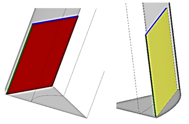
Fig.1. Witness sample: front plane highlighted in red, rear plane in yellow, side faces in green, top face in blue
During the simulation, we varied the geometric dimensions of the samples, their number, as well as the distance between the samples surface and the stirrer blades. At the same time, the values of shear stresses (characterizing the uniformity of the flow distribution over the sample) on the four faces of the witness sample (side, front, top) were monitored – both maximum and average values (Fig.1).
Corrosion test procedure
The described autoclave was used to evaluate the influence of the hydrodynamics of the flow of a corrosive medium and its phase composition on the rate and nature of CO2 corrosion. A number of experiments have been carried out:
- Process temperature – 105 °С, overpressure 6 MPa. As a model medium, a gas-liquid hydrocarbon mixture was used: the gas phase N2 + CO2 in a ratio that provides a partial pressure of carbon dioxide of 0.2 MPa; kerosene was used as the organic phase; water phase – water with a mineralization of 4.75 g/l. The ratio of the liquid phase to the gaseous 90:10 vol. %. The rotation frequency of the impeller was 750 rpm, the duration of the tests was 15 days. In this experiment, the corrosion of liners of gas-condensate wells was modeled in the case of the appearance of a free aqueous phase at the bottomhole.
- Process temperature 42-46 °С, overpressure 6 MPa. As a model medium, a gas-liquid mixture was used: the gas phase N2 + CO2 in a ratio that provides a partial pressure of carbon dioxide of 0.2 MPa; water phase – water with a mineralization of 4.75 g/l. The ratio of the liquid phase to the gaseous 90:10 vol. %. The used concentration of the corrosion inhibitor “Soncor 9020” was 100 mg/l. The rotation frequency of the impeller is 150-670 rpm, the test duration is 24-360 h. In this case, the influence of the degree of closing of the angular throttle of the gas condensate well X-mas tree, and hence the speed and direction of the flow of the transported medium, on the rate of CO2 corrosion of the inner surface of pipelines was simulated strapping in the presence/absence of a corrosion inhibitor.
To assess the corrosion rates, witness samples – plates 30 x 50 x 5 mm made of steel 09G2S – after being removed from the autoclave were cleaned, degreased and weighed on a balance with an accuracy class of 0.0001 g. Cleaning was carried out according to GOST 9.907-2007. Corrosion rate was determined by weight loss and recalculated in mm/year.
Results discussion
Autoclave numerical simulation results
The results (Table 1) showed that the more samples are used in its design, the smaller the ratio between the maximum and average values of shear stresses, which indicates a less uneven flow distribution. Thus, in order to create a uniform picture of the distribution of TNnS (Fig.2) over the surface of the sample and, accordingly, to obtain uniform corrosion wear, it is necessary to position the samples in such a way that the difference in distances between the witness sample and the autoclave body is minimal. Table 1 shows the ratios of the maximum value of TNnS to the average, which show that the higher this value, the greater the inhomogeneity of the flow distribution over the surface of the sample and, accordingly, the higher the likelihood of uneven wetting of its surface and corrosive wear.
Table 1
Autoclave numerical simulation results
|
Number |
TNnS ratio |
|||
|
Left side edge |
Right side edge |
Upper end |
Front plane |
|
|
12 |
4.064 |
8.379 |
1.533 |
9.212 |
|
9 |
11.428 |
9.659 |
1.796 |
15.083 |
|
6 |
9.963 |
23.041 |
1.785 |
30.492 |
Based on the calculation results, the following additional conclusions can be drawn:
- Since the structure of the flow formed in the autoclave, in addition to the rotation speed, is significantly affected by the geometric parameters of the witness sample (size, distances between the coupons and the stirrer), they must be controlled, having previously indicated the correlations between the specified conditions and the predicted results of corrosion wear;
- In the design of the autoclave, the witness samples must be positioned in such a way that the gap between them is minimal and isolated from the effects of the flow. Since mathematical modeling predicts the occurrence of high values of TNnS at the ends of individual samples, this can lead to increased wear of surfaces that are not important from the point of view of assessing the intensity of corrosion wear.
In addition to the geometric parameters of the autoclave, when designing, it is necessary to set the boundary technical conditions: operating temperature ≤ 150 °C, operating pressure 10 MPa, flow velocity 1-10 m/s.
In addition to the autoclave 1, the test setup (Fig.3) includes a magnetic clutch 2, a V-belt drive 3 and an electric motor 4. The main advantage of this design is simplicity and versatility. The use of a V-belt transmission allows you to select the desired rotation speed by changing the gear ratio, for which it is enough to replace the pulley. The electric motor with a frequency regulator provides the necessary rotation speed throughout the test. The use of an electromagnetic clutch solves the problem of sealing moving parts with a large pressure drop.
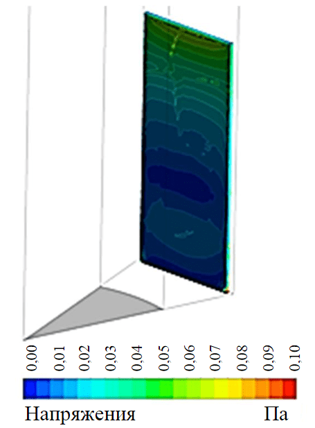
Fig.2. Distribution of shear stresses over the surface sample
The design of the autoclave is shown in Fig.4. The rotational moment from the electric motor is transmitted through the magnetic coupling 4 inside the autoclave, to the shaft 5. The flow movement in the autoclave is created by communicating the rotational movement of the liquid with the impeller 6. Nine samples 1 are fixed in the drum 7, they are on the same level with the impeller. To reduce losses and increase the service life, the shaft is fixed in plain bearings 3, 8. Three fittings 2 are provided for the inlet and outlet of gases.
To obtain various shear stresses created by the medium on the surface of the sample, it is possible to change the distance between the samples and the impeller, which allows you to get as close as possible to real conditions. The designed autoclave for dynamic corrosion testing is shown in Fig.5.
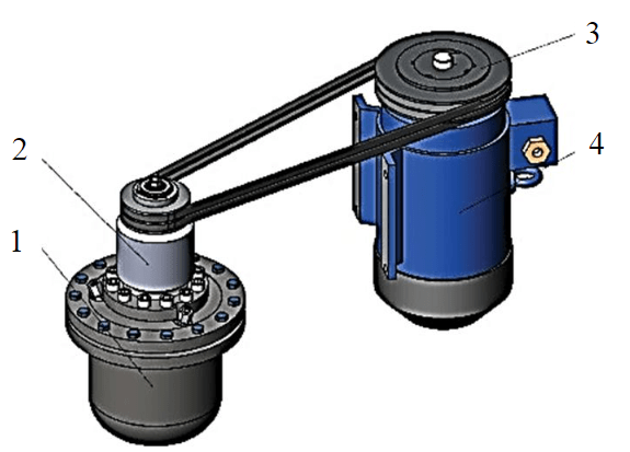
Fig.3. General view of the test setup
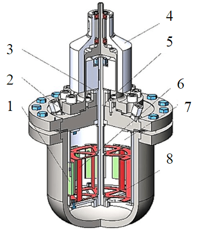
Fig.4. Autoclave
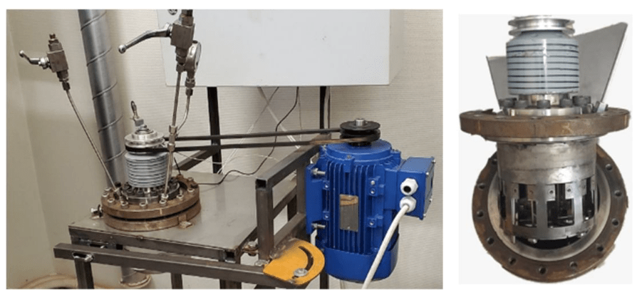
Fig.5. Autoclave for dynamic corrosion testing
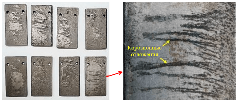
Fig.6. Samples after autoclave testing
Results of corrosion tests and their analysis
The appearance of the samples after testing is shown in Fig.6. The average corrosion rate according to the test results was 0.011 mm/year. The corrosion products formed on the surface of the samples are unevenly distributed, mainly in the form of strips elongated in the direction of flow. The phase composition of the surface, determined on an X-ray diffractometer, showed the presence of FeCO3, the main product of carbon dioxide corrosion. Figure 7, a shows a photograph of the surface with corrosion products, made on a scanning electron microscope. Deposits have a crystal structure characteristic of CO2 corrosion. X-ray microanalysis confirmed the presence of Fe, C and O in a stoichiometric ratio comparable to the found phase. Figure 7, b shows the cross section of the sample after autoclave testing. It can be seen that corrosion products are formed not only on the surface in the form of crystals, but also penetrate into the base metal of the sample, forming small pits.
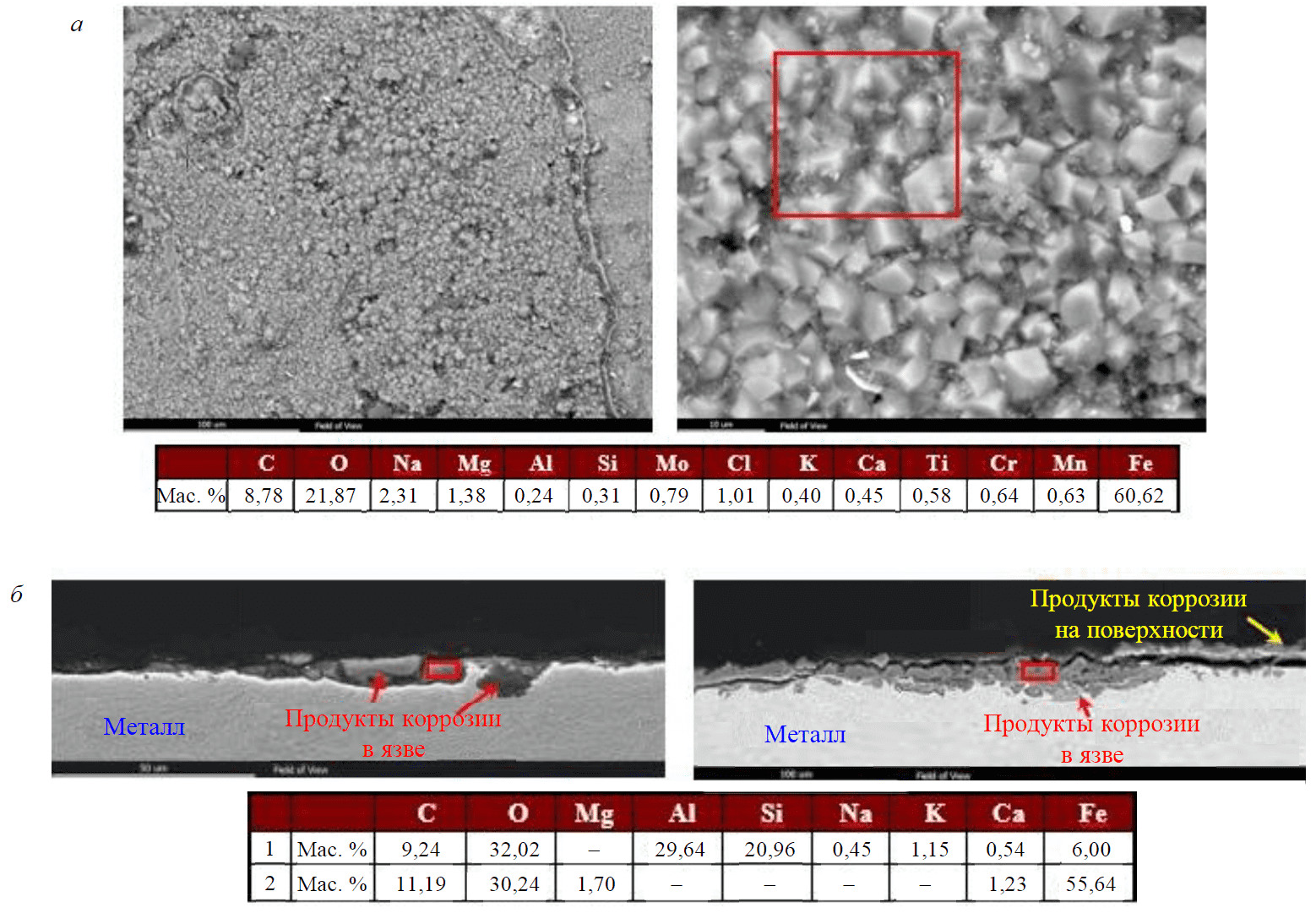
Fig.7. Surface (a) and section (b) of a sample with corrosion products after autoclave tests (electron microscopy)
The profile of corrosion damage on the samples surface can be compared with the graph of the distribution of TNnS (see Fig.2). Corrosion damaged samples show a symmetrical damage profile similar to the shear stress profile predicted by CFD modeling.
According to the results of hydrodynamic calculations, the maximum (at the point) value of TNnS is observed at a distance of 200 mm from the corner throttle (CT), which is open by 7.4 % and amounts to 16.69 Pa. The flow equalization and stabilization of the TNnS at the level of 8 Pa occur at a distance from the CT greater than 600 mm. In the case of a fully open throttle, the TNnS is 2 Pa.
Based on the obtained values of TNnS, a number of experiments were carried out, the generalized results are shown in Table 2.
The patterns revealed in the course of autoclave tests are consistent with the generally recognized laws for describing the mechanism of carbon dioxide corrosion: at the beginning of the process, active dissolution of the metal occurs – the corrosion rate is maximum (usually the process takes several days). Then a non-continuous layer of corrosion products (iron carbonates) is formed, which acts as a protective film – the corrosion rate slows down. With an increase in the flow rate, the layer of corrosion products is washed away – the corrosion rate increases.
High values of shear stresses lead to the breakdown of the protective film of iron carbonates, increasing the corrosion process rate, which was confirmed experimentally (see Table 1). At TNnS = 2 Pa (throttle is fully open) in the absence of an inhibitor, the corrosion rate is 0.30 mm/year. At TNnS = 16 Pa (throttle open by 7.4 %) under similar conditions, the corrosion rate is already 0.54 mm/year. Approximately two times increase in speed is observed.
Table 2
Generalized test results
|
Number |
TNnS, Pa |
Duration, h |
Inhibitor presence |
Corrosion speed, |
|
1 |
16 |
360 |
– |
0.14 |
|
2 |
16 |
360 |
+ |
0.04 |
|
3 |
26 |
360 |
+ |
0.02 |
|
4 |
16 |
24 |
– |
0.54 |
|
5 |
16 |
24 |
+ |
0.54 |
|
6 |
2 |
24 |
+ |
0.07 |
|
7 |
8 |
24 |
+ |
0.10 |
|
8 |
2 |
24 |
– |
0.30 |
An increase in TNnS affects the effectiveness of the corrosion inhibitor, which was confirmed experimentally. At TNnS = 2 Pa (throttle is fully open) in the presence of an inhibitor (100 mg/l), the corrosion rate is 0.07 mm/year, and the efficiency of the reagent is 73 %. At TNnS = 16 Pa (throttle open by 7.4 %), the corrosion rate is 0.54 mm/year, i.e. equal to the corrosion rate of the uninhibited process. At an intermediate value of TNnS = 8 Pa in the presence of an inhibitor, the corrosion rate is 0.10 mm/year, which means that the reagent is still effective. Thus, the washout of the protective film of the corrosion inhibitor occurs at TNnS in the range of 8-16 Pa.
Conclusion
The developed design of a dynamic autoclave with an overhead stirrer provides simulation of the specified operating conditions for the studied samples of materials. The flows created in the autoclave provide corrosive wear of the sample surface, similar to what is observed on the inner surface of the elements of pipelines piping gas condensate wells.
The uniform wear of the sample surface obtained during the tests confirms the results of mathematical modeling used in the course of designing the design of the apparatus. The hypothesis about the imperfection of the existing approaches to dynamic testing has been confirmed. The factors taken into account during the design and subsequent tests really have a significant impact on the uniformity of sample wear.
The autoclave makes it possible to simulate the effect of the presence of an organic phase on the flow rate and the nature of corrosion damage on the metal surface, as well as the effect of the stirrer rotation speed and, accordingly, TNnS, on the corrosion rate in the presence/absence of a corrosion inhibitor.
References
- Litvinenko V. The Role of Hydrocarbons in the Global Energy Agenda: The Focus on Liquefied Natural Gas. Resources. 2020. Vol. 9. Iss. 5. N 59. DOI: 10.3390/resources9050059
- Tcvetkov P., Cherepovitsyn A., Makhovikov A. Economic assessment of heat and power generation from small-scale liquefied natural gas in Russia. Energy Reports. 2020. Vol. 6 (2), p. 391-402. DOI: 10.1016/j.egyr.2019.11.093
- Zhukovskiy Y.L., Batueva D.E., Buldysko A.D. et al. Fossil Energy in the Framework of Sustainable Development: Analysis of Prospects and Development of Forecast Scenarios. Energies. 2021. Vol. 14 (17). N 5268. DOI: 10.3390/en14175268
- Cherepovitsyn A., Rutenko E., Solovyova V. Sustainable Development of Oil and Gas Resources: A System of Environmental, Socio-Economic, and Innovation Indicators. Journal of Marine Science and Engineering. 2021. Vol. 9 (11). N 1307. DOI: 10.3390/jmse9111307
- Tsvetkov P.S., Fedoseev S.V. Analysis of project organization specifics in small-scale LNG production. Journal of Mining Institute. 2020. Vol. 246, p. 678-686. DOI: 10.31897/ PMI.2020.6.10
- Litvinenko V.S., Kozlov A.V., Stepanov V.A. Hydrocarbon potential of the Ural–African transcontinental oil and gas belt. Journal of Petroleum Exploration and Production Technology. 2017. Vol. 7 (1), p. 1-9. DOI: 10.1007/s13202-016-0248-4
- Li K., Zeng Y., Luo J.L. Influence of H2S on the general corrosion and sulfide stress cracking of pipelines steels for supercritical CO2 transportation. Corrosion Science. 2021. Vol. 190. N 109639. DOI: 10.1016/j.corsci.2021.109639
- Smith S.N., Joosten M.W. Corrosion of carbon steel by H2S in CO2 containing oilfield environments. CORROSION 2006, 12-16 March 2006, San Diego, California. NACE International, 2006. N 06115.
- Devyaterikova N., Nurmukhametova M., Kharlashin A., Popov Y. Types of corrosion damage of tubing in the oilfield.Corrosion in the Oil & Gas Industry. 2019. Vol. 121. N 03001. DOI: 10.1051/e3sconf/201912103001
- Artemenkov V.Yu., Koryakin A.Yu., Dikamov D.V. et al. Organization of corrosion monitoring at the facilities of the second section of the Achimov deposits of the Urengoy oil and gas condensate field. Gazovaya promyshlennost. 2017. N S 2, p. 74-78 (in Russian).
- Koryakin A.Yu., Kobychev V.F., Kolinchenko I.V., Yusupov A.D. Conditions of the carbon dioxide corrosion on the production facilities of Achimovskie deposits, methods of monitoring and forecasting. Gazovaya promyshlennost. 2017. N 12 (761), p. 84-89 (in Russian).
- Alekseeva E.L., Alkhimenko A.A., Kovalev M.A. et al. The Evaluation of the Corrosion Properties of Steel Two-Layer Oil Well Tubing for Oil Extraction. Inorganic Materials: Applied Research. 2022. Vol. 13, p. 52-58. DOI: 10.1134/S207511332201004X
- Fedorov A.S., Alekseeva E.L., Alkhimenko A.A. et al. Study of the effect of test parameters on the assessment of steel resistance to carbon dioxide corrosion. Industrial laboratory. Diagnostics of materials. 2021. Vol. 87. N 12, p. 36-41 (in Russian). DOI: 10.26896/1028-6861-2021-87-12-42-47
- Choi Y.-S., Nešić S., Jung H.-G. Effect of Alloying Elements on the Corrosion Behavior of Carbon Steel in CO2 Environments. Corrosion. 2018. Vol. 74. N 5, p. 566-576. DOI: 10.5006/2705
- Han J. Brown B.N., Nešić S. Investigation of the Galvanic Mechanism for Localized Carbon Dioxide Corrosion Propagation Using the Artificial Pit Technique. Corrosion. 2010. Vol. 66. Iss. 9, p. 095003-095003-12. DOI: 10.5006/1.3490308
- Wang Z.M., Han X., Zhang J., Wang Z.L. In situ observation of CO2 corrosion under high pressure. The International Journal of Corrosion Processes and Corrosion Control. 2014. Vol. 49. Iss. 5, p. 352-356. DOI: 10.1179/1743278213Y.0000000144
- Kostitsyna I., Shakhmatov A., Davydov A. Study of corrosion behavior of carbon and low-alloy steels in CO2-containing environments. E3S Web of Conferences. 2019. Vol. 121. N 04006. DOI: 10.1051/e3sconf/201912104006
- Vyboyshchik M.A., Ioffe A.V., Tetyueva T.V. et al. Degradation and destruction of oil and gas pipes in environments with high content of carbon dioxide and chlorine ions. Deformatsiya i razrushenie materialov. 2020. Vol. 4, p. 29-36 (in Russian). DOI: 10.31044/1814-4632-2020-4-29-36
- Kashkovskii R.V., Ibatullin K.A. Some Aspects of Carbon Dioxide Corrosion of Steel Equipment and Pipelines in Oil and Gas Fields. Nauka i tekhnika v gazovoi promyshlennosti. 2016. N 3 (67), p. 71-91 (in Russian).
- Markin A.N., Nizamov R.E. CO2-corrosion oilfield equipment. Moscow: Vserossiiskii nauchno-issledovatelskii institut organizatsii, upravleniya i ekonomiki neftegazovoi promyshlennosti, 2003, p. 188 (in Russian).
- Knyazkin S.A., Ioffe A.V., Vyboishchik M.A., Zyryanov A.O. Special features of corrosion fracture of tubing operating in media with elevated content of carbon dioxide. Metallovedenie i termicheskaya obrabotka metallov. 2012. N 10 (688), p. 10-14 (in Russian).
- Mazumder M.A.J., Al-Muallem H.A., Faiz M., Ali S.A. Design and synthesis of a novel class of inhibitors for mild steel corrosion in acidic and carbon dioxide-saturated saline media. Corrosion Science. 2014. Vol. 87, p. 187-198. DOI: 10.1016/j.corsci.2014.06.026
- Kovalev M., Alekseeva E., Shaposhnikov N. Investigation of hydroabrasive resistance of internal anti-corrosion coatings used in the oil and gas industry. IOP Conference Series: Materials Science and Engineering. 2020. Vol. 889. N 012020. DOI: 10.1088/1757-899X/889/1/012020
- Sun C., Liu J., Sun J. et al. Probing the initial corrosion behavior of X65 steel in CCUS-EOR environments with impure supercritical CO2 fluids. Corrosion Science. 2021. Vol. 189. N 109585. DOI: 10.1016/j.corsci.2021.109585
- Alkhimenko A.A., Davydov A.D., Kharkov A.A. et al. Methods of ran'osion testing used for development and commercial exploitation of new shipbuilding steels and alloys. Part I. Laboratory corrosion tests. Izvestiya vysshikh uchebnykh zavedeniy. Chornaya metallurgiya. 2022. N 65 (1), p. 48-56 (in Russian). DOI: 10.17073/0368-0797-2022-1-48-56
- Golubev I.A., Laptev A.B., Alekseeva E.L. et al. The effect of magnetic treatment on the effectiveness of inhibition in oilfields. E3S Web of Conferences. 2019. Vol. 121. N 02006. DOI: 10.1051/e3sconf/201912102006
- Owen J., Ducker E., Huggan M. et al. Design of an elbow for integrated gravimetric, electrochemical and acoustic emission measurements in erosion-corrosion pipe flow environments. Wear. 2019. Vol. 428, p. 76-84. DOI: 10.1016/j.wear.2019.03.010
- Ingham B., Ko M., Kear G. et al. In situ synchrotron X-ray diffraction study of surface scale formation during CO2 corrosion of carbon steel at temperatures up to 90 °C. Corrosion Science. 2010. Vol. 52. Iss. 9, p. 3052-3061. DOI: 10.1016/j.corsci.2010.05.025
- Sk M.H., Abdullah A.M., Ko M. et al. Local supersaturation and the growth of protective scales during CO2 corrosion of steel: Effect of pH and solution flow. Corrosion Science. 2017. Vol. 126, p. 26-36. DOI: 10.1016/j.corsci.2017.05.026
- Ingham B., Ko M., Laycock N. et al. In situ synchrotron X-ray diffraction study of scale formation during CO2 corrosion of carbon steel in sodium and magnesium chloride solutions. Corrosion Science. 2012. Vol. 56, p. 96-104. DOI: 10.1016/j.corsci.2011.11.017
- Kermani B., Martin J.W., Esaklul K.A. Materials Design Strategy: Effects of H2S/CO2 Corrosion on Materials Selection. CORROSION 2006, 12-16 March 2006, San Diego, California. NACE International, 2006. N NACE-06121.
- Kermani B. Depiction of Metallurgical Parameters as Governing CO2 corrosion. CORROSION 2014, 9-13 March 2014, San Antonio, Texas, USA. NACE International, 2014. N NACE-2014-3813.
- Tröger M., Bosch C., Meuser H. et al. New alloying concepts for increased corrosion resistance of welded linepipe steels in CO2 containing aqueous media. Conference EUROCORR 2013, 1-5 September 2013, Estoril, Portugal.
- Onyeji L.I., Kale G.M., Kermani M.B. Comparative Studies of the Effects of Microstructures on the Corrosion Behavior of Micro-Alloyed Steels in Unbuffered 3.5 Wt % NaCl Saturated with CO2. International Journal of Chemical and Molecular Engineering. 2017. Vol. 11. N 2, p. 154-161. DOI: 10.5281/zenodo.1128925
- Bosch C., Poepperling R.K. Influence of Chromium Contents of 0.5 to 1.0 % on the Corrosion Behavior of Low Alloy Steel for Large Diameter Pipes in CO2 Containing Aqueous Media. CORROSION 2003, 16-20 March 2003, San Diego, California. NACE International, 2003. N 03118.
- Ali A.E.A., Cioncolini A., Laurence D., Iacovides H. Liquid lead flow-accelerated corrosion testing with the rotating cage set-up: A CFD optimization. Annals of Nuclear Energy. 2022. Vol. 165. N 108620. DOI: 10.1016/j.anucene.2021.108620
- Nesic S. Effects of Multiphase Flow on Internal CO2 Corrosion of Mild Steel Pipelines. Energy & Fuels. 2012. Vol. 26. N 7, p. 4098-4111. DOI: 10.1021/ef3002795
- Ige O.O., Barker R., Hu X. et al. Assessing the influence of shear stress and particle impingement on inhibitor efficiency through the application of in-situ electrochemistry in a CO2-saturated environment. Wear. 2013. Vol. 304. Iss. 1-2, p. 49-59. DOI: 10.1016/j.wear.2013.04.013
- Kumar A., Pacheco J.L., Desai S.K. et al. Effects of Rotating Cage Autoclave Design on Shear Stress and Flow Pattern. CORROSION 2013, 17-21 March 2013, Orlando, Florida. NACE International, 2013. N 2013-2294.
- Liu H., Feng Y., Yao Y. et al. Effect of the 345 °C and 16.5 MPa autoclave corrosion on theoxidation behavior of Cr-coated zirconium claddings in the high-temperature steam. Corrosion Science. 2021. Vol. 189. N 109608. DOI: 10.1016/j.corsci.2021.109608
- Zhao Y., Li X., Zhang C. et al. Investigation of the rotation speed on corrosion behavior of HP-13Cr stainless steel in the extremely aggressive oil field environment by using the rotating cage test. Corrosion Science. 2018. Vol. 145, p. 307-319. DOI: 10.1016/j.corsci.2018.10.011