
Production of microfluidic chips from polydimethylsiloxane with a milled channeled surface for modeling oil recovery during porous rock waterflooding
- 1 — Junior Researcher Siberian Federal University ▪ Orcid ▪ Elibrary ▪ Scopus ▪ ResearcherID
- 2 — Junior Researcher Siberian Federal University ▪ Orcid ▪ Elibrary ▪ Scopus
- 3 — Researcher Siberian Federal University ▪ Orcid ▪ Elibrary ▪ Scopus ▪ ResearcherID
- 4 — Ph.D. Head of Laboratory Siberian Federal University ▪ Orcid ▪ Elibrary ▪ ResearcherID

Abstract
Microfluidic chips with porous structures are used to study the flow of oil-containing emulsion in the rock. Such chips can be made from polydimethylsiloxane by casting into a master mold. At the initial stages of research, fast and cheap prototyping of a large number of different master molds is often required. It is proposed to use milling to make a channeled surface on a polymethyl methacrylate plate, from which a negative image should be taken, which is the master mold for casting positive polydimethylsiloxane chips in it. Several epoxy compositions have been tested to make this master mold. The main requirement in the search for the material was the exact replication of the geometry and sufficiently low adhesion to polymethyl methacrylate and polydimethylsiloxane for removing the product with minimal damage to the mold. It was possible to make master molds from all the materials used, but with defects and various degrees of damage. One of the epoxy compositions was found suitable for making a master mold with many elements simulating the grains of a porous medium (height to width ratio 2:3). The developed method makes it possible to use polydimethylsiloxane for prototyping chips simulating the porous structure of an oil rock.
None
Introduction
The traditional way of studying enhanced oil recovery methods is through laboratory rock core samples waterflooding, which provides information on the kinetics and amount of oil recovered. However, this method has a number of disadvantages: the complexity and duration of the test; lack of observation of the mechanism and phenomena occurring at the pores microlevel; results reproducibility. To study methods for enhanced oil recovery, microfluidic chips and models of porous media imitating rocks have been actively used [1-3]. Microfluidic studies on rock micromodels help to understand the processes of multiphase fluids flow in rocks at the scale of individual pores [4, 5]. This contributes to the development of analytical methods for determining the oil displacement efficiency within one structural element [6], when the study of rock core samples flooding is not available for any reason [7]. In modern microfluidic models of a porous medium [8-10] the characteristic size of the channels ranges from several to hundreds of microns. Such models are widely used in research on the development and selection of the optimal composition of displacement fluids for enhanced oil recovery during flooding; study of relative phase permeabilities, including when solving the problem of blockage by solid deposits (asphaltenes and paraffins) of the near-wellbore zone of an oil reservoir [11, 12], which can potentially be used to model the processes of oil wells conservation at the pore level [13] and to select methods for limiting excessive water inflow in the field [14]. When making chips from natural rock materials [15] it is possible to simulate in them the processes of stimulation of reservoirs with hydrochloric and acid compositions [12, 16, 17].
The advantage of microfluidic testing compared to rock core flooding is visualization of oil displacement from the porous medium model [18]. In article [19] problems that have to be solved when setting up experiments on microfluidic models are noted, in particular, the representativeness of channel designs, wettability problems, surface roughness effects, pore plugging events (during the chip manufacturing process and due to incompatibility of working fluids and chip materials), a large operating pressure and repeatability of the experiment.
Lab-on-a-chip technology [20, 21], which allows to manufacture microfluidic devices in layers, is used to fabricate microfluidic microscale models: on the surface of a plate of any material, a deep pattern is formed, which is sealed by the flat surface of another plate, forming a capillary network at the junction between the plates. There are many methods for forming a deep pattern, depending on the material used and the required accuracy. It is proposed to manufacture a microfluidic chip from polydimethylsiloxane (PDMS) due to its high chemical resistance to petroleum products and the possibility of forming microstructures on it with an aspect ratio (a.r.) up to 5:1 (ratio of height to width) with an accuracy of 100 nm. This material is a thermoset silicone rubber-based elastomer that polymerizes in a master form after mixing the two components it is supplied in. The master mold can be made from metal, epoxy resin [22], polymethyl methacrylate (PMMA), fluoroplast and other materials with which covalent bonds are not formed during the polymerization of PDMS. Such a master mold can be made using photolithography methods [23, 24], milling [25, 26] and laser ablation [27]. When designing microstructures, it is necessary to take into account the changes in geometry that are observed during casting and depend on the density of the casting material, wettability and thermal expansion [28].
The method of photolithography consists in applying a photoresistive material to the surface to be treated, which changes its properties when exposed to light in the visible or ultraviolet range. When processed with a specific liquid (developer) either the illuminated (positive) photoresist or the unexposed (negative) photoresist is removed. Further, the formed channeled pattern of photoresist undergoes final polymerization and adheres to the surface. As a result, areas are formed that are resistant to the etchant solution, which removes the material that is not covered by the photoresist. This method gives a high-quality silicon or glass master mold (after coating it with a thin metal film), but due to the anisotropy of etching, it is difficult to obtain a high aspect ratio by this method, so photolithography is used using an epoxy-based thick-film photoresist (for example, SU-8). In this case, the pattern is formed without etching the base, directly from the resistive material; thus, it is possible to obtain structures with a high aspect ratio (up to 10:1) [29]. The production of master molds by this method with an accuracy of 1 µm requires the use of expensive materials and equipment, so the use of this method at the initial stages of research may be economically unaffordable for many research laboratories.
Milling is positioned as a method for rapid prototyping of microfluidic devices [26], which consists in machining the material by cutting with a cutting tool. During the cutting process, an area with a pressure exceeding the fracture threshold is formed which is opposite the cutting edge, by which the cutting edge is pressed into the material being processed, separating the chips. This process occurs with intense heat generation. The amount of heat released is influenced by the specific heat capacity of the material, the friction of the blade against the material, the strength of the material, and the size of the area with a pressure exceeding the threshold for the onset of plastic deformations. To reduce the size of this area, it is necessary to reduce the sharpening radius of the cutting edge. By reducing the radius and friction against the material (with the help of special coatings), the maximum allowable load on the blade is reduced, at which it will not collapse. Therefore, there are optimal sharpening and coating of the cutting edge for cutting different materials in different modes, in which the blade will not be destroyed, and the resulting heat will have time to dissipate. The efficiency of heat dissipation determines the quality of the surface after milling, especially for thermoplastic polymers with a softening temperature in the range of 90-160 °C. The maximum aspect ratio is determined by the length of the cutter and its diameter, for standard cutters this parameter is 4:1.
Laser ablation is a competitive method of milling in the tasks of rapid prototyping; it removes the substance under the action of a laser pulse. With a pulse of low power, sublimation of molecules from the treated surface occurs; exceeding the ablation threshold leads to a microexplosion with material splashing. As a result, the surface heats up, and with insufficient heat removal, the material may begin to melt and burn out, which will inevitably lead to structural and chemical changes. This method makes it possible to form structures with a.r. up to 2:1 in PMMA in one pass [27]. Using laser ablation, it is possible to form a channeled pattern directly on the surface of PDMS [30], but it is quite difficult to obtain a smooth surface, which can adversely affect the reproducibility of the results.
The master mold must have a negative geometry with respect to the microfluidic chip, i.e. the areas on which the channels are located in the form of recesses on the chip correspond to the elevations on the master mold. The bottom of the master mold forms a plane on the chip, along which the channels of the chip are sealed at the last stage of manufacturing. Preliminary experiments have shown that surface roughness of more than 2 µm can affect the tightness of this connection when sealing the microfluidic chip. Direct manufacturing of a master mold by milling or laser ablation involves the removal of material from the area where there are no channels. This process is quite time-consuming, since the area to be processed is usually much larger than that occupied by the channels on the chip surface. Another factor that increases the time of direct production is the need to finish the bottom of the master mold to achieve the roughness of less than 2 µm. Chemical polishing of the negative master mold bottom will be ineffective due to the abundance of narrow depressions in the porous rock modeling topology. To reduce the time of making a master mold in prototyping tasks, it is proposed to form a channeled pattern in the positive, processing the areas that correspond to the channels (primary master mold). After that, a master mold is made on the obtained surface by the method of taking an image (secondary master mold). In this case, the gluing plane will remain native polished.
PMMA micromachining is well studied and widely used in rapid chip prototyping by various methods. This material has an elongation at break of 4-5 %, tensile strength ~70-80 MPa. These indicators make it convenient for both micro-milling and demoulding with minimal damage to small structures. Manufacturers offer specialized PMMA tools (such as DATRON Acrylic End Mills) that provide high surface quality while maintaining cutting conditions and ensuring efficient heat dissipation. Therefore, the primary channeled surface on PMMA was formed by milling. Further research was carried out on topologies, which are presented in Fig.1.
Topology N 1 is a square chamber with a side of 15.5 mm and a depth of 0.5 mm. Entrance and exit are located at opposite corners of the square chamber. The area filled with a two-dimensional array of square columns (6×6 pcs.), which imitated the grains of a porous medium. The side of the columns is 2 mm, and their height was equal to the depth of the chamber, 0.5 mm. The distance from the edge of the chamber to the columns and between the tables is 0.5 mm. Thus, the aspect ratio of topology N 1 is 1:4 (the ratio of the height of the column to its width).
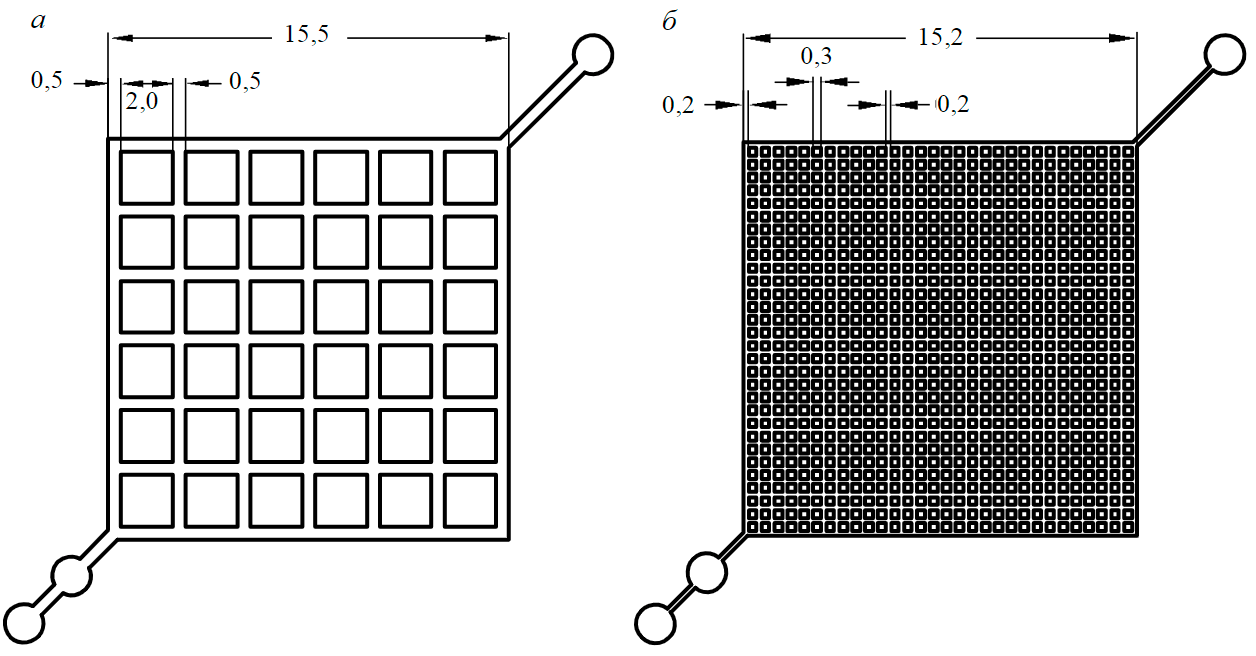
Fig.1. Topologies of microfluidic chips with a columns array imitating grains of porous medium:
a – N 1; b – N 2
Topology N 2 differs in the dimensions of the posts (0.3 mm side), the distance between the posts and chamber walls (0.2 mm each) and the dimensions of the chamber (15.2x15.2x0.2 mm). In topology chamber N 2, an array of 30´30 columns was formed (900 pcs. total). The aspect ratio of these structures in topology N 2 is 2:3.
For the manufacture of a secondary master mold, a double silicone image technique was proposed [31], but preliminary experiments have shown that it is not suitable for the formation of internal structures with a.r. more than 1:4. A significant distortion of the master mold bottom plane was observed, which made it impossible to seal the chip at the last stage of manufacturing (Fig.2). Therefore, the goal of this work is to adapt the previously proposed technique for manufacturing master molds in relation to the problems of manufacturing chips for working with oil, including for studying oil recovery, which require the formation of structures with a.r. in the chip. at least 2:3. It is necessary to find an intermediate molding material for making a negative impression from the positive channeled surface of PMMA, which can be used as a master mold for casting PDMS. The material should not strongly distort the geometry of the chip and, after curing, have low adhesion to PMMA and PDMS polymerized in it to separate the mold.
Methodology
The most accessible and technologically simplest material for milling microfluidic chips is PMMA, the basic rules for working with which is preventing the cut zone from overheat and using a sharp tool. The channeled surface of PMMA can be sealed by gluing a smooth plate of the same material to it, for example, using solvents [32-35]. This will allows to get a ready-made microfluidic chip.
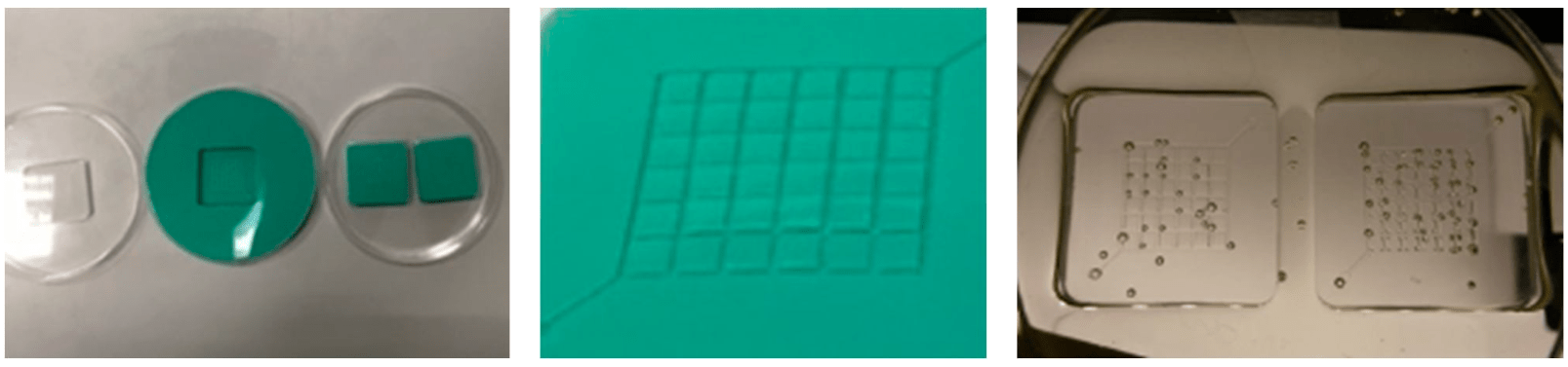
Fig.2. Epoxy master mold obtained by the method of double silicone image with Elite Double 22 mass (Zhermack SpA, Italy) [31]
The channeled surface was formed by milling in water on the surface of a PMMA plate (Novattro, Russia) with a nominal thickness of 2 mm. Milling topology N 1 was carried out with a two-tooth milling cutter with a diameter of 200 µm with a working part length of 0.6 mm (RM-0020.3.006.40, RDM, Russia) with a cutting speed of 9.42 m/min, feed per tooth – 2.5 µm, cutting depth – 30 µm. Milling topology N 2 was performed with a single-tooth cutter with a diameter of 0.5 mm and a length of the working part of 1.5 mm (0068005E, Datron, Germany), a cutting speed of 23.56 m/min was selected, feed per tooth was 5 µm, and the cut depth was 50 µm.
Negative image were taken from the prepared positive channeled PMMA surface (primary master mold), which were secondary master molds for pouring PDMS into them. The following two-component epoxy adhesive (Novocolor, Russia), Type R614 & R123 epoxy composition (Soloplast-Vosschemie, France) and MixArt Resin epoxy painting composition (EpoximaxX, Russia) were used for the secondary master mold manufacture. The pouring took place in Petri dishes made of polystyrene (CJSC Perint, Russia): a PMMA plate with a positive milled pattern was glued to the bottom of a Petri dish of suitable sizes using double-sided adhesive tape so that the channeled surface was on top. The mixed and degassed epoxy composition was poured into the cup to hide the chip under a layer of at least 5 mm, after which the repeated degassing was carried out. The sample was left overnight, after which its final polymerization was carried out at a temperature of 80 °C for one hour. The PMMA plate was removed at room temperature using levers; partial chipping of the upper edge of the epoxy master mold was observed. The resulting debris was removed by a jet of air.
The working degassed mixture of PDMS Sylgard-184 (Dow Corning, USA) was poured into the prepared master molds. Preparation of the working mixture and polymerization of PDMS were carried out in accordance with the manufacturer's instructions. PDMS chips were sealed with glass slides, which were washed with OSCh OP-1 isopropyl alcohol (Vekton JSC, Russia) and then with distilled water. A jet of air blew residual liquids away. The work was carried out without the use of a clean box, if dust particles accidentally got in, they were removed using clerical adhesive tape FT510281676 Scotch “Magic” (3M, USA). Next, plasma cleaning and activation of the joint surfaces (the channeled surface of the PDMS chip and the surface of the glass slide) were carried out. For this purpose, the apparatus d'Arsonval DE-212 KARAT (LLC “SMP”, Russia) was used with an all-metal electrode, which moved over the treated surfaces at a distance of 1-2 mm for two minutes [36]. After treatment, the surfaces were pressed against each other so that their adhesive coalescence occurred. Then the resulting microfluidic chip was heated at a temperature of 125 °C for 15 min to catalyze the covalent siloxane bond between glass and PDMS.
The choice of material for the master mold for casting chips from PDMS
Master molds were made from three epoxy compositions, manufacturing features for each of the options were identified, and the most technologically advanced and providing minimal shape distortion was selected.
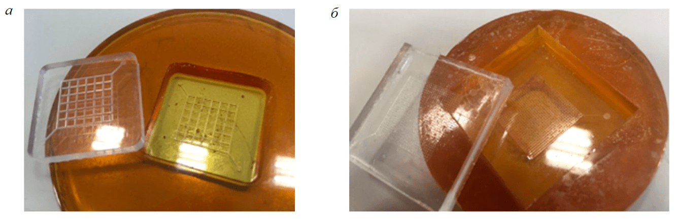
Fig.3. Primary PMMA master mold and secondary master mold made of universal epoxy two-component adhesive (a); secondary master mold from the same epoxy composition and a PDMS chip with impaired polymerization at the point of contact with the master mold (b)
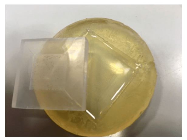
Fig.4. PMMA chip and epoxy resin master mold taken from it Type R614 & R123
Universal epoxy two-component adhesive from Novokolor is quite viscous and has a short setting time (according to the instructions 1 h, but actually ~20 min), which makes it difficult to complete vacuum degassing before pouring. After hardening, this composition retains elasticity. The primary master shape with topology N 1 (a.r. 1:4) was extracted from this composition without much difficulty, and the geometry was not damaged. When extracting topology N 2 (a.r. 2:3), the strength of the material was not enough – most of the columns came off and remained in the primary master form.
In some of the resulting master molds from this material, PDMS polymerization was inhibited near the surface boundary, which led to an unpredictable result. Therefore, despite the fact that several successful high-quality master molds have been obtained from this material, its use is not recommended (Fig.3).
Epoxy compound Type R614 & R123 can be used after mixing for one hour, which, combined with its high fluidity, is sufficient to fill visible topology structures and remove bubbles. This makes the material very convenient for high-quality pouring. After polymerization, it has low elasticity. Difficulties arose in the process of extracting the primary master mold from PMMA: structures with a.r. more than 2:3 are damaged. Figure 4 shows that 55 out of 900 columns were torn out during the extraction of the primary mother-form from the secondary. At the same time, the resulting secondary master form does not interfere with the polymerization of PDMS and has very low adhesion to it, which does not contradict the known results [22]. Due to its high strength, this material is suitable for making high-quality master molds on already made elastic PDMS chips, but not on rigid PMMA primary molds. Epoxy compound Type R614 & R123 is recommended for scaling up the production of a previously made high aspect ratio PDMS sample. Thus, it allows to accurately and repeatedly copy a master mold made by another method, such as lithography.
Epoxy painting compound MixArt Resin (EpoximaxX, Russia) is less fluid compared to Type R614 & R123. Its time of usage after kneading (55 min) is not enough for complete degassing and removal of bubbles. On the other hand, this time is enough for the bubbles to rise and move away from the canalized surface, which is located at the bottom of the container where the filling is carried out. After hardening, the master form from this composition becomes quite strong and inelastic. But its adhesion to polystyrene, PMMA and PDMS is very low and there were practically no problems with the extraction of the primary master form – one column out of 900 was torn out (Fig.5). The use of this epoxy resin is recommended for making negative epoxy impressions of milled structures with a.r. 2:3 from PMMA surface.
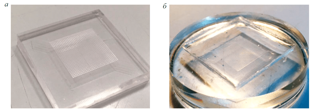
Fig.5. Primary master mold made of PMMA (a) and secondary master mold made of MixArt Resin epoxy resin removed from it (b)
Thus, a new technique was obtained for the manufacture of negative epoxy master molds for casting chips from PDMS with structures (a.r. ≥ 2:3). The table contains the main results of the study.
The features of the considered epoxy compositions for making a secondary master mold
|
Material name |
Number of damaged columns on topology N 2 with a.r. 2:3 (out of 900 pcs.), pcs. |
Identified benefits |
Identified difficulties |
|
Type R614 & R123 |
55 |
Good degassing, due to high fluidity it fills the form well |
Difficult removal of PMMA from the cast master mold |
|
Universal epoxy two-component |
> 300 |
High commercial availability of the material in Russia |
Variation in properties between |
|
MixArt Resin |
1 |
Relatively easy demoulding of PMMA |
Viscous: when filling the form, |
The use of microfluidic chip in the problems of oil recovery by flooding
An OB1 MK3+ (Elveflow, France) liquid supply system was connected to the chip using 20G blunt needles (AD720050, Adhesive Dispensing Ltd, Great Britain) and Tygon VE-ACUPEEK-076 elastic tubes (Saint-Gobain, France) with an inner diameter of 1/32". This system creates an overpressure that sets the fluid in motion, and in combination with a velocity sensor, it allows to get a flow with a fixed flow rate with a variable hydrodynamic resistance.
By the beginning of the observations, the chips were completely filled with water (demonstration N 1, Fig.6) or oil with a dynamic viscosity of 24.5 mPa s and a density of 0.83 g/cm3 (demonstration N 2, Fig.7), after which the liquid was displaced by water. Using a DSC-RX100M4 video camera (Sony, Japan), the dynamics of liquid displacement by water was filmed.
In demonstration N 1, the water with which the chip was prefilled was stained with Coomassie Brilliant Blue R-250 violet dye (Medigen ltd., Russia), and the water in which the displacement took place was stained with methyl orange (JSC Khimreaktivsnab, Russia) for flow contrast. Figure 6 shows the movement of the water front during its flow in a porous medium.
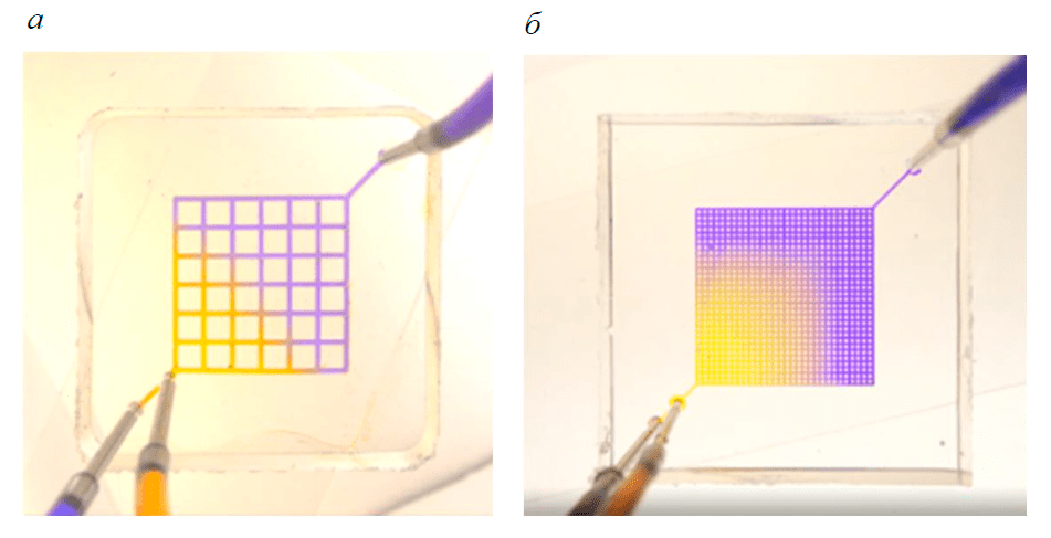
Fig.6. Microfluidic PDMS chips sealed with glass slides. Visualization of water flow using dyes: topology N 1 with a column side of 2 mm (a) and N 2 with a column side of 0.3 mm (b)
To demonstrate the displacement of oil, the manufactured microfluidic chip with topology N 2 was filled with oil, which was then displaced by water at a constant volume flow rate of 500 µl/min (Fig.7). The surface of PDMS in this case is oil-wettable, the value of the contact angle for oil is 46°. With this displacement mode, large areas of capillary-retained oil remain in the corners of the chip, and in the area washed with water, the proportion of residual oil is significant. Oil remains in the form of liquid bridges between the columns, simulating the grains of the porous medium. Each of these effects requires separate systematic studies on original microfluidic models, for the manufacture of which the obtained technology can be used, which is shown in Fig.7.
Conclusion
Pilot versions of experimental microscale models have been developed to study filtration processes during oil displacement.
As a result of numerous methodological experiments, a new technique for manufacturing negative epoxy master molds for casting PDMS microfluidic chips based on imprinting from the PMMA surface has been developed.
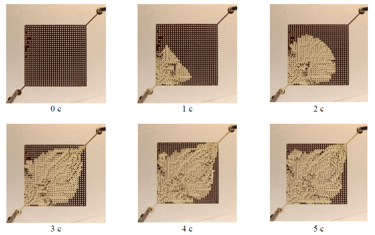
Fig.7. Displacement of oil with water at a flow rate of 500 µl/min at different time points (water was supplied diagonally from the lower left corner)
According to this technique, the pattern of the capillary network is made by milling on the PMMA surface, after which an impression is taken from the MixArt Resin epoxy composition, which is the master form. Mixed and degassed PDMS is poured into the resulting master mold and polymerized. Chips from PDMS are sealed with glass slides using the d'Arsonval apparatus.
The conducted debugging experiments showed that the developed technology for manufacturing microfluidic chips allows to carry out experiments with pumping oil for a long time. It was found that PDMS chips are not destroyed by prolonged contact with liquid hydrocarbons (48 h). The chips produced by this method are suitable for studying the flow of an oil emulsion in them for several days in a wide temperature range. Nevertheless, the manufactured chip does not claim to be a full-fledged model of the rock, but is a demonstration of the viability of the developed technique for its manufacture: it did not control the wettability of the surface [37, 38] and its modification (many techniques are known
[39, 40]); no attention was paid to the type of porosity, the shape of porous bodies and necks [2].
PDMS chips can be used to apply photoresist by microstamp (microcontact printing) in soft lithography [41] on the metallized glass surface, which opens the prospect for further research on the technology of transferring milled microfluidic topology to glass without the use of expensive diamond tools or clean rooms and maskless laser lithographs.
The described technique for manufacturing microfluidic chips from an optically transparent material allows a wide range of laboratories to develop microfluidic models for the quantitative analysis of the movement of various fluids in rocks, including water flows and the initial stages of rock erosion. Also, the technique actualizes the development of instruments and systems for optical quantitative determination of residual oil saturation in individual structures and other more complex rock models.
References
- Bazazi P., Sanati-Nezhad A., Hejazi S.H. Role of chemical additives on water-based heavy oil mobilization: A microfluidic approach. Fuel. 2019. Vol. 241, p. 1195-1202. DOI: 10.1016/j.fuel.2018.12.099
- Joseph J., Gunda S.K., Mitra S.K. On-chip porous media: Porosity and permeability measurements. Chemical Engineering Science. 2013. Vol. 99, p. 274-283. DOI: 10.1016/j.ces.2013.05.065
- Vavra E.D., Yongchao Zeng, Siyang Xiao et al. Microfluidic devices for characterizing pore-scale event processes in porous media for oil recovery applications. Journal of Visualized Experiments. 2018. Vol. 131. N e56592. DOI: 10.3791/56592
- Saadat M., Yang J., Dudek M. et al. Microfluidic investigation of enhanced oil recovery: The effect of aqueous floods and network wettability. Journal of Petroleum Science and Engineering. 2021. Vol. 203. N 108647. DOI: 10.1016/j.petrol.2021.108647
- Fuwei Yu, Hanqiao Jiang, Fei Xu et al. New insights into flow physics in the EOR process based on 2.5D reservoir, micromodels. Journal of Petroleum Science and Engineering. 2019. Vol. 181. N 106214. DOI: 10.1016/j.petrol.2019.106214
- Gladkikh E.A., Khizhnyak G.P., Galkin V.I. Influence of Filtration Capacitive Properties of Development Objects on the Value of Oil Displacement Efficiency in Various Geological and Physical Conditions. Bulletin of the Tomsk Polytechnic University. Geo Аssets Engineering. 2018. Vol. 329. N 7, p. 77-85 (in Russian).
- Gladkikh E.A., Galkin V.I., Khizhniak G.P. The Method for Estimating the Oil Displacement Coefficient Based on Standard Core Analysis. Oil Industry. 2017. N 8, p. 90-93 (in Russian). DOI: 10.24887/0028-2448-2017-8-90-93
- Das A., Mohanty K., Nguyen Q. A pore-scale study of foam-microemulsion interaction during low tension gas flooding using microfluidics – Tertiary recovery. Journal of Petroleum Science and Engineering. 2021. Vol. 203. N 108596. DOI: 10.1016/j.petrol.2021.108596
- Elyaderani S.M.G., Jafari A. Microfluidics experimental study in porous media applied for nanosilica/alkalineflooding. Journal of Petroleum Science and Engineering. 2019. Vol. 173, p. 1289-1303. DOI: 10.1016/j.petrol.2018.08.039
- Huiyu Wang, Bei Wei, Zezheng Sunet et al. Microfluidic study of heavy oil emulsification on solid surface. Chemical Engineering Science. 2021. Vol. 246. N 117009. DOI: 10.1016/j.ces.2021.117009
- Lin Y.J., He P., Tavakkoli M. et al. Examining asphaltene solubility on deposition in model porous media. Langmuir. 2016. Vol. 32. Iss. 34, p. 8729-8734. DOI: 10.1021/acs.langmuir.6b02376
- Martyushev D.A., Vinogradov J. Development and application of a double action acidic emulsion for improved oil well performance: laboratory tests and field trials. Colloids and Surfaces A: Physicochemical and Engineering Aspects. 2021. Vol. 612. N 125998. DOI: 10.1016/j.colsurfa.2020.125998
- Martyushev D.A., Govindarajan S.K. Development and study of a visco-elastic gel with controlled destruction times for killing oil wells. Journal of King Sand University – Engineering Sciences. 2021. DOI: 10.1016/j.jksues.2021.06.007
- Derendyaev R.A., Zakharov L.A., Martyushev D.A., Derendyaev K.A. Improving the Efficiency of Application of Technology on Water Performance Limitation Based on Geological and Physical Characteristics of the Plates (on the Example of Deposits of the Perm Region). Bulletin of the Tomsk Polytechnic University. Geo Аssets Engineering. 2019. Vol. 330. Iss. 9, p. 154-163 (in Russian). DOI: 10.18799/24131830/2019/9/2264
- Song W., de Haas T.W., Fadaei H., Sinton D. Chip-off-the-old-rock: the study of reservoir-relevant geological processes with real-rock micromodels. Lab on a Chip. 2014. Vol. 14. Iss. 22, p. 4382-4390. DOI: 10.1039/C4LC00608A
- Safari A., Rashidi F., Kazemzadeh E., Hassani A. Determining optimum acid injection rate for a carbonate gas reservoir and scaling the result up to the field conditions: A case study. Journal of Natural Gas Science and Engineering. 2014. Vol. 20, p. 2-7. DOI: 10.1016/j.jngse.2014.05.017
- Xiaqing Li, Guicai Zhang, Jijiang Ge. Potential formation damage and mitigation methods using seawater-mixed acid to stimulate sandstone reservoir. Journal of Natural Gas Science and Engineering. 2016. Vol. 35, p. 11-20. DOI: 10.1016/j.jngse.2016.08.034
- Xuezhi Zhao, Yujun Feng, Guangzhi Liao, Weidong Li. Visualizing in-situ emulsification in porous media during surfactant flooding: A microfluidic study. Journal of Colloid and Interface Science. 2020. Vol. 578, p. 629-640. DOI: 10.1016/j.jcis.2020.06.019
- Xiaolong Peng, Xiangzeng Wang, Xiang Zhou et al. Lab-on-a-chip systems in imbibition processes: A review and applications/issues for studying tight formations. Fuel. 2021. Vol. 306. N 121603. DOI: 10.1016/j.fuel.2021.121603
- Temiz Y., Lovchik R.D., Kaigala G.V., Delamarche E. Lab-on-a-chip devices: How to close and plug the lab? Microelectronic Engineering. 2015. Vol. 132, p. 156-175. DOI: 10.1016/j.mee.2014.10.013
- Ríos Á., Zougagh M., Avila M. Miniaturization through lab-on-a-chip: Utopia or reality for routine laboratories? A review. Analytica Chimica Acta. 2012. Vol. 740, p. 1-11. DOI: 10.1016/j.aca.2012.06.024
- Posmitnaya Y.S., Bukatin А.S., D.А. Makarov et al. Alternative Solutions of Master Molds Creation for Fabrication Microfluidic Chips by “Soft” Lithography. Nauchnoe priborostroenie. 2017. Vol. 27. N 2, p. 13-20 (in Russian). DOI: 10.18358/np-27-2-i1320
- Gale B.K., Jafek A.R., Lambert C.J. et al. A review of current methods in microfluidic device fabrication and future commercialization prospects. Inventions. 2018. Vol. 3. Iss. 3. N 60. DOI: 10.3390/inventions3030060
- Alrifaiy A., Lindahl O.A., Ramser K. Polymer-based microfluidic devices for pharmacy, biology and tissue engineering. Polymers. 2012. Vol. 4. Iss. 4, p.1349-1398. DOI: 10.3390/polym4031349
- Behroodi E., Latifi H., Bagheri Z. et al. A combined 3D printing/CNC micro-milling method to fabricate a large-scale microfluidic device with the small size 3D architectures: an application for tumor spheroid production. Scientific Reports. 2020. Vol. 10. Iss. 1, p. 1-14. DOI: 10.1038/s41598-020-79015-5
- Guckenberger D.J., de Groot T.E., Wan A.M.D. et al. Micromilling: a method for ultra-rapid prototyping of plastic microfluidic devices. Lab on a Chip. 2015. Vol. 15. Iss. 11, p. 2364-2378. DOI: 10.1039/C5LC00234F
- Evstrapov A.A., Lukashenko T.A., Gorny S.G., Yudin K.V. Microfluidic Chips in Poly (Methyl Methacrylate): Method of Laser Ablation and Thermal Binding. Nauchnoe priborostroenie. 2005. N 2, p. 72-81 (in Russian).
- Germash N.N., Esikova N.A., Afonicheva P.K., Evstrapov A.A. Research of replication accuracy in some elastomer materials with different Young’s modulus. International Conference PhysicA.SPb/2021, 18-22 October 2021, Saint Petersburg, Russia. Journal of Physics: Conference Series. 2021. Vol. 2103. N 012054. DOI: 10.1088/1742-6596/2103/1/012054
- Bukatin A.S., Mukhin I.S., Malyshev E.I. et al. Fabrication of High-Aspect-Ratio Microstructures In Polymer Microfluid Chips For In Vitro Single-Cell Analysis. Technical Physics. 2016. Vol. 61. N 10, p. 1566-1571.
- Isiksacan Z., Guler M.T., Aydogdu B. et al. Rapid fabrication of microfluidic PDMS devices from reusable PDMS molds using laser ablation. Journal of Micromechanics and Microengineering. 2016. Vol. 26. N 3. N 035008. DOI: 10.1088/0960-1317/26/3/035008
- Yakimov A.S., Osipova E.D., Morgun A.V. et al. Measuring Microfluidic System for the Mammalian Brain Cells Cultivation. Nauchnoe priborostroenie. 2019. Vol. 29. Iss. 4, p. 51-56 (in Russian). DOI: 10.18358/np-29-4-i5156
- Lukashenko T.A., Tupik A.N., Rudnitskaya G.E. et al. Thermal, Adhesive and Solvent Bonding Techniques for Polymer and Polymer-Glass Microchip Device Fabrication. Nauchnoe priborostroenie. 2016. Vol. 26. N 2, p. 64-74 (in Russian).
- Bamshad A., Nikfarjam A., Khaleghi H. A new simple and fast thermally-solvent assisted method to bond PMMA–PMMA in micro-fluidics devices. Journal of Micromechanics and Microengineering. 2016. Vol. 26. N 6. N 065017. DOI: 10.1088/0960-1317/26/6/065017
- Faghih M.M., Sharp M.K. Solvent-based bonding of PMMA–PMMA for microfluidic applications. Microsystem Technologies. 2019. Vol. 25. Iss. 9, p. 3547-3558. DOI: 10.1007/s00542-018-4266-7
- Chia-Wen Tsao, DeVoe D.L. Bonding of thermoplastic polymer microfluidics. Microfluidics and nanofluidics. 2009. Vol. 6. Iss. 1, p. 1-16. DOI: 10.1007/s10404-008-0361-x
- Haubert K., Drier T., Beebe D. PDMS bonding by means of a portable, low-cost corona system. Lab on a Chip. 2006. Vol. 6. Iss. 12, p. 1548-1549. DOI: 10.1039/B610567J
- Alroudhan A., Vinogradov J., Jackson M.D. Zeta potential of intact natural limestone: Impact of potential-determining ions Ca, Mg and SO4. Colloids and Surfaces A: Physicochemical and Engineering Aspects. 2016. Vol. 493, p. 83-98. DOI: 10.1016/j.colsurfa.2015.11.068
- Khayrullin M.M., Zakirov T.R., Grishin P.A. et al. Methods for Studying Two-Phase Flows in Porous Media: Numerical Simulation and Experiments on Microfluidics Chips. SPE Russian Petroleum Technology Conference. 2020. DOI: 10.2118/202022-MS
- Ignatchik M.M., Posmitnaya Y.S., Evstrapov A.A. Study of Modification Wetting Properties of the Surface of Polydimethylsiloxane and the Microchannel after Exposure by High-Frequency Plasma in Oxygen. Nauchnoe priborostroenie. 2016. Vol. 26. N 1, p. 41-46. DOI: 10.18358/np-26-1-i4146
- Zhou J., Ellis A.V., Voelcker N.H. Recent developments in PDMS surface modification for microfluidic devices. Electrophoresis. 2010. Vol. 31. Iss. 1, p. 2-16. DOI: 10.1002/elps.200900475
- Dong Qin, Younan Xia, Whitesides G.M. Soft lithography for micro-and nanoscale patterning. Nature protocols. 2010. Vol. 5. N 3, p. 491-502. DOI: 10.1038/nprot.2009.234