
Improving the efficiency of relay protection at a mining and processing plant
- 1 — Ph.D., Dr.Sci. Moscow Polytechnic University ▪ Orcid
- 2 — Ph.D. North Caucasian Mining and Metallurgical Institute (State Technological University) ▪ Orcid ▪ Elibrary ▪ Scopus
- 3 — Ph.D. North Caucasian Mining and Metallurgical Institute (State Technological University) ▪ Orcid ▪ Elibrary ▪ Scopus

Abstract
The paper presents the results of constructing effective relay protection in the power supply system of a mining and processing plant (MPP). A brief description of the MPP is given, the power supply and substitution circuits used to calculate the short-circuit currents are given. A statistical analysis of failures in the electric network of the MPP has been carried out, which makes it possible to draw conclusions about the nature of failures ranges. Analysis of the registered faults shows that a significant part of them are line-to-earth faults, which in most cases turn into multiphase short circuits, which are interrupted by overcurrent protection. In order to improve the efficiency and reliability of the relay protection, the power supply scheme of the MPP was refined and analyzed. The calculation of the short-circuit currents was made, which made it possible to calculate the settings of the relay protection and give recommendations on the place of its installation and adjustment in order to ensure the normal operation of electricity consumers. To reduce the number of failures to the cable insert on the line leaving the administrative and household complex (AHC), and to increase the reliability of power supply to consumers, it is advisable to divide the capacities of the existing 10 kV line into two parallel ones by laying a second line. It is recommended to install a current cut-off on the line outgoing to the AHC, the feasibility of the installation of which was shown by calculations. This will reduce the chance of failures to the cable gland. Data on the setting currents of overcurrent protection and current cut-off are given on the selectivity card.
None
Introduction
Increasing the efficiency of enterprises is possible only with the correct use of scientific and technical solutions for the operation and optimal operating modes of the power supply system (PSS). The correct choice of relay protection devices and their adjustment, leading to an increase in the selectivity and reliability of its operation, is important for the optimal operating mode of the PSS. When the load of consumers changes, the PSS operation mode becomes different, therefore, it is necessary to assess the effect of the load on losses in the PSS.
Formulation of problem
One of the most important tasks for PSS of mining and processing plants is to ensure the effective functioning of relay protection and automation systems. This is necessary to reduce the negative effect of possible failures and abnormal modes caused by short circuits. To solve this problem, for one of the largest mining and processing enterprises of the Russian Federation, an effective relay protection was built on the basis of comprehensive research. The implementation of the recommendations proposed in the work will improve the reliability and efficiency of relay protection in the PSS of the MPP and get the corresponding economic effect.
Brief description of the MPP
Power supply to consumers with a 10 kV voltage of the MPP is carried out from the buses of the 10 kV substation “Promploshchadka” and from the central distribution substation: CDS-10 kV from two bus sections operating separately by feeders feeding the lines to the administrative and household plant (AHC) (Fig. 1); to the substation “Khrustalnaya”; to a transformer substation (TSS-9); from the 3rd cell of the outer switchgear complex (OSC-10 kV). For example, in Fig.1 the diagram of the MPP power supply with the supply lines to the AHC is shown, the rest of the diagrams are not presented in the work.
Outgoing lines are made by overhead and cable power lines (mixed), which can be seen from the power supply schemes. The cross-section of overhead lines fluctuates in insignificant limits: AS-95 – AS-50 (A-50). Cross-sections of cable lines – from 50 to 240 mm 2 brands AAShV and ASB. The lengths of the sections of cable and overhead lines vary over a very wide range, depending on the distance of electrical receivers, substations and on the availability of materials at the time of their construction. The number of power consumers, i.e. the number of transformer substations on each line is very significant (up to 19-20). Capacities range are from 100 to 630 kVA.
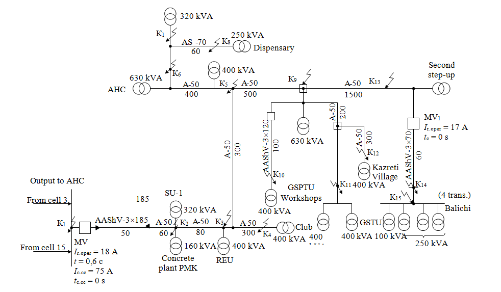
Fig.1. Power supply diagram of the MPP with power lines to the AHC
Statistical analysis of failures in the electric grid of the MPP
Statistical material allows us to draw some conclusions about the nature of the failures distribution for the specified period [8, 21]. A total of 120 failures were registered, of which 58, i.e. about 50 %, falls on the feeder, outgoing from cells 3 and 15 of the substation “Promploshchadka”, which is significant for a small site with a large number of connected substations. The registration of damages is given in the log of the main step-down substation (MSDS) based on the operation of the overcurrent protection (OCP), current cut-off (CC) from short-circuit currents, as well as during the operation of the ground protection alarm.
Analysis shows that a significant part of the faults are single-phase earth faults, which in most cases turn into multi-phase short circuits, which are disconnected by overcurrent protection [9, 18]. The analysis graphs of the number of failures for the specified period (Fig.2) illustrate the majority of failures along the feeder at the AHC, which fall on January, April, May and December 2017, 2018 and partially 2019. The feeder of cell 3 to the tailings facility (Fig.3) illustrates the amount of failure, most of which occurs in February, April, May 2017, June 2018 and August 2019.
A large number of registered failures are determined by insufficient preventive measures and a small amount of precipitation over the specified period.
The causes of failures to electrical installations depend on many factors and are varied in nature. However, from the electrical equipment downtime log, in almost all cases, the cause of failure and disconnection of elements is unclear, it only indicates which protection disables the failure. Failures can be divided into the following types: cable breakdown, failure to the insulators of the overhead line, breakage of the overhead power line, mechanical damage, damage to the supply line (short circuit on the line, overwhelming wires). It is advisable, after finding out the type of failure, to make an entry in the downtime log of electrical equipment about its cause [2, 4, 14].
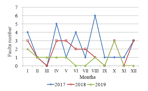
Fig.2. The number of damages along the feeder at the AHC for certain months of 2017-2019
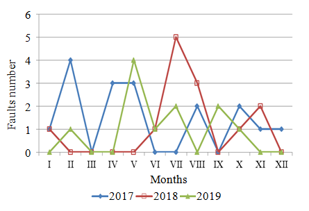
Fig.3. The number of damages along the feeder of cell 3 on tailings facility for certain months of 2017-2019
Thus, the main novelty of the work is the identification of failure caused by short-circuit currents.
Analysis of failures in the power grid of the MPP
To reduce the absolute number of faults in the 10 kV electrical network, the overall level of its operation should be increased. Special care is required to carry out preventive measures before spring and in winter, when the maximum damage occurs. It is necessary to pay attention to carrying out preventive maintenance in the middle and at the end of the week, since the bulk of the damage occurs during this period. Since it is impossible to assess the damage from the electrical equipment downtime log, it is advisable for the substation duty personnel to find out the reason for the protection operation and note it in the failure log. This is necessary for targeted preventive work to reduce certain types of failure.
Calculation of relay protection in electric networks of MPP
In recent years, the power consumption in industry has been increasing, which entails an increase in the capacity of transformers and the length of power transmission lines. An example is the Madneupol Mining and Processing Plant (MMPP) [7, 17].
The main step-down substation of MMPP supplies power to the main and auxiliary subdivisions. The main divisions include an open pit mine and a concentrator [3]. Auxiliary, but very responsible electricity consumers are an urban-type settlement, a workshop for special garages, a concrete center, a club, a dispensary, as well as neighboring villages, which are powered by power lines from the MMPP MSDS.
The most important indicators of the normal operation of these electrical receivers are uninterrupted power supply and reliability. This does not always correspond to the specified requirement, since the electrical network has significant ramification, and relay protection and automation do not work clearly and reliably enough [20, 23]. The consequence is non-selective disconnection of many electrical consumers, undersupply of electricity and, thus, downtime of electrical equipment. This, in turn, worsens the technical and economic indicators of the work of many units and harms the population and personnel servicing the main and auxiliary production. It is necessary to rationalize, improve the efficiency and reliability of relay protection and automation in the electrical networks of MMPP [16, 19, 22].
Using the refined power supply scheme, the short circuit currents were calculated, which made it possible, having the numerical values of the short circuit currents, to calculate the relay protection settings and give recommendations on the place of its installation and adjustment in order to ensure the normal operation of electricity consumers [12, 13].
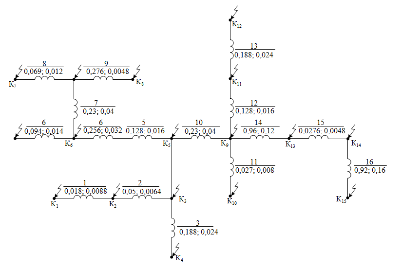
Fig.4. Equivalent circuit indicating the active and inductive resistance of the line outgoing from cell 3, 15 on the AHC
The paper presents a method for calculating short-circuit currents in the PSS of the MPP and on its basis an analysis of the relay protection of outgoing cable lines is carried out. Similar results for calculating the parameters of relay protection were obtained for other consumers of electricity at the mine, but due to the limited scope of work, they were not presented.
Method for calculating short-circuit currents in the power supply system of MMPP with voltage above 1000 V
To calculate the short-circuit currents, computational schemes and corresponding equivalent circuits for the lines emanating from the OSC-10 kV cells of the MSDS, the 10 kV “Promploshchaka” substation and the CPDS are drawn up. The equivalent circuit for the circuit shown in Fig.1 is shown in Fig.4.
The calculation uses the method of approximate reduction, in which the voltage at all stages of transformation is taken to be equal to the average Uav.
To calculate the short-circuit current downstream of the transformer, you need to know the short-circuit power. To determine the short-circuit power behind the MSDS power transformer, we use the formula
where St.nom – nominal power of the transformer, kVA; usc – short-circuit voltage as a percentage of nominal voltage Unom.
A three-winding power transformer of TDTN-25/110 type with usc = 10.5 kV is installed at the MSDSfor winding with voltage of 10.5 kV,
Short-circuit current on the 10.5 kV side of the transformer at the point К1:
where Uav2 – assumed value of the average voltage downstream of the transformer on the 10 kV side,
According to the specified and refined power supply scheme of the MMPP, a calculated equivalent circuit is drawn up, taking into account the fact that when calculating short-circuit currents, it is necessary to take into account the active resistance, provided that the ratio r/x > 1/3.
The system resistance is determined based on the calculated value of the short-circuit current downstream of the transformer on the 10.5 kV side: zs = хs = 0.508 Ohm.
Active and inductive resistances (r and x) of cable and overhead lines are determined from the following considerations:
- the inductive resistance of the cable is calculated on the basis that x0 = 0.08 Ohm/km is the specific resistance of 1 km of the line, depending on the type of line, the material of the wires, the method of performing power lines with a voltage of 10.5 kV;
- the active resistance of the line is determined by the well-known expression, which includes the conductivity of the cable lines and the cross-section of the line under consideration;
- inductive resistance of overhead lines is calculated for cable lines, data on specific resistance per 1 km of line are taken from reference data.
The calculation of three- and two-phase short-circuit currents is carried out according to the formulas:
where zres – the resulting value of the resistance of the short circuit (from the power supply to the short circuit point), $z_{res}=\sqrt{(x_{res})^2+(r_{res})^2}$; sum of inductive resistances of line sections to the point of short circuit $x_{res}=\sum_1^nx=x_1+x_2+ \cdot \cdot \cdot+x_n$; the sum of the active resistances of the line sections to the point of short circuit $r_{res}=\sum_1^nr=r_1+r_2+ \cdot \cdot \cdot+r_n$.
Since, according to the condition, r/x > 1/3, the active resistance rres must be taken into account when calculating the short-circuit currents.
According to the formulas given, the values of the currents of three- and two-phase short circuits are calculated. The equivalent circuit, which indicates the values of the resistances of the network elements, the calculation of which must be made, is shown in Fig.4. The results of calculating the currents of three- and two-phase short circuits are summarized in Table 1.
Table 1
Data for calculating short-circuit currents and the magnitude of the currents of three- and two-phase
short circuits of the line outgoing from cells 3 and 15 at the AHC
|
Short-circuit point |
rres, Ohm |
хres, Ohm |
zres, Ohm |
Isc(3), А |
Isc(2), А |
|
К1 |
– |
0.508 |
0.508 |
12501 |
10826 |
|
К2 |
0.018 |
0.5168 |
0.5171 |
12281 |
10635 |
|
К3 |
0.068 |
0.5232 |
0.5276 |
12037 |
10424 |
|
К4 |
0.256 |
0.5472 |
0.6041 |
10512 |
9103 |
|
К5 |
0.35 |
0.5612 |
0.6614 |
9602 |
8315 |
|
К6 |
0.734 |
0.6092 |
0.9538 |
6658 |
5765 |
|
К7 |
1.033 |
0.6612 |
1.2264 |
5178 |
4484 |
|
К8 |
0.9916 |
0.654 |
1.1878 |
5346 |
4630 |
|
К9 |
0.67 |
0.6012 |
0.9001 |
7055 |
6110 |
|
К10 |
0.697 |
0.6092 |
0.9257 |
6860 |
5941 |
|
К11 |
0.798 |
0.6172 |
1.0088 |
6295 |
5452 |
|
К12 |
0.986 |
0.6412 |
1.1761 |
5399 |
4676 |
|
К13 |
1.63 |
0.7212 |
1.7824 |
3563 |
3085 |
|
К14 |
1.6576 |
0.726 |
1.8096 |
3509 |
3039 |
|
К15 |
2.5776 |
0.886 |
2.7256 |
2330 |
|
A selectivity map for the operation of overcurrent protections in the 10 kV electrical network of MMPP is being drawn up. In accordance with the PUE, on single lines with one-way power supply from multiphase faults, a two-stage current protection should be installed, the first stage of which is made in the form of a current cutoff, and the second – overcurrent protection with an independent or dependent time delay characteristic.
Since the mixed cable-air network with a voltage of 10 kV MMPP is an open radial network with one-way power supply, it is provided for the installation and calculation of OCP (overcurrent protection) and MS. The selectivity map of relay protection is drawn up in the following sequence:
- the equivalent circuit of the electric network for each of the lines discussed above is drawn up;
- resistances of individual elements of the circuit are determined in accordance with the brand, section and length of the lines;
- currents of three- and two-phase short circuits are calculated at separate points of the network;
- protection operation currents are determined at the points of connection of step-down substations and on each outgoing line at the places of protection installation;
- the sensitivity coefficient ksens is determined;
- time delays of OCP are set.
Using the data on the calculation of three- and two-phase short-circuit currents for individual outgoing radial lines, the operating current is calculated and the selected protection is checked for sensitivity. The operating current of the overcurrent protection is determined by the formula
where ksafety = 1.1-1.2 – safety factor; kss – self-start ratio; Ioper.max – maximum operating current (rated current of consumers), А; kr – return rate, kr = 0.6-0.7 – for RTM type relays, kr = 0.8-0.85 – for relay type RS40.
Relay operating current
where ksch – circuit coefficient equal to 1 when two relays are turned on for phase currents according to incomplete Y scheme and equal to $\sqrt{3}$ when one relay is turned on for the difference in currents of two phases; nct – current transformer ratio.
Sensitivity factor
where I (2)scc = Iscc.min – two-phase short-circuit current at the end of the protected zone.
In accordance with the PUE(electrical installation rules) ksens ≥ 1.5 – in case of a short circuit at the end of the protected area, ksens ≥ 1.2 – with a short circuit at the end of an adjacent section, with the operation of overcurrent protection as a backup protection and for current cutoffs performed as backup.
The calculation of the current cut-off operation will be made according to the formula
where kbeg = 1.2-1.4; $I_{s.c.out.max.}^{(3)}$ – three-phase short-circuit current at the beginning of the adjacent section.
Let us calculate the relay protection of outgoing lines. Line – exit to the AHC from cells 3 and 15 (see Fig.1).
- An OCP is installed on the line under consideration at MV1 (next to the “2nd step-up” substation).
We consider the maximum load Ioper.max according to the rated power of the connected transformers to the outgoing line for MV1 (see Fig.1). Determine the operating current for MV1 by the expression (5):
where
Relay operating current by expression (6):
For the installation, we select an electromagnetic microprocessor relay of the PC40/20 type with an operating current of 17 A.
Checking the protection sensitivity by expression (7):
We get ksens > 1.5, i.e. protection is quite sensitive to short-circuit current at the beginning of the coverage area (at point K15).
The operation of networks with a voltage of 10 kV of outgoing lines from DSS-10 showed that in the section of the outgoing line at the AHC, when short-circuit currents of 10-12 kA flow, the cable insert at the beginning of the specified line fails very often. This leads to the blackout of a large number of consumers, including the village of Kazreti, which is powered by this line [1, 5, 11]. The reason is the large value of the flowing short-circuit current and the long time of the relay protection acting on the current interruption [6, 10, 15]. To reduce the damage to the cable insert and increase the reliability of power supply to consumers, it would be advisable to divide the specified line into two parallel ones. To do this, you will need to operate separately cells 3 and 15 of the 10 kV substation “Promploschadka”, install 11 supports and lay 450 m of wires with a cross-section of A-50.
The short-circuit current limitation can be achieved by installing a reactor of the RB-10-630-0.25 type. This will increase the reliability of the oil circuit breakers during shutdown, the calculated values of the resistance of the short-circuit scheme and currents after the installation of the
RB-10-630-0.25 type reactor are given in Table 2.
Table 2
Active and inductive resistances for calculating short-circuit currents and currents three- and two-phase short circuits of the line outgoing from cells 3 and 15 at the AHC taking into account the resistance of the linear reactor
|
Short-circuit point. |
rres, Ohm |
хres, Ohm |
zres, Ohm |
Isc(3), А |
Isc(2), А |
|
К1 |
– |
0.758 |
0.758 |
8378 |
7255 |
|
К2 |
0.0180 |
0.7704 |
0.7706 |
8241 |
7137 |
|
К3 |
0.068 |
0.7768 |
0.7797 |
8145 |
7053 |
|
К4 |
0.256 |
0.8008 |
0.844 |
7524 |
6516 |
|
К5 |
0.35 |
0.8148 |
0.8867 |
7162 |
6202 |
|
К6 |
0.734 |
0.8628 |
1.1327 |
5606 |
4856 |
|
К7 |
1.033 |
0.9148 |
1.3798 |
4602 |
3986 |
|
К8 |
0.9916 |
0.9076 |
1.3442 |
4724 |
4091 |
|
К9 |
0.67 |
0.8548 |
1.086 |
5847 |
5064 |
|
К10 |
0.697 |
0.8628 |
1.1091 |
5726 |
4959 |
|
К11 |
0.798 |
0.8708 |
1.1811 |
5377 |
4657 |
|
К12 |
0.986 |
0.8948 |
1.3314 |
4770 |
4130 |
|
К13 |
1.6576 |
0.9448 |
1.8992 |
3343 |
2896 |
|
К14 |
1.6576 |
0.94 |
1.9055 |
3333 |
2886 |
|
К15 |
2.5776 |
1.1 |
2.8025 |
2266 |
1963 |
From Table 2 it follows that the installation of the reactor will significantly reduce short-circuit currents and increase the reliability of the power supply system of MMPP. Therefore, it seems appropriate to submit an application for the preparation of this reactor. However, in the absence of the possibility of installing the reactor at the present time, it is proposed to increase the speed of the existing OCP, which has a time delay. For this purpose, it is recommended to install a current cut-off on the feeder outgoing to the AHC.
Let us determine the sensitivity coefficient for OCP on the MV1 oil circuit breaker after the possible installation of the reactor (taking into account the calculated short-circuit currents in Table 3) according to the expression (7):
It is obvious that after the installation of the reactor, the sensitivity of the protection remains very high and, therefore, will work quite well.
- We calculate OCP on the oil switch МВCDSS at the beginning of the outgoing line to the AHC (cell 3 or 15). Similarly to the previous calculation, we consider that the maximum operating current will correspond to the current In= Inom.max = 300 А.
Determine the operating current of the overcurrent protection by the expression (5):
The relay operating current will be equal to the formula (6):
The installation accepts a relay of the PC40/20 type for a current value of 20 A with Ir.oper = 18 А.
Let us determine the sensitivity coefficient before installing the reactor by the expression (7):
After installing the reactor
Thus, the overcurrent protection will be sensitive both before and after the installation of the reactor.
- Let's calculate the current cutoff actuation on the line outgoing to the AHC from cell 3 or 15 for МВCDSS. The calculation is carried out according to the formula (8).
Before installing the reactor:
It is accepted for installation of a relay of the PC40/100 type with Ir.oper = 80 A. The sensitivity coefficient is determined by the expression (7):
Current cutoff is sensitive because ksens > 2.
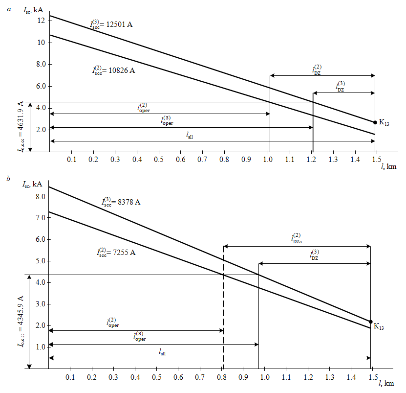
Fig.5. Graphical definition of the current cut off working area: a – $l^{(2)}_{oper}$ – working area with two-phase short closure (73.8 % lall); $l^{(3)}_{oper}$ – working area with three-phase short circuit (81.2 % lall); b – $l^{(2)}_{oper}$ – 54,4 %·lall; $l^{(3)}_{oper}$ – 65.8 %·lall; lDZ – current cut off dead zone
After installing the reactor:
Accepted for installation of a relay type PC40/100 with Is.c = 75 А. The sensitivity coefficient is determined by the expression (7):
The efficiency of the current cutoff after the installation of the reactor decreased to a value of ksens = 1.7. However, in accordance with the PUE for current cutoffs without time delay,
installed on the lines and performing the functions of additional protections, the sensitivity coefficient should be about 1.2 for a short circuit at the protection installation site in the most favorable mode according to the sensitivity condition.
The efficiency of the current cutoff for the line under consideration is determined graphically for two modes: before the installation of the reactor (Fig.5, a); after installing the reactor (Fig.5, b).
Figure 5 shows that the minimum value of the current cutoff working zone is 54 % of the length of the entire line, i.e. the cutoff is effective in both cases (with and without a reactor).
The response time of the protections on the line under consideration is indicated in Fig.1 and in Table 3 of the construction of the selectivity map, where the protection settings are indicated for the primary and secondary current Is.c и Ir.oper.
Table 3
Selectivity map of relay protection when power consumers are supplied from 10 kV radial lines
|
Outgoingline |
Protection installation place |
Protection type |
Current relaytype |
kсх |
Iо.c., А |
ntt |
Ir.oper, А |
ksens |
t, s |
Note |
|
From cells 3, 15 to AHC |
MV1 |
OCP |
CR-40/20 |
1 |
170 |
50/5 |
17 |
11.8 |
0 |
|
|
MVCDSS |
OCP |
CR-40/20 |
1 |
1080 |
300/5 |
18 |
2.8 |
0,6 |
|
|
|
CC |
CR-40/100 |
1 |
4800 |
300/5 |
80 |
2.26 |
0 |
Beforeinstallation reactor |
||
|
4500 |
75 |
1.7 |
Afterinstallingthereactor |
|||||||
|
From cell 14 output N 2 |
MV2 |
OCP |
CR-40/50 |
1 |
520 |
100/5 |
26 |
6.5 |
0 |
Ioper.max = 146.2 А |
|
MVCMM |
OCP |
CR-40/50 |
1 |
760 |
100/5 |
38 |
13.7 |
0,6 |
Ioper.max = 215.5 А |
|
|
From cell 4, output N 1 to ZHZB |
MV2 |
OCP |
CR-40/50 |
1 |
520 |
100/5 |
26 |
6.5 |
0 |
Ioper.max = 146.2 А |
|
MVZHZB |
OCP |
CR-40/20 |
1 |
900 |
300/5 |
15 |
5.6 |
0,6 |
|
|
|
CC |
CR-40/100 |
1 |
6000 |
300/5 |
100 |
1.78 |
0 |
|
||
|
From cell 15 input |
MV2 |
OCP |
CRM |
1 |
480 |
150/5 |
16 |
3.6 |
0 |
|
|
MV1 |
OCP |
CRV |
1 |
750 |
150/5 |
25 |
2.9 |
0,6 |
|
|
|
MVCDSS |
OCP |
CR-40/20 |
1 |
1020 |
300/5 |
17 |
7.8 |
1,1 |
|
|
|
Output from the 3rd cell of KRUN 10 kV |
MVKRUN |
OCP |
CR-40/50 |
1 |
720 |
150/5 |
24 |
3.5 |
0 |
Ioper.max = 218.8А |
For all other substations of the MPP, similar calculations were performed using the above method.
Conclusion
- To reduce the amount of damage to the cable insert on the line outgoing to the AHC, and to increase the reliability of power supply to consumers, it is advisable to divide the power of the existing 10 kV line into two parallel ones by laying a second line. To do this, you will need to use cells 3 and 15 separately, install 11 supports and lay 450 m of wires with a cross section of A-50.
- The limitation of the short-circuit current can be achieved by setting the RB-10-630-0.25 type. This will increase the reliability of the oil circuit breakers when disconnecting short-circuit currents (the calculated values of the circuit resistances and short-circuit currents before and after the installation of the RB-10-630-0.25 type reactor are given in Tables 1 and 2).
- It is recommended to install a current cut-off on the line outgoing to the AHC, the expediency of the installation of which has been shown by calculations. This will reduce the likelihood of damage to the cable insert. The data on the currents of the OCP and CC setting are given on the selectivity map (Table 3).
- It is recommended to set the minimum operating time of relay protection on outgoing lines.
- On the outgoing line from cell 14, output N 2 to the CMM at the installation site МВ2 to install current transformers 150/5 on In= 150 А instead of the existing 100/5, since Ioper.max = 146.2 А.
At the МВCMM installation site it is necessary to replace the existing current transformers with nтт = 100/5 to ТТ with nтт = 250/5, as Ioper.max = 215.5 А. - It is necessary to install a current transformer with nтт = 250/5, as Ioper.max = 218.8 A, on the outgoing line “output from the 3rd cell of KRUN-10 kV” instead of the existing current transformers with nтт = 150/5.
- The solution to the problem of constructing an effective relay protection at a MPP in this work consists in the development of a method for calculating short-circuit currents in PSS for the conditions of enterprises in mountainous areas with the calculation for a specific MPP. The developed methodology and the results obtained can be used at similar enterprises.
References
- Abramovich B.N. Uninterruptible power supply system for mining industry enterprises. Journal of Mining Institute. 2018. Vol. 229, p. 31-40. DOI: 10.25515/PMI.2018.1.31
- Klyuev R.V., Bosikov I.I., Gavrina O.A., Krysanov K.S. Analysis of the state of insulation of electrical equipment of mining and metallurgical companies. News of the Tula states university-sciences of earth. 2020. Vol. 2, p. 201-215 (In Russian).
- Golik V.I., Razorenov Yu.I., Karginov K.G. Mining industry – the basis for sustainable development of north Osse-tia-Alania. Sustainable development of mountain territories. 2017. Vol. 9. N 2(32), p. 163-172. DOI: 10.21177/1998-4502-2017-9-2-163-171 (in Russian).
- Klyuev R.V., Bosikov I.I., Mayer A.V., Gavrina O.A. Comprehensive analysis of the effective technologies applica-tion to increase sustainable development of the natural-technical system. Sustainable Development of Mountain Territories. 2020. Vol. 12. N 2(44), p. 283-290. DOI: 10.21177/1998-4502-2020-12-2-283-290 (in Russian).
- Vasilev B.Yu., Shpenst V.A., Kalashnikov O.V., Ulyanov G.N. Providing energy decoupling of electric drive and electric grids for industrial electrical installations. Journal of Mining Institute. 2018. Vol. 229, p. 41-49. DOI: 10.25515/PMI.2018.1.41
- Pirog S., Shklyarskiy Y.E., Skamyin A.N. Non-linear Electrical Load Location Identification. Journal of Mining In-stitute. 2019. Vol. 237, p. 317-321. DOI: 10.31897/PMI.2019.3.317
- Galachieva S.V., Sokolov A.A., Sokolova O.A., Makhosheva S.A. Estimation system of sustainable development of regional national-economic complexes of mountain territories. Sustainable development of mountain territories. 2018. Vol. 10. N 3(37), p. 329-335. DOI: 10.21177/1998-4502-2018-10-3-329-335 (in Russian).
- Rui L., Nan P., Zhi Y., Zare F. A novel single-phase-to-earth fault location method for distribution network based on zero-sequence components distribution characteristics. International Journal of Electrical Power & Energy Systems. 2018. Vol. 102, p. 11-22. DOI: 10.1016/j.ijepes.2018.04.015
- Ahmed E.S. Parameter less earth fault locator algorithm based on transient surges resulting from single-pole breaker opening. Ain Shams Engineering Journal. 2018. Vol. 9. Iss. 4, p. 2609-2616. DOI: 10.1016/j.asej.2017.08.002
- Kazanin O., Sidorenko A., Koteleva N., Belova D. An assessment of the impact of longwall panel width on the height of complete groundwater drainage in underground thick coal seam mining. Test Engineering and Management. 2020. Vol. 83, p. 5568-5572.
- Shklyarskiy Y., Skamyin A., Vladimirov I., Gazizov F. Distortion load identification based on the application of compensating devices. Energies. 2020. Vol. 13. Iss. 6. N 1430. DOI: 10.3390/en13061430
- Vázquez E., Zamora-Mendez A., Arrieta Paternina M. et al. Dynamic phasor-driven digital distance relays protection. Electric Power Systems Research. 2020. Vol. 184. N 106316. DOI: 10.1016/j.epsr.2020.106316
- Eissa M. Developing Busbar protection with new differential characteristics to solve the breakpoint settings of digi-tal commercial relays. International Journal of Electrical Power & Energy Systems. 2018. Vol. 98, p. 1-10. DOI: 10.1016/j.ijepes.2017.11.006
- Klyuev R., Bosikov I., Gavrina O., Madaeva M., Sokolov A. Improving the energy efficiency of technological equip-ment at mining enterprises. Advances in Intelligent Systems and Computing: International Scientific Conference Energy Man-agement of Municipal Facilities and Sustainable Energy Technologies (EMMFT’19), 10-13 December 2019, Voronezh, Russia. Springer, 2021. Vol. 1258, p. 262-271. DOI: 10.1007/978-3-030-57450-5_24
- Litvinenko V.S. Digital Economy as a Factor in the Technological Development of the Mineral Sector. Natural Re-sources Research. 2020. Vol. 29, p. 1521-1541. DOI: 10.1007/s11053-019-09568-4
- Momesso A., Bernardes W., Asada E. Fuzzy adaptive setting for time-current-voltage based overcurrent relays in dis-tribution systems. International Journal of Electrical Power & Energy Systems. 2019. Vol. 108, p. 135-144. DOI: 10.1016/j.ijepes.2018.12.035
- Petrov Yu.S., SokolovA.A. Increase of effective management of technological processes of the mountain enterprise on the basis of the analysis of information on technogenic cycles. 2nd International Conference on Industrial Engineering, Applications and Manufacturing (ICIEAM), 19-20 May 2016, Chelyabinsk, Russia. IEEE, 2016, p. 1-5. DOI: 10.1109/ICIEAM.2016.7911691
- Xiao D., He T., Xiao R., Du X. Segment location for single-phase-to-ground fault in neutral non-effectively grounded system based on distributed electric-field measurement. Electric Power Systems Research. 2020. Vol. 184. Iss. 4, p. 106321. DOI: 10.1016/j.epsr.2020.106321
- Sudhakar P., Malaji S., Sarvesh B. Reducing the impact of DG on distribution networks protection with reverse power relay. Materials Today: Proceedings. 2018. Vol. 5. Iss. 1. Part 1, p. 51-57. DOI: 10.1016/j.matpr.2017.11.052
- Zhukovskiy Yu.L., Korolev N.A., Babanova I.S., Boikov A.V. The probability estimate of the defects of the asyn-chronous motors based on the complex method of diagnostics. Innovations and prospects of development of mining machin-ery and electrical engineering, 23-24 March 2017, Saint Petersburg, Russia. IOP Conference Series: Earth and Environmental Science, 2017. Vol. 87. Iss. 3. N 032055. DOI: 10.1088/1755-1315/87/3/032055
- Bikić K.C., Gazdović M., Kelemen F., Lojpur A. Transferred Voltages due to Single Phase Earth Fault on Power Transformers. Procedia Engineering. 2017. Vol. 202, p. 305-311. DOI: 10.1016/j.proeng.2017.09.718
- Ukil A., Yeap Y., Satpathi K. Power systems frequency estimation using amplitude tracking square wave for low-end protective relays. Measurement. 2019. Vol. 141, p. 70-84. DOI: 10.1016/j.measurement.2019.03.068
- Zhukovskiy Y., Koteleva N. Diagnostics and evaluation of the residual life of an induction motor according to ener-gy parameters. Journal of Physics: Conference Series. Mechanical Science and Technology Update (MSTU-2018), 27-28 Feb-ruary 2018, Omsk, Russia. IOP, 2018. Vol. 1050. N 012106. DOI: 10.1088/1742-6596/1050/1/012106